THUNDERDRIVE: RETROFITTED INDIGENOUS ELECTRIFICATION KIT FOR SUSTAINABLE RURAL AND URBAN MOBILITY

Page 1


International Research Journal of Engineering and Technology (IRJET) e-ISSN: 2395-0056

Volume: 12 Issue: 10 | Oct 2025 www.irjet.net p-ISSN: 2395-0072

THUNDERDRIVE: RETROFITTED INDIGENOUS ELECTRIFICATION KIT FOR SUSTAINABLE RURAL AND URBAN MOBILITY

Dr. S. Parthasarathy1 , S. Yoga Deva2 , K.H. Sabarinath3 , V.P. Goppi4, K.J. Hariharan5 , Dr. S.M. Kannan6

1Professor, EEE Dept., K.L.N College of Engineering, Sivagangai, Tamil Nadu, India

2UG student, EEE Dept., K.L.N College of Engineering, Sivagangai, Tamil Nadu, India

3UG student, EEE Dept., K.L.N College of Engineering, Sivagangai, Tamil Nadu, India

4UG student, EEE Dept., K.L.N College of Engineering, Sivagangai, Tamil Nadu, India

5UG student, EEE Dept., K.L.N College of Engineering, Sivagangai, Tamil Nadu, India

6Professor & Head of Department, EEE Dept., K.L.N College of Engineering, Sivagangai, Tamil Nadu, India

Abstract - This paper presents a framework for an intelligent electric bicycle managementsystemcenteredonan energy-efficient motor control and monitoring architecture. The proposed design integrates real-time sensing of key electrical parameters such as throttle voltage, motor current, and temperature to achieve smooth and protected operation of the propulsion system. A custom-designed PWM controller regulates motor torque and speed while incorporating protection mechanisms against overcurrent, undervoltage, and overheating conditions. The control system focuses on achieving accurate modulation, soft-start characteristics,and stable performance under variable load conditions. Experimental evaluation and bench-level testing validate the system’s ability to maintain efficient power conversion and reliable control response. The proposed hardware framework demonstrates a compact and low-cost solution for enhancing the performance and durability of electric bicycle

Keywords: Electric Bicycle, Motor Controller, Pulse Width Modulation (PWM), Battery Management, Power Electronics, Protection Circuit, Energy Efficiency, Lithium-Ion Battery

1. INTRODUCTION

The rapid shift toward sustainable transportation has positionedelectricbicyclesasavitalcomponentofmodern urban mobility. Their efficiency, affordability, and environmental advantages have accelerated adoption, creatinganeedforreliableandefficientcontrolsystems.The performanceandsafetyofanelectricbicyclelargelydepend ontwofundamentalsubsystems:themotorcontroller,which managespowerdeliveryandpropulsionefficiency,andthe BatteryManagementSystem(BMS),whichmonitorsenergy usage and protects the battery from unsafe conditions. A majortechnicalchallengeinthesesystemsliesinachieving stablemotorcontrolwhilemaintainingbatteryhealthunder dynamic load variations. Factors such as sudden acceleration, steep gradients, and extended operation can causevoltagedrops,overheating,orovercurrentconditions thatdegradeperformanceandreliability.Traditional lowcostcontrollersoftenlackprecisefeedbackandprotection

mechanisms, leading to energy losses and reduced componentlifespan.

This work focuses on the design and development of a compact, hardware-based motor controller optimized for electricbicycleapplications.Thesystemintegratesfeedback sensingforthrottleposition,motorcurrent,andtemperature to regulate duty cycle and ensure safe operation. The proposedcontrollerprovidessmoothtorqueresponse,softstart capability, and real-time protection against overload and overheating. The paper presents the system architecture,hardwaredesignmethodology,andpreliminary resultsfrombench-leveltestingthatvalidatethecontroller’s stabilityandefficiency.

2. PROPOSED METHODOLOGY

2.1 HARDWARE DESIGN

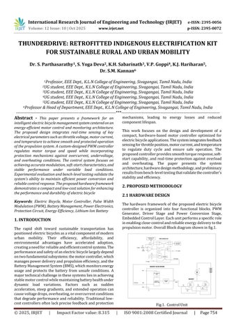
The hardware framework of the proposed electric bicycle controller is organized into four functional blocks PWM Generator, Driver Stage and Power Conversion Stage, EmbeddedControlLayer.Eachunitperformsaspecificrole inenablingclose-controlandreliableenergydeliverytothe propulsionmotor.OverallBlockdiagramshowninfig.1

Fig.1. ControlUnit

International Research Journal of Engineering and Technology (IRJET) e-ISSN: 2395-0056

Volume: 12 Issue: 10 | Oct 2025 www.irjet.net p-ISSN: 2395-0072

2.1.1 PWM Generator

The control block is responsible for generating the pulsewidth-modulated (PWM) signal that dictates motor speed andtorque.Itcomparesthethrottle-derivedreferencewith real-timefeedbackfromcurrentandtemperaturesensorsto regulatethedutycycle.Themodulationdynamicallyadjusts the switching period to achieve smooth acceleration and prevent jerks during start-up. Additionally, this block incorporatesprotectionlogicthatlimitsthemaximumduty cycle during overcurrent or overheating conditions, enhancingsystemdurabilityandridersafety,showninfig.2

The control logic operates from a regulated low-voltage supply and functions as the central processing stage, interfacingboththesensingandactuationlayers

2.1.2 Driver Stage

The driver circuit acts as a power-level shift between the low-voltagecontrolsignalsandthehigh-currentswitching devicesintheinverterbridge.Itsroleistoprovidesufficient gatedrivestrength,fastswitchingcapability,andelectrical isolation when required. This ensures that the control signalscaneffectivelymodulatethemotorcurrentwithout distortion or delay. Proper gate resistance and dead-time control in this block are essential to minimize switching lossesandavoiddevicecross-conduction,showninfig.3

2.1.3 Power Conversion Stage

Thepowerstagedeliverstherequiredenergytothemotor basedonthePWMcommandreceivedfromthedriverblock. It utilizes power semiconductor switches configured to handle the rated current and voltage of the propulsion motor.Duringoperation,theswitchesalternateconduction paths to regulate average motor voltage and speed. The stagealsoincorporatesfreewheelingandsnubberpathsto manageinductivetransients,ensuringsafeoperationunder dynamic loads. The block serves as the final actuation element, translating control decisions into mechanical torqueatthemotorshaft.

2.1.4 EMBEDDED CONTROL LAYER

Thislayerhandlesdirectmotorregulation,dataacquisition, and protection routines. Real-time parameters related to throttle command, electrical load, supply voltage, and thermal conditions are continuously monitored and processed to generate a pulse-width-modulated (PWM) controlsignal.Thealgorithmemploysclosed-loopfeedback tomaintainstabletorqueresponseandpreventovershoot duringacceleration.Faultconditionssuchasovercurrentor overheating trigger duty-cycle limitation and motor shutdownlogic.Theembeddedfirmwareoperatesonalowlatencycontrollooptoensureresponsivenessandreliability underdynamicloadconditions.

3. RESULT AND DISCUSSION

The performance evaluation of the proposed system was carried out through hardware testing of the motor controller.Theresultsconfirmthatthecontrolandfeedback layers operate coherently to support stable propulsion, efficient energy utilization, and reliable protection under dynamicoperatingconditions.

3.1 Hardware Testing and Controller Performance

Bench-levelexperimentswereperformedusingaprototype setup comprising the controller, battery pack, and permanent-magnet DC motor under variable throttle and load conditions. Oscilloscope measurements verified the stabilityofthepulse-width-modulated(PWM)signal,with linearduty-cyclevariationinresponsetothrottleinput.The motor exhibited smooth acceleration and steady torque acrosstheoperatingrange,confirmingcorrectcomparator response and effective current-limiting action. Thermal feedbacksuccessfullytriggeredduty-cyclereductionwhen the device temperature exceeded preset thresholds, demonstratingthereliabilityoftheprotectionloop.

3.2 Waveform Analysis

Thewaveformanalysisprovidesinsightintothemodulation characteristics of the controller under varying throttle inputs. The PWM output of the PWM generator was

Fig.2 PWMGenerator
Fig.3.MOSFETDriverCircuit

International Research Journal of Engineering and Technology (IRJET) e-ISSN: 2395-0056

Volume: 12 Issue: 10 | Oct 2025 www.irjet.net p-ISSN: 2395-0072

observedatthreerepresentativedutycycles10%,50%,and 90% corresponding to low, medium, and high throttle positions.

At 10% duty cycle, narrow pulses indicate minimal conductiontime,suitableforlow-speedoperation,shownin fig.4

At50%dutycycle,thepulsewidthincreasesproportionally, delivering moderate torque while maintaining efficiency, showninfig.5

At 90% duty cycle, wide pulses demonstrate nearcontinuousconduction,representingmaximummotordrive conditions,showninfig.6

Themeasuredwaveformsconfirmthelinearityandstability ofduty-cyclecontrolacrossthethrottlerange.Nodistortion or jitter was observed, indicating reliable switching and effective feedback regulation. This analysis validates the performanceofthemodulationstageandconfirmsproper functioningoftheprotectionandsensingcircuitswithinthe designedcontrolframework.

4. CONCLUSIONS

Theexperimentalresultsvalidatetheconceptualdesignof anenergy-efficientE-cyclecontrollerdevelopedforreliable propulsion and system protection. Hardware testing confirmedstablePWMgeneration,smoothtorqueresponse, and effective feedback regulation under varying load conditions. The integrated sensing and protection mechanisms successfully limited overcurrent and thermal stress, ensuring safe and efficient operation. Future work will focus on extending the controller for higher power ratings, integrating regenerative braking, and conducting long-durationfieldtrialstoassessperformanceunderrealworldconditions.

REFERENCES

[1] Yadlapalli, Ravindranath Tagore, Anuradha Kotapati, Rajani Kandipati, and Chandra Sekhar Koritala. "A review on energy efficient technologies for electric vehicle applications." Journal of Energy Storage 50 (2022):104212

[2] Parthasarathy, S., P. G. Prabu, R. Praveen Thiagarajan, and R. Arun Kumar. "Design and Implementation of Optimized Controller for E-Vehicles." Journal of Engineering Research and Reports 24, no. 12 (2023): 75-88K.Elissa,“Titleofpaperifknown,”unpublished.

[3] Bendjedia, Bachir, Saad Chouireb, and Nassim Rizoug. "FaultTolerantControlofPMSMDriveBasedonVoltage Sensor for Electric Vehicle Application." In 2023 IEEE VehiclePowerandPropulsionConference(VPPC),pp.16.IEEE,2023.

[4] T.N.Kumar,“DevelopmentofaLow-CostElectricBicycle forSustainableTransportation,” InternationalJournalof Engineering Research and Applications,2020.

[5] M. R. Patel, “Design and Simulation of a Motor Drive System for Electric Bicycle,” International Journal of Scientific & Engineering Research,2021

[6] LorenzoStilo,HeinzLugo,DianaSegura,VelandiaPaul, ConwayP,AndrewA.“Personalisedcontrollerstrategies for next generation intelligent adaptive electric bicycles.” IEEE Transactions on Intelligent TransportationSystems;2022

Fig.4.10%DutyCycle
Fig.5.50%DutyCycle
Fig.6 90%DutyCycle

International Research Journal of Engineering and Technology (IRJET) e-ISSN: 2395-0056

Volume: 12 Issue: 10 | Oct 2025 www.irjet.net p-ISSN: 2395-0072

[7] RekhaJ,ThamizhThendralTM,VijayakumarK.“Electric vehiclemotor,converter,controllerandchargingstation with challenges and configurations: Review.” International Journal of Renewable Energy Research. 2022.

[8] Yang Liu. Jigui Miao, Quan Yin, Haoran Wang. “Degradation Detection of a DC/DC Buck Converter Based on Feature Extraction.” IEEE Transactions on PowerElectronics;2025

[9] C.Wu et al.,“Designand Control ofa BrushDC Motor DriveSystemforE-bike,” IEEETransactionsonIndustrial Electronics,2016.

[10] A. Y. Javaid et al., "Smart Electric Bicycle With IoT Integration," IEEE Access,vol.7,2019.

Turn static files into dynamic content formats.

Create a flipbook
Issuu converts static files into: digital portfolios, online yearbooks, online catalogs, digital photo albums and more. Sign up and create your flipbook.