International Research Journal of Engineering and Technology (IRJET)
e-ISSN: 2395-0056
Volume: 12 Issue: 05 | May 2025
p-ISSN: 2395-0072
www.irjet.net
Simulation Based Study of Diode Clamped Multilevel Inverter Using Feedback V/f Strategy Priya S. Sontakke1, Shiwani Rasekar 2, Vishal Pimpalkar3 1P.G Student of Electrical Engineering Department, Ballarpur Institute of Technology, Ballarpur, India 2Assistant Professor of Electrical Engineering Department, Ballarpur Institute of Technology, Ballarpur, India 3Assistant Professor of Electrical Engineering Department, Ballarpur Institute of Technology, Ballarpur, India
---------------------------------------------------------------------***--------------------------------------------------------------------enhances the stability and dynamic response of the Abstract - This Project focuses on the Simulation based
system, improving its performance under different load conditions.
Study of a three phase three-level Diode Clamped Multilevel Inverter (DCMLI), displaying eight switches and combining a closed-loop Voltage-to-Frequency (V/f) feedback strategy for the performance of three-phase squirrel cage induction motors. The Space Vector Pulse Width Modulation (SVPWM) technique is used to analyze the implementation of the system through both simulation and experimental validation, utilizing MOSFETs as the switching devices. The V/f control loop make sure a stable voltage-to-frequency ratio, supporting steady motor operation over different speed ranges. Instantaneously to check data provide essential insights into the system's behavior, aiding in the development of energy-efficient and precise motor control solutions. Key performance parameters, like Total Harmonic Distortion (THD), power factor, dynamic response and efficiency are assessed across various operating conditions. The results of this research contribute to the enhanced implementation of multilevel inverters in industrial motor drive applications.
While conventional two-level inverters have been widely used in industrial motor drive systems, they have notable drawbacks, such as high harmonic distortion, electromagnetic interference, common-mode voltage issues, and increased switching stress. Multilevel inverters provide a solution by generating AC output voltages from multiple DC voltage levels, which significantly reduces these limitations. The Three-level DCMLI strikes an optimal balance between performance improvements and system complexity, making it particularly suitable for medium-power motor drive applications. This research contributes to the development of optimized motor drive systems, focusing on energy efficiency, power quality, and reliability—key concerns in industrial applications. By analyzing the performance of the Threelevel DCMLI using closed-loop V/f control and Space Vector modulation, the study offers valuable insights for engineers and system designers in industries such as manufacturing automation, HVAC, water pumping, and renewable energy systems.
Key Words: Diode Clamped Multilevel Inverter (DCMLI), V/f Closed Loop, SVPWM, Matlab Simulation
1.INTRODUCTION As industrial applications continue to evolve, the demand for motor control systems that are efficient, reliable, and precise is increasing rapidly. Among the various types of power electronic converters, multilevel inverters have become a preferred choice for medium and high-power applications due to their ability to produce high-quality output waveforms, with lower harmonic distortion and reduced switching losses. This study focuses on the Three-level Diode Clamped Multilevel Inverter (DCMLI) with eight switches, implementing closed-loop Voltage/Frequency (V/f) control for three-phase asynchronous induction motor drives.V/f control has long been a popular choice for industrial motor control due to its simplicity and reliability. By maintaining a constant voltage-to-frequency ratio, this technique ensures proper motor magnetization across various speed ranges, preventing problems such as over-fluxing at low speeds and under-fluxing at high speeds. The use of a closed-loop feedback system further
© 2025, IRJET
|
Impact Factor value: 8.315
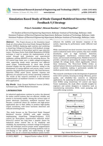
Fig 1 shows the flowchart of system
|
ISO 9001:2008 Certified Journal
|
Page 1828