
International Research Journal of Engineering and Technology (IRJET) e-ISSN: 2395-0056
Volume: 12 Issue: 07 | JUL 2025 www.irjet.net p-ISSN: 2395-0072
![]()

International Research Journal of Engineering and Technology (IRJET) e-ISSN: 2395-0056
Volume: 12 Issue: 07 | JUL 2025 www.irjet.net p-ISSN: 2395-0072
Harish Nutraganti
1
, Prof. Trupti Narkhede2 , Prof. P. J. Salunke3
1PG student, Dept. of Structural Engineering, M.G.M college of Engineering, Maharashtra, India
2 Professor, Dept. of Structural Engineering, M.G.M college of Engineering, Maharashtra, India
3 HOD, Dept. of Structural Engineering, M.G.M college of Engineering, Maharashtra, India
Abstract - This paper highlights a common construction error related to the misplacement of longitudinal reinforcementintheboundaryelementsofshearwalls.These elements are usually designed with different percentages of reinforcement (Ast) at each end. However, during execution especially at the footing level if the exact alignment or direction of the shear wall is not correctly interpreted, the reinforcementmaybeplacedincorrectly.Thisoftenoccursdue to a lack of proper supervision or the involvement of an unskilled workforce.
Ifthiserrorgoesunnoticedandthesuperstructureisbuiltover it, it can lead to serious structural effects at later stages, especially under load conditions. The variation in reinforcement between the two ends can compromise the intended behavior of the wall. This paper provides a detailed explanation of this specific error, how it typically occurs during construction, and the potential stages of failure that may result. Through comparative analysis based on differences in Ast percentage on both ends, the paper also highlightshowsucherrorsaffectthestructuralperformance. The study aims to increase awareness and encourage improved construction practices and site monitoring to prevent such critical mistakes.
Key Words: Constructionerror,Shearwall,Ast,failure.
Inreinforcedconcretebuildings,especiallythoselocatedin seismicregions,shearwallsareessentialforresistinglateral forces and maintaining overall stability. These walls are typicallyprovidedwithboundary elementsattheiredges, where longitudinal reinforcement is designed in varying percentagestohandletensionandcompressiondemands.

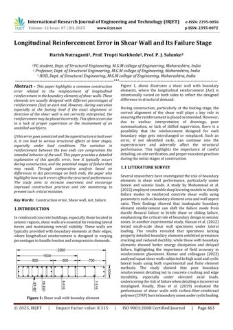
Figure 1, above illustrates a shear wall with boundary elements, where the longitudinal reinforcement (Ast) is intentionally varied on both sides to reflect the designed differenceinstructuraldemand.
During construction, particularly at the footing stage, the correct alignment of the shear wall plays a key role in ensuringthereinforcementisplacedasintended.However, due to unclear interpretation of drawings, poor communication, or lack of skilled supervision, there is a possibility that the reinforcement designed for each boundary edge gets interchanged or misplaced. Such an error, if not identified early, can continue into the superstructure and adversely affect the structural performance. This highlights the importance of careful detailing,on-siteverification,andproperexecutionpractices duringtheinitialstagesofconstruction.
Severalresearchershaveinvestigatedtheroleofboundary elements in shear wall performance, particularly under lateral and seismic loads. A study by Mohammad et al. (2022)employedensembledeeplearningmodelstoclassify failure modes in reinforced concrete shear walls using parameterssuchasboundaryelementareaandwallaspect ratio. Their findings showed that inadequate boundary element reinforcement can shift the failure mode from ductile flexural failure to brittle shear or sliding failure, emphasizingthecriticalroleofboundarydesigninseismic zones.Inanotherexperimentalstudy,Hassanetal.(2022) tested small-scale shear wall specimens under lateral loading. The results revealed that specimens lacking properlydetailedboundaryelementsexhibitedpremature crackingandreducedductility,whilethosewithboundary elements showed better energy dissipation and delayed failure, highlighting the importance of field accuracy in reinforcement placement. Kumar and colleagues (2023) analyzedsquatshearwallssubjectedtohighaxialandcyclic lateral loads using both experimental and finite element methods. The study showed that poor boundary reinforcementdetailingled toconcretecrushingandedge instability, especially under elevated axial loads, underscoringtheriskoffailurewhendetailingisincorrector misaligned. Finally, Zhao et al. (2019) evaluated the performance of shear walls with carbon-fiber-reinforced polymer(CFRP)barsinboundaryzonesundercyclicloading.

International Research Journal of Engineering and Technology (IRJET) e-ISSN: 2395-0056
Volume: 12 Issue: 07 | JUL 2025 www.irjet.net p-ISSN: 2395-0072
Their research demonstrated that proper boundary reinforcementnotonlyimproveslateralresistancebutalso preventsearlyfailure,makingitsuitableforretrofittingand error correction in field conditions. Collectively, these studies underline that even small errors in boundary element detailing significantly impact the safety and performanceofshearwalls.
Toevaluatetheimpactofboundaryelementreinforcement errors, a G+13 reinforced concrete building was modeled using ETABS software. The structure was analyzed under seismicloadingconditions,consideringaresponsereduction factor(R)of5asperIS1893provisionsforductiledetailing, andlocatedinSeismicZoneIV.

Insteadofapplyinguniformreinforcementacrossallshear walls,thedesignwascarriedoutusingtheSimplifiedCenter andTorsion(C&T)methodavailableinETABS.Thismethod automatically assigns varying longitudinal reinforcement (Ast)valuestoeachboundaryelementbasedonthewall's position,loadingdemand,andmomentprofile.Asa result, eachshearwallinthebuildingreceiveddifferentAstvalues on its two ends, reflecting a realistic design approach. A summarytablelistingtheAstvaluesforeachshearwalland theircorrespondingboundaryzonesisattachedbelow.
Table -1: ShearwalldesignwithC&Tmethod

Theinitialdesign,asshowninTable1,provides aprecise distribution of longitudinal reinforcement (Ast) in each shearwall,withvaryingvaluesassignedtothetwoboundary elements based on their respective force demands. This ensures structural efficiency and compliance with code requirements.However,insituationswhereaconstruction error leads to the reversal or misplacement of these reinforcements at the boundary zones, the shear wall developsanon-uniformreinforcementcondition creating one under-reinforced edge and one over-reinforced edge. Thisdiscrepancydisruptstheintendedmomentresistance capacity of the wall and can result in premature failure underlateralorseismicforces.Thewallismostvulnerable on the side originally designed to resist higher tension forces,wheretheAstbecomesinsufficientduetotheerror. ThetablebelowsummarizesthepercentagedifferenceinAst betweenthetwoboundaryelementsforeachshearwalland identifiesthecorresponding failurestagelikelytooccurif suchamisplacementhappensduringconstruction.
Table 2:%DifferenceinEdgeAstvs.FailureStage

From the data presented in the table, a clear interpretation can be made regarding the relationship betweenthepercentagedifferenceinAstattheshearwall edgesandthecorrespondingfailurestageasoutlinedbelow,
If Ast difference < 25%, failure in the Shear wall wouldoccurat1.5factoredloadcase.
If Ast difference > 25%, failure in the Shear wall would occur at 1.2 factored load case or in some cases,failure wouldoccur asearlyas1.0 factored load.
If Ast difference > 50%, failure in the Shear wall wouldoccurat1.0factoredloadcaseand1.0factor meansitwillfailduringtheconstructionstage.
Inconclusion,reinforcementinstructuralelementsplaysa vital role in ensuring the overall stability and safety of a

International Research Journal of Engineering and Technology (IRJET) e-ISSN: 2395-0056
Volume: 12 Issue: 07 | JUL 2025 www.irjet.net p-ISSN: 2395-0072
structure.Whileaccuratedesignisessential,italoneisnot sufficient the correct execution of reinforcement detailing on-siteisequally,ifnotmore,important.Specifically,inthe case of longitudinal reinforcement errors in shear wall boundaryelements,wherereinforcementwithdifferentAst values is mistakenly interchanged, the wall becomes structurallycompromised.Suchanerrorcancausethewall tofailatacriticalstageofloading.Thefindingsindicatethat when the percentage difference in Ast between the two boundaryelementsislessthan25%,failureoccursundera 1.5factoredload.Fordifferencesexceeding25%,failureis expectedundera1.2factoredload,andwhenthedifference crosses50%,thewallmayfailevenundera1.0factoredload potentiallyduringtheconstructionstageitself.Theseresults highlighttheurgentneedforstricton-sitequalitycontrol, skilledsupervision,andaccurateinterpretationofstructural drawings.Ensuringproperexecutionofreinforcementnot only enhances the strength and ductility of structural elementsbutalsopreservestheserviceabilityandlong-term durabilityoftheentirebuilding.
[1] Mohammad,I.,Abdulrazeg,A.,Aghayan,I.,&Elbeltagi, E.(2022).Failuremodedetectionofreinforcedconcrete shear walls using ensemble deep neural networks. International Journal of Civil Engineering and Mechanical Research, 13(1), Article 17.M. Young, The TechnicalWriter’sHandbook.MillValley,CA:University Science,1989.
[2] Hassan, S. M., Sayed, M. A., & Mohamed, A. M. (2022). Experimental investigation of small-scale shear walls underlateralloads.JournalofEngineeringandApplied Science,69,Article141
[3] Kumar,A.,Pandey,M.,&Rana,A.(2023).Experimental and finite element study of squat shear walls under combinedcyclicandhighaxialloads. Buildings,13(8), 2104.
[4] Zhao, Y., Kim, S. J., & Park, H. G. (2019). Experimental studyonseismicresistanceofRCshearwallswithCFRP bars in boundary elements. International Journal of ConcreteStructuresandMaterials,13(1),1–12.
[5] IS456:2000 – PlainandReinforcedConcrete–Codeof Practice(FourthRevision)
[6] IS 1893 (Part 1):2016 – Criteria for Earthquake ResistantDesignofStructures–GeneralProvisionsand Buildings
[7] IS 13920:2016 – Ductile Detailing of Reinforced ConcreteStructuresSubjectedtoSeismicForces–Code ofPractice
[8] IS875(Part1):1987 – CodeofPracticeforDesignLoads (OtherthanEarthquake)forBuildingsandStructures–DeadLoads
[9] IS875(Part2):1987 – CodeofPracticeforDesignLoads (OtherthanEarthquake)forBuildingsandStructures–ImposedLoads
[10] IS1893:2002 – CriteriaforEarthquakeResistantDesign ofStructures