International Research Journal of Engineering and Technology (IRJET)
e-ISSN: 2395 -0056
Volume: 04 Issue: 07 | July-2017
p-ISSN: 2395-0072
www.irjet.net
Novel High Voltage Buck Boost Converter Prashant Kumar Srivastava1, Prof. Madhu Upadhyay2 Power Electronics(NRI,Bhopal) Madhu Upadhyay(H.O.D(Electrica&Electronics Engg.NRI,Bhopal)) ---------------------------------------------------------------------***--------------------------------------------------------------------2Prof.
1M.Tech
Abstract – This paper presents a new high efficiency buck
boost dc-dc- converter with low voltage renewable energy resources. The proposed converter utilizes a low voltage DC supply and boost it to required dc voltage. In this paper Pi controller is used with snubber circuit. The result are that there is very les power loss and the efficiency of the system is high. In comparison with the conventional buck boost converter.
1. INTRODUCTION In modern world the cost of producing energy with nonrenewable energy source is increasing day by day and there is constant threat of limited amount of availability of it, so we have to switch to different energy sources like renewable energy sources. A dc-dc converter with is very essential now as it can be used to convert low voltage to required high voltage and we can say that conversion of a regulated dc voltage from unregulated dc voltage. An unregulated dc source may be from output of rectified solar cell or battery etc. the sources can be varied but the main objective is to get the input and convert it into required output with better efficiency and minimal loss of energy. There are many ways to convert dc-dc but buck boost dc-dc converter has a better current driving capability and has good efficiency. Although many different design have been proposed to improve the efficiency of the converter an to achieve high voltage gain such as using switched capacitor and a coupled inductor. The basic circuit of buck-boost converter is shown in fig.1. The output of converter is controlled by closed loop and alternating its MOSFET(switch) gate signal. PI controller is used as it is more widely used for industrial application. Conventional high voltage converter without transformer cannot provide such a high voltage. In high voltage dc-dc converter coupled inductor is used to improve the voltage gain , snubber circuit to absorb stray inductance.
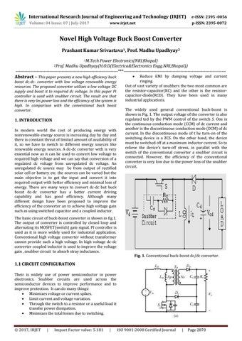
Reduce EMI by damping voltage and current ringing. Out of vast variety of snubbers the two most common are the resistor-capacitor(RC) and the other is the resistorcapacitor-diode(RCD). They have been used in many industrial applications. The widely used general conventional buck-boost is shown in Fig. 1. The output voltage of the converter is also regulated ted by the PWM control of the switch S. One is the continuous conduction mode (CCM) of dc current and another is the discontinuous conduction mode (DCM) of dc current. In the discontinuous mode of t he turn-on of the switching device is a ZCS. On the other hand, the device must be switched off at a maximum inductor current. So to relieve the device’s turn-off stress, in parallel with the switch of the conventional converter a snubber circuit is connected. However, the efficiency of the conventional converter is very low due to the power loss of the snubber circuit.
Fig. 1. Conventional buck-boost dc/dc converter.
1.1 CIRCUIT CONFIGURATION Their is widely use of power semiconductor in power electronics. Snubber circuits are used across the semiconductor devices to improve performance and to improve protection. It can do many things: Minimizes voltage or current spikes. Limit current and voltage variation. Through the switch to a resistor or a useful load it transfer power dissipation. Minimizes the total losses due to switching.
© 2017, IRJET
|
Impact Factor value: 5.181
|
ISO 9001:2008 Certified Journal
|
Page 2870