International Research Journal of Engineering and Technology (IRJET)
e-ISSN: 2395-0056
Volume: 04 Issue: 07 | July -2017
p-ISSN: 2395-0072
www.irjet.net
OPTIMIZATION OF JET ENGINE G.Vinoth. Student, Department of Aeronautical Engineering, V.S.B. Engineering College, Karur, Tamilnadu, India. -----------------------------------------------------------------------***-----------------------------------------------------------------------
Abstract: The conventional jet engine is optimized to
the compressors using separate airstream, the mass flow rate will be more which results in high thrust.
produce high thrust and low specific fuel consumption. The changes are made in compressor which is responsible for the pressure raise in the total process. The compressor section is replaced with two smaller compressors which are parallel to each other with separate individual inlets. It is designed that the two compressors do compression separately and produce high pressure raise. This pressure raise will reduce the fuel demand considerably and increase in thrust.
Key Words: High Thrust Jet Engine, Low Fuel Consuming Jet Engine, Double Compressor Jet Engine. 1. INTRODUCTION Jet Engine is a machine which converts chemical (Fuel) energy into Thrust. Jet engines are the power source for most of the aircrafts flying now. Generally it has five sections like Inlet, Compression Section, Combustion section, Turbine and Nozzle. Every section depends on each other. Change in the performance of any above section will create a huge change in the performance of the jet engine. The resources of Air Turbine Fuel are becoming very low in the Earth. Nearly 70% of the total expense of one flight is for the fuel. Lot of innovations is emerging to reduce fuel consumption in aircrafts. This is one among them which considerably reduces the fuel consumption.
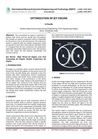
Figure-1: Front View of the Engine.
3. DESIGN As the new design engine has two compressors, the size of the engine will be very high and it produces serious problems in aircraft performance. So the size of each compressor is reducing to žth of the normal compressor. It will be in the scale ratio of 1.5(2 compressors):1 with normal engine compressor. Thus the frontal size of jet engine is 50% more than the normal engine. The number of stages in compressor depends on the application. The engine is roughly designed with 10 stages in compressor. The design of two inlets is made identical to each other in order to have uniform compressor performance. The engine has two ducts as shown the figure.1 for the secondary flow like in turbofan engine. This will help for engine cooling purpose.
2. CONCEPT Generally jet engine has an axial compressor which is driven by turbine shaft to achieve required pressure raise. Now it is replaced with two smaller compressors which will do the same compression individually. Both the compressors are provided with the separate inlets through which separate air stream will flow into the respective compressors as shown the figure.1.
The turbine shaft is connected with two compressors through gear wheels as shown the figure.2. The separate lubricant system is provided to gear wheels in order to reduce the gear loss. Various types of combustion chamber are available in aviation industry but I prefer annular combustion chamber for this engine. Annular combustor can take pressurized air from two compressors easily and produce high performance. The rest section of engine will be same as the normal engine.
As the compression takes place in two compressors, the total pressure raise of air stream at the entry of combustor should be higher than the single conventional compressor. Thus the fuel required to attain a specific pressure raise at the turbine inlet will be lowered. It reduces the specific fuel consumption of the engine. As
Š 2017, IRJET
|
Impact Factor value: 5.181
|
ISO 9001:2008 Certified Journal
| Page 672