International Research Journal of Engineering and Technology(IRJET) Volume: 04 Issue: 05 | May -2017
www.irjet.net
e-ISSN: 2395 -0056 p-ISSN: 2395-0072
Comparative Study of Voltage source inverter with Z source inverter Devadkar Supriya1, Gaikwad Snehal2, ZagadeNutan3 ,Pawar P.B.4 123Student
of S.B.Patil College of Engineering,Indapur Professor, Dept. of Electrical Engineering, S.B.Patil college of Engineering,Indapur,Maharastra,India ---------------------------------------------------------------------***--------------------------------------------------------------------(SCR), Metal Oxide Semiconductor Field Effect Transistor Abstract -An implementation of the constant V/Hz 4Assistant
(MOSFET), or a combination of such devices with the series diode is used. These devices act as switching devices according to their switching sequence the three phases AC output was obtain is given to load. For CSI shape of the output voltage is depending on load and output current is independent of load. The CSI is to work as a current source by means of the large series inductor at its output and a current regulation loop.
control strategy for proposed impedence source inverter(Z – source inverter)fed induction motorin closed loop control has emerged as a powerful tool for controlling induction motor drives to achieve high performance and good dynamic response. In this paper, a new control scheme is developed for control of the induction motor drive by ZSI by boosting line voltage, lowering harmonics distortion,maintaining speed of the drive. In this scheme stator voltage is boosted for obtaining desired torque response and maintain constant frequency and speed below rated speed. Simulation results of the proposed Z –source inverter scheme and traditional inverter are presented which compared for their comparative study.
1.1.1 LIMITATIONS OF CSI: 1. The ac output voltage has to be greater than the original dc voltage that feeds the dc inductor or the dc voltage produced is always smaller than the ac input voltage. There-fore, the current-source inverter is a boost inverter for dc-to-ac power conversion and the current source converter is a buck rectifier (or buck converter) for ac-todc power conversion. For applications where a wide voltage range is desirable, an additional dc–dc buck (or boost) converter is needed. The additional power conversion stage increases system cost and lowers efficiency.
Key Words: Z source inverter ,Induction motor drive, Harmonics distortion
1.INTRODUCTION Nowadays, energy storage and conversion plays the vital role in the field of distributed generation.Many of them uses converter such as rectifier and inverter. This paper reviews some of traditional inverter topology such as current source inverter and voltage source inverter with their drawbacks hence introducing newer topology as zsource inverter which had discuss further.
2. At least one of the upper devices and one of the lower devices have to be gated on and maintained on at time. Otherwise, an open circuit of the dc inductor would occur and destroy the devices. The open-circuit problem by EMI noise mis-gating-off is a major concern of the inverter’s reliability. Overlap time for safe current commutation has to be required in the current source inverter, which may causes waveform distortion, etc.
1.1 CURRENT SOURCE INVERTER
3. The main switches of the current source inverter have to block reverse voltage that requires a series diode to be used in combination with high-speed and highperformance transistors such as insulated gate bipolar transistors (IGBTs).
1.2 . VOLTAGE SOURCE INVERTER:
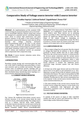
Fig 1: Current Source Inverter
It consists of DC source as input or fully controlled rectifier fed with AC source and followed by a filter or diode bridge rectifier followed by chopper.
Fig. 1.shows the traditional three-phase current source inverter structure. A dc current source feeds the main converter circuit, a three-phase bridge. The voltage source such as a battery, fuel-cell stack, diode rectifier, or thyristor inverter provides dc current source fed by the dc inductor. The power transistor such as Insulated Gate Bipolar Transistor (IGBT), Silicon ControlledRectifier © 2017, IRJET
|
Impact Factor value: 5.181
|
ISO 9001:2008 Certified Journal
|
Page 360