International Research Journal of Engineering and Technology (IRJET)
e-ISSN: 2395 -0056
Volume: 04 Issue: 04 | Apr -2017
p-ISSN: 2395-0072
www.irjet.net
FEA and Experimental Analysis of Composite I-Beam Subjected to Tensile Test. Mr. Londhe A.H.1, Professor,Mechanical Engineering Department, Fabtech Engineering College Sangola, Maharashtra, ---------------------------------------------------------------------***--------------------------------------------------------------------2. FEA OF 1ST I-BEAM SPECIMEN WITH ARALDITE Abstract - This paper presents experimental analysis of 2015 ADHESIVE adhesively bonded GFRP I-Beam in pulling load which 1
changes damage occurs, due to alterations in Adhesives used. The use of adhesive bonding in advanced composite structures has potential to reduce weight as compared to mechanical fasteners. Tensile tests were carried out for four composite I-beam specimens with two adhesives. The adhesives used have different properties. Web and flanges of I-Beam specimen is made of material GFRP and for joining web to flanges two different adhesives are used for two separate specimen. The present work is focused on quantifying and enhancing the failure load of GFRP composite I-Beam.
Table -2: Properties of Araldite 2015
Key Words: Web, Flanges, GFRP, I-Beam, Failure Load, Composite
1.INTRODUCTION An I-beam, also known as H-beam-beam, Universal Beam, or double-T beam with an I- or H-shaped cross-section. The horizontal elements of the I beam are known as flanges, while the vertical element is termed the web. I-beams are usually made of structural steel and are used in construction and civil engineering. I-beams are widely used in the construction industry and are available in a variety of standard sizes. I-beams may be used both as beams and as columns.
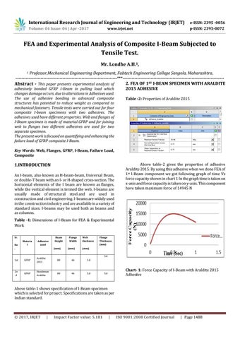
Above table-2 gives the properties of adhesive Araldite 2015. By using this adhesive when we done FEA of 1st I-Beam component we got following graph of time Vs force capacity shown in chart 1 In the graph time is taken on x-axis and force capacity is taken on y-axis. This component have taken maximum force of 14945 N
Table -1: Dimensions of I-Beam for FEA & Experimental Work Sr. No .
Materia l
Adhesive used
Beam Height
Flange Width
(mm)
(mm)
Web thickness
Flange Thickness (mm)
(mm) 5.0
1st
GFRP
Araldite 2015
80
46
5.0
2n d
GFRP
Hundsman Araldite
80
46
5.0
Chart- 1: Force Capacity of I-Beam with Araldite 2015 Adhesive
5.0
Above table-1 shows specification of I-Beam specimen which is selected for project. Specifications are taken as per Indian standard.
Š 2017, IRJET
|
Impact Factor value: 5.181
|
ISO 9001:2008 Certified Journal
| Page 1488