International Research Journal of Engineering and Technology (IRJET)
e-ISSN: 2395 -0056
Volume: 04 Issue: 04 | Apr -2017
p-ISSN: 2395-0072
www.irjet.net
A Parallel Input Series Output DC/DC Converter with High Voltage Gain Ajmal M M1, Benny Cherian2, Babu Thomas3 1PG
Scholar, Dept. of EEE, Mar Athanasius College of Engineering, Kothamangalam, Kerala, India, Dept. of EEE, Mar Athanasius College of Engineering, Kothamangalam, Kerala, India 3Assistant Professor, Dept. of EEE, Mar Athanasius College of Engineering, Kothamangalam, Kerala, India ---------------------------------------------------------------------***--------------------------------------------------------------------2Professor,
Abstract - The importance of high voltage gain dc/dc
converter is increasing day by day. Conventional boost converter is unable to provide high gain without extreme duty ratio. An input parallel output series boost converter can provide a high step up gain. The converter uses two switches, two coupled inductors and a voltage multiplier module. The primary windings of coupled inductors are placed across the supply. Their connection reduces the input current ripple as it is shared by windings. The converter has high voltage gain and low voltage stress across power switches. The switches are turned on at zero current due to the leakage inductance of coupled inductor .The simulation of the converter is done in MATLAB/SIMULINK and results are obtained. Key Words: High step up gain, DC/DC converter, Low voltage stress, Coupled inductors.
1. INTRODUCTION High gain dc/dc converters are widely used in many industrial applications such as solar, fuel cell, x-rays, laser and high intensity discharge lamp ballasts for automobile headlamps[2]-[4]. Theoretically, a basic boost converter is capable of providing high conversion ratio, but extremely high duty ratio is required. In practice, extreme duty ratios are not permitted because of the large conduction losses and frequent damage of power switches. Usually it is preferable to use low voltage rated power switches having low on state resistance to reduce the conduction losses, which may not be possible in a conventional boost converter. Cascaded boost converters can provide high voltage gain[5]-[6]. But high voltage stress across the switches and poor efficiency are the disadvantages. DC/DC converters using coupled inductors is a good alternative to obtain a high step up gain[7], provided the leakage inductances are handled properly. Interleaved control is found very useful in reducing the input current ripple of the converter[8]-[10]. Two different boost converter structures can be combined to produce twice the voltage gain by connecting there inputs in parallel and output in series. The two independent inductors of this combined converter is replaced by two coupled inductors. Connecting the primary windings of coupled inductors in parallel and secondary windings in series a high step up DC/DC converter is derived. An input parallel output series boost converter with dual coupled inductors can be Š 2017, IRJET
|
Impact Factor value: 5.181
|
used for high step up and high power applications. The interleaved control adopted reduces the input current ripple considerably. This configuration inherits the merits of high voltage gain, low voltage stress across the power switches and low output voltage ripple. Also, the converter is capable to turn on the active switches at zero current and hence reduce switching losses.
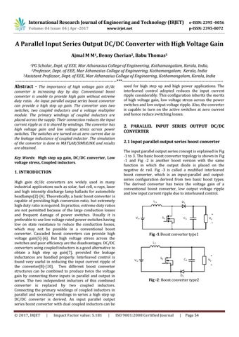
2. PARALLEL INPUT SERIES OUTPUT DC/DC CONVERTER 2.1 Input parallel output series boost converter The input parallel output series concept is explained in Fig -1 to 3. The basic boost converter topology is shown in Fig -1 and Fig -2 is another boost version with the same function in which the output diode is placed on the negative dc rail. Fig -3 is called a modified interleaved boost converter, which is an input-parallel and outputseries configuration derived from two basic boost types. The derived converter has twice the voltage gain of a conventional boost converter, low output voltage ripple and low input current ripple due to interleaved control.
Fig -1:Boost converter type1
Fig -2: Boost converter type2
ISO 9001:2008 Certified Journal
|
Page 54