International Research Journal of Engineering and Technology (IRJET)
e-ISSN: 2395 -0056
Volume: 04 Issue: 04 | Apr -2017
p-ISSN: 2395-0072
www.irjet.net
Generation of Extremely Low Frequency below 1Hz Rupali S Bisen PG Student, Department of Electrical Engineering, G. H. Raisoni college of Engineering, Maharashtra, India ---------------------------------------------------------------------***--------------------------------------------------------------------2. Related Work The work carried out by me is subdivided into research since 1935. Due to long wavelength, ELF waves are used for long distance communication through solid medium two parts :-
Abstract - Generation of low frequency has been a topic of
unaffected by hindrances. Extremely Low Frequency (ELF) waves are basically used for communication through a solid medium. They can penetrate easily into the earth, through rock, and under sea water for communication with submarines. Ultra-capacitors, since its invention has achieved a significant progress due to its charge holding capability over the conventional capacitors. This makes its use possible for low current, low voltage, low power applications. However, it posses several challenges for producing Extremely Low Frequency (ELF). Simulations will be carried out in MATLAB/simulink environment thus generating frequency of about 0.5 Hz.
A] ELF Generation using LC Tank Oscillator There are several variations in oscillators namely, sine wave oscillators, RC or CR oscillators, crystal oscillators, relaxation oscillators, sweep oscillator and LC oscillators. There has been a consistent development in oscillation technologies ever since the LC oscillator has been built by Elihu Thomson in 1892. The LC oscillators use inductor and capacitor to determine the frequency at which it oscillates. The stored energy in the inductor is released to charge the capacitor which in turn discharges and stores energy in the magnetic field of the inductor. The process is cumulative and hence it is regarded as tank circuit. The LC oscillator offers approximately sinusoidal waveform and has greater frequency stability over the other oscillators.
Key Words: Extremely Low Frequency, low power, sub soil seismic communication, half bridge inverter
1.INTRODUCTION Low frequency devices are used for seismic data measurements of rock and reservoir parameters. It is important to have a set bandwidth of low frequency which otherwise could result in inaccurate development decisions and drilling. The extremely low frequency of the order of 02Hz is obtained from seismic velocity data. Thus low frequency modeling has become crucial [1]. ELF waves find its extended applications for infrastructure monitoring, sport ground, navigation, border patrolling, and agriculture. Oscillator is best suited for such applications which produce periodic oscillating signal such as sine wave, triangular wave or square wave. The wave shape and amplitude are determined by the design of oscillator circuits. The output frequency may be kept fixed or variable depending upon the requirement. Communication system can operate on a frequency which is below 100Hz, as they are designed with unique properties. Because of these properties, the US Navy has dedicated its work for the last 10 years, so as to analyze all the parameters in this frequency range and get a better understanding on the design of the communication systems, which will be used on transmitters of submarines . This work has been pursued under the name of Project Sanguine and that too world wide.[2]. Low Frequency generated up till date is of the order of 8.94 Hz using RC phase shift Ring Oscillator designed by CMOS Thyristor technique. This method also had static power dissipation of 5.7 µW.[3]
© 2017, IRJET
|
Impact Factor value: 5.181
D1
+12v dc
C Q1
C1
AC
A
B
L1
230V AC
D2
C2
L2 R
Q2
0v Half Bridge inverter
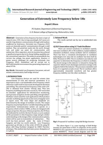
Fig-1: Proposed LF oscillator using Half Bridge Inverter The above figure 1 is a new topology of Half Bridge inverter for generation of ELF. It comprises of two power MOSFET’S, two capacitors, and two inductors in series with power MOSFET’S. Power circuit diagram used for the
|
ISO 9001:2008 Certified Journal
|
Page 599