International Research Journal of Engineering and Technology (IRJET) Volume: 04 Issue: 03 | Mar -2017
www.irjet.net
e-ISSN: 2395 -0056 p-ISSN: 2395-0072
ANALYSIS AND GAIN ENHANCEMENT OF DIFFERENT SHAPES OF SHAPES OF MICROSTRIP PATCH ANTENNA Dr.S.Sathiya Priya, M.E,Ph.D1, A.Supriya2, B.Meena Shivani3 1Professor,
ECE Department, Panimalar Institute of Technology, Tamil Nadu, India. Year UG Student, ECE Department, Panimalar Institute of Technology, Tamil Nadu, India. 3Final Year UG Student, ECE Department, Panimalar Institute of Technology, Tamil Nadu, India. -- -- -- -- -- -- -- -- -- -- -- -- -- -- -- -- -- -- -- -- -- -- -- --***- -- -- -- -- -- -- -- -- -- -- -- -- -- -- -- -- -- -- --- -- -- -- -- -2Final
A Microstrip or Patch antenna is a low-profile antenna that has various advantages over other antennas –it is a light weight, inexpensive and easy to integrate with accompanying electronics [9]. Since Microstrip antenna are often integrated with other Microstrip circuitry, a compromise must be reached between good antenna performance and circuit design. The radiating element are photo etched along with the feed lines on the dielectric substrate. The radiating patch may be square, rectangle, dipole, circular, elliptical, triangle or any other configuration [4]. While the antenna can be 3D in structure (eg. wrapped around a cylinder), it is flat and that is why patch antennas are sometimes referred to as Planar antennas.
ABSTRACT - Microstrip patch antenna with microstrip feeding gives the better gain. In this paper, the gain obtained for eight different shapes(square patch, circular patch, circular loop, square loop, cross dipole, square aperture, jeruslem cross, gridded square frequency selective surface) of microstrip patch antenna is analyzed carefully with microstrip feeding. Then designing is done using Advanced Design System(ADS) software by including Electromagnetic Band Gap(EBG) to microstrip feeding. The result was that the obtained gain is higher for microstrip patch antenna with microstrip feeding and EBG when compared to using microstrip feeding alone. Keywords: Microstrip patch antenna, Electromagnetic band gap, Gain, return loss, ADS software, resonant frequency.
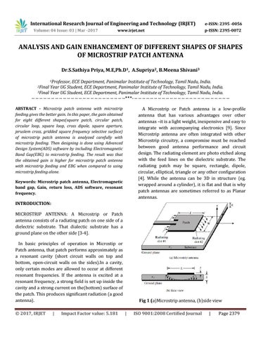
INTRODUCTION: MICROSTRIP ANTENNA: A Microstrip or Patch antenna consists of a radiating patch on one side of a dielectric substrate. That dialectic substrate has a ground plane on the other side [3-4]. In basic principles of operation in Microstip or Patch antenna, that patch performs approximately as a resonant cavity (short circuit walls on top and bottom, open-circuit walls on the sides).In a cavity, only certain modes are allowed to occur at different resonant frequencies. If the antenna is excited at a resonant frequency, a strong field is set up inside the cavity and a strong current on the(bottom) surface of the patch. This produces significant radiation (a good antenna). Š 2017, IRJET
|
Impact Factor value: 5.181
Fig 1 (a)Microstrip antenna, (b)side view |
ISO 9001:2008 Certified Journal
|
Page 2379