International Research Journal of Engineering and Technology (IRJET)
e-ISSN: 2395 -0056
Volume: 04 Issue: 03 | Mar -2017
p-ISSN: 2395-0072
www.irjet.net
AC to AC STEP DOWN CYCLOCONVERTER Viren Patel1, Dipak Makawana2, Vishal Rangpara3, Jaydipsinh Zala4 1.2.3 B.E.
4 Assistant
in Electrical Engineering, DSTC, Junagadh, Gujarat, India Professor, Department of Electrical Engineering, DSTC, Junagadh, Gujarat, India
---------------------------------------------------------------------***---------------------------------------------------------------------
Abstract - To control the speed of a single phase induction
motor in three steps using SCR based single phase cycloconverter technique. A.C. motors have great advantages of being relatively inexpensive and very reliable. The induction motors in particular are very robust. Therefore they are used in many domestic appliances such as washing machines, vacuum cleaners, water pumps, and in industries as well. Induction motor is known as constant speed machine. The difficulty of varying its speed by a cost effective device is one of its main disadvantage. As AC supply frequency cannot be changed, so this uses a thyristor controlled cycloconverter which enables control of speed in steps for an induction motor. The microcontroller used in this is arduino. A pair of slide switches are provided to select desired speed range F, F/2 and F/3 of operation of induction motor. These switches are interfaced to the microcontroller. The status of switches enables the microcontroller to deliver pulses that trigger a set of SCRs in dual bridge. Thus, the speed control of induction motor can be achieved in three steps i.e. (F, F/2 and F/3).
In step down cycloconverter forced commutation and results in an output with a frequency lower than that of the input Fo (Output Frequency) < Fs (Supply Frequency). The step down cycloconverter is physically commutated and the output frequency is limited to a value that is a fraction.
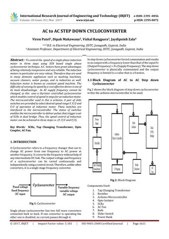
1.1 Block Diagram of AC to AC Step down Cycloconverter Fig 2 shows the block diagram of step down cycloconverter in this the arduino microcontroller to be used.
Key Words: SCRs, Tap Changing Transformer, Opto Coupler, AC Fan.
1. INTRODUCTION A Cycloconverter refers to a frequency changer that can to change AC power from one frequency to AC power at another frequency. It converts the frequency without help of any intermediate DC link. The output voltage and frequency of a cycloconverter can be varied continuously and independently using a control circuit. Therefore, unlike other converters, it is a single stage frequency converter.
Fig 2: Block Diagram Components Used:
Fig 1: Cycloconverter Single phase cycloconverter has two full wave converters connected back to back. If one converter is operating the other one is disabled, no current passes through it. Š 2017, IRJET
|
Impact Factor value: 5.181
|
1. 2. 3. 4. 5. 6. 7. 8. 9.
Tap Changing Transformer Rectifier Arduino Microcontroller Opto Isolator SCRs AC Fan Bulb Slider Switch Power Bank
ISO 9001:2008 Certified Journal
|
Page 1611