International Research Journal of Engineering and Technology (IRJET)
e-ISSN: 2395 -0056
Volume: 04 Issue: 03 | March -2017
p-ISSN: 2395-0072
www.irjet.net
Novel Ultra-Wide Band Microstrip Patch Antenna design for space research and radio astronomy applications Prince1, Payal Kalra2, Ekambir Sidhu3 1Student,
Department of Electronics and Communication Engineering, Punjabi University Patiala, India 2Student, Department of Computer Engineering, Punjabi University Patiala, India 3Assistant Professor, Department of Electronics and Communication Engineering, Punjabi University Patiala, India ---------------------------------------------------------------------***---------------------------------------------------------------------
Abstract - This paper presents the design and performance
available with different values of dielectric constant but in the proposed antenna design, FR4 (Flame Retardant) material with dielectric constant (Îľr) of 4.4 has been used.[4] An antenna can be fed by various feeding techniques, for example, co-axial feed line, proximity coupled micro strip feed, micro strip feed line.[5] The technique of feeding can be defined as the means to transfer the power from the feed line to the patch, which itself act as a radiator.[5] The International Telecommunication Union Radio communication Sector (ITU-R) has defined UWB (ultra-wide band) as an antenna transmission for which emitted signal bandwidth exceeds the 20% value of fractional bandwidth.[6] Apart from above mentioned applications, the low profile antennas have some limitations, for example, narrow bandwidth, low gain, low power handling capacity, etc.[7] The bandwidth of microstrip patch antenna can be improved by using reduced ground plane.[8][9]
analysis of an ultra-wide band (UWB) microstrip patch antenna for space research and radio astronomy applications. The proposed antenna design employs Flame Retardant (FR-4) material as substrate having a dielectric constant of 4.4 and thickness of 1.3mm. The copper material is used for patch and ground due to its low resistivity and high mechanical strength having thickness of 0.05mm. The reduction in dimensions of ground has been done to enhance the following antenna parameters impedance bandwidth, gain and directivity. The proposed antenna design has an impedance bandwidth of 5.606 GHz (10.846 GHz to 16.452 GHz) having corresponding resonant frequency at 11.82 GHz. The value of minimal return loss at corresponding resonant frequency is -31.181 dB. The calculated fractional bandwidth of the proposed antenna design is 47.42%. The performance of proposed antenna design has been analyzed in terms of impedance bandwidth (GHz), return loss (dB), gain (dB), directivity (dBi), VSWR (voltage standing wave ratio), HPBW (half power beam width) and impedance (ohms). It has been observed that the proposed gigahertz rectangular antenna design has a value of directivity and gain as 4.605 dBi and 3.973 dB, respectively at the corresponding resonant frequency. The proposed antenna has been simulated and designed using CST microwave Studio 2016. The proposed antenna can be suitably used for fixedsatellite, broadcasting satellite, space research, radiolocation and radio astronomy applications.
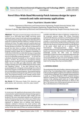
2. ANTENNA DESIGN The positioning of the patch, feedline, substrate and ground is shown in Fig. 1 corresponding to their respective thickness. In the proposed Gigahertz antenna, the substrate of thickness 1.4mm has been employed. The rectangular shaped substrate is made up of Flame Retardant (FR-4) material having a dielectric constant of 4.4. The topmost layer of the designed antenna is the radiating patch made up of copper with a thickness of 0.05 mm having dimensions as shown in the Fig. 2. The bottom view of the proposed antenna is shown in Fig. 3 with dimensions of reduced ground.
Key Words: CST Microwave Studio 2016, directivity, gain, patch antenna, radio astronomy, return loss, space research.
1. INTRODUCTION In recent years, the significant advancement in the wireless communication system demands antennas having superior performance, multiband operation, light weight and low profile.[1] The micro strip patch antenna is one of the most preferred antenna structure due to their ease of fabrication and low profile.[2] The micro strip patch antenna can be explained in simplest form as antenna with dielectric substrate confined in between two metal surfaces with radiating surface known as patch on the one side and ground surface on the other side.[3] There are varieties of substrates
Š 2017, IRJET
|
Impact Factor value: 5.181
Fig -1: Side view of the proposed antenna
|
ISO 9001:2008 Certified Journal
|
Page 1210