International Research Journal of Engineering and Technology (IRJET) Volume: 04 Issue: 02 | Feb -2017
www.irjet.net
e-ISSN: 2395 -0056 p-ISSN: 2395-0072
Design of multiband microstrip patch antenna for wireless application Dungrani Akashkumar Ashokbhai1, Rakholiya Amitkumar Arvindbhai2, Professor Shilpa Rana3 1 P.G 2 P.G
Student, Department of Electronics and Communication engineering, L.D.C.E Ahmedabad, Gujarat, India Student, Department of Electronics and Communication engineering, L.D.C.E Ahmedabad, Gujarat, India 3 Department of Electronics and Communication engineering, L.D.C.E Ahmedabad, Gujarat, India
---------------------------------------------------------------------***---------------------------------------------------------------------
Abstract - In this article, the rectangular multiband
Microstrip patch antenna is introduced. Here one cross slot in the patch is used to produce different resonant frequencies. The correct probe feed location is decided by parametric method give the promising results. The interesting features of proposed structure are that we get a multiband response in the frequency range 2.54GHZ2.67GHZ, 5.11GHZ-5.26GHz and 5.8GHZ-6GHZ which has applications for IEEE 802.11a and IEEE 802.11b WLAN. Key Words: Multi-band, Microstrip patch Antenna, wireless Application
1. INTRODUCTION In the modern wireless communication devices, the most important device to develop wireless communication link is an antenna. Microstrip patch antennas fulfill these requirements. These antennas have been used in an increasing number of wireless communication systems because of their simple structures, low weight and their production of low-profile, broadband radiation patterns. The selection of the size of length and width of the patch and materials of the substrate is most important part of designing desired antenna [1-2].To increase the bandwidth either slit or slot should be made on the ground plane. The compactness of the antenna is done by embedding slots in the correct position on the radiating patch [3-4].
of dielectric constant 4.4 have a tangent loss (tanᵟ) =0.02 and thickness is 1.6mm. The inner and outer diameter of the feeding probe is 1mm and 3mm respectively. The performance of reference antenna is optimizing using change the position of the slot on patch and ground plane and dimension is given in table 2. [3] Table -1: Parameter of Reference Antenna (All the dimensions are in mm) Lg
50
d1
1
Wg
50
d2
2.5
Lp
25
d3
3
Wp
25
g1
20
x
13.5
g2
3
y
6
xg
25
l1
2
yg
1
l2
8
Єr
4.4
In this article, the rectangular multiband Microstrip patch antenna has been proposed. In this proposed antenna the close ended rectangular slot is inserted in the ground plane. The radiating patch is generally made by any conducting materials and it can be any shape like a rectangle, triangle, circular and elliptical. After inserting a cross slot in the patch it creates a slow wave effect and shifted in lower band frequency which is applicable for WLAN.
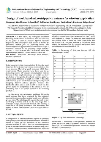
2. ANTENNA DESIGN A configuration of reference antenna is given in figure (1) and figure (2) and the result of the reference antenna is shown in figure (4).The dimension of the reference antenna is shown in table -1.Here the size of the ground plane is 50mm×50mm and the size of the radiating patch is 25mm×25mm.the antenna is mounted on FR4 substrate © 2017, IRJET
|
Impact Factor value: 5.181
|
Figure 1: Top view of reference Antenna [3] In the table -2 dimensions of the proposed antenna are given and bottom view of proposed antenna is shown in figure (3).The results of the proposed antenna are shown in figure (5) and figure (6). ISO 9001:2008 Certified Journal
|
Page 274