International Research Journal of Engineering and Technology (IRJET)
e-ISSN: 2395 -0056
Volume: 04 Issue: 02 | Feb -2017
p-ISSN: 2395-0072
www.irjet.net
Automatic Power Factor Controller(APFC) with GSM Prof. S.M.Chaudhari1, Pooja Beek2, Varsha Padalkar3, Rupali Barge4, Aishwarya Bhavsar5 1 HOD
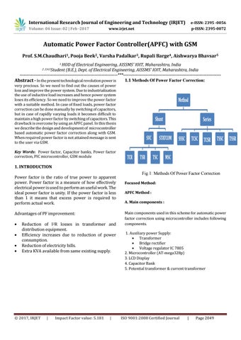
of Electrical Engineering, AISSMS' IOIT, Maharashtra, India (B.E.), Dept. of Electrical Engineering, AISSMS' IOIT, Maharashtra, India ---------------------------------------------------------------------***--------------------------------------------------------------------1.1 Methods Of Power Factor Correction: Abstract - In the present technological revolution power is 2 ,3,4,5Student
very precious. So we need to find out the causes of power loss and improve the power system. Due to industrialization the use of inductive load increases and hence power system loses its efficiency. So we need to improve the power factor with a suitable method. In case of fixed loads, power factor correction can be done manually by switching of capacitors, but in case of rapidly varying loads it becomes difficult to maintain a high power factor by switching of capacitors. This drawback is overcome by using an APFC panel. In this thesis we describe the design and development of microcontroller based automatic power factor correction along with GSM. When required power factor is not attained message is sent to the user via GSM. Key Words: Power factor, Capacitor banks, Power factor correction, PIC microcontroller, GSM module
1. INTRODUCTION Power factor is the ratio of true power to apparent power. Power factor is a measure of how effectively electrical power is used to perform an useful work. The ideal power factor is unity. If the power factor is less than 1 it means that excess power is required to perform actual work. Advantages of PF improvement:
Reduction of I2R losses in transformer and distribution equipment. Efficiency increases due to reduction of power consumption. Reduction of electricity bills. Extra KVA available from same existing supply.
© 2017, IRJET
|
Impact Factor value: 5.181
|
Fig 1: Methods Of Power Factor Correction Focused Method: APFC Method : A. Main components : Main components used in this scheme for automatic power factor correction using microcontroller includes following components. 1. Auxiliary power Supply: Transformer Bridge rectifier Voltage regulator IC 7805 2. Microcontroller (AT-mega328p) 3. LCD Display 4. Capacitor Bank 5. Potential transformer & current transformer
ISO 9001:2008 Certified Journal
|
Page 2049