INTERNATIONAL RESEARCH JOURNAL OF ENGINEERING AND TECHNOLOGY (IRJET) VOLUME: 04 ISSUE: 02 | FEB -2017
E-ISSN: 2395 -0056
WWW.IRJET.NET
P-ISSN: 2395-0072
Three Phase AC to DC Boost Converter Using D-Q Theory MAHADEV R. HADIAL Department of Electrical Engineering Vadodara Institute of Engineering Gujarat, India. ----------------------------------------------------------------------------***----------------------------------------------------------------------------Abstract—Thyristor Bridge rectifiers are employed The merits of the current controlled boost converter to obtain dc regulated voltage from ac main. These are: rectifiers are inject harmonics in the utility, it has It is provides near sinusoidal currents, thus been overcome by passive or active filter but it is avoiding expensive low harmonics filters costly and bulky.This paper presents three phase AC It is accomplished of unity power factor to DC boost bidirectional converter using DQ theory operation thus offering the option of power based current control loop. This converter provide factor compensation constant DC boost voltage from 3 phase AC voltage by closed loop control. This converter has boosted DC voltage with unity input power factor and harmonics free source current. Results are obtained Sa+ Sb+ Sc+ by computer simulation/MATLAB. R L
AC
Index Terms— bidirectional converter, DQ theory, harmonics, power factor correction.
C AC
Earlier time thyristor Bridge rectifiers are employed to obtain dc regulated voltage from ac main. These rectifiers pollute the utility with low-order harmonics, which are difficult to filter. The continuous use of thyristor Bridge rectifiers injects current harmonic components into the power grid and increases reactive power demands and power system voltage fluctuations. Harmonic current components create several problems like Increase in power system losses. Oscillatory torques in rotating machinery. Significant interference with communication circuits that share common right-ofways with AC power circuits, Overheating and insulator failures in transformers, rotating machinery, conductor and cables. Generates noise on regulating and control circuits causing erroneous operation of such equipment. Reactive power burden, low system efficiency, poor power factor, system unbalance and causes excessive neutral currents. Malfunctioning of the protective relays and untimely tripping, Failure of capacitor banks [4]. Modern three phase AC to DC converter researches have focused on providing a good input power factor and low line current harmonics distortion in order to satisfy different harmonic standards [2][4]. The PWM bidirectional converter draws a near sinusoidal input current while providing a regulated output dc voltage and can operate in the first and second quadrants of the voltage–current plane. Mostly, the control structure of a three-phase six switch PWM boost converter consists of an inner current and an outer voltage control loop
|
Impact Factor value: 5.181
Vdc L
AC
I. INTRODUCTION
© 2017, IRJET
+
Sa-
Sc-
Sb-
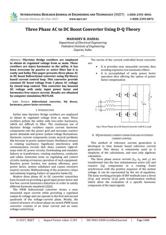
Fig.1 Three Phase AC to DC Boost Converter with R-L Load
II. DQ REFERENCE CURRENT GENERATION AND HYSTERESIS CURRENT CONTROL
This method of reference current generation is developed in time domain based reference current generation. This theory is extensively used as it simplicity of the calculations, and uses only algebraic calculation. The three phase source current (Isa, Isb, and sc) are transformed into the two instantaneous active (id) and reactive (iq) components in a rotating frame synchronous with the positive sequence of the system voltage. It can be represented by the set of equations. The basic working principle of SRF methods uses a direct (d-q) and inverse (d-q) park transformation method, which allow the evaluation of a specific harmonic component of the input signals.
|
ISO 9001:2008 Certified Journal
|
Page 1484