International Research Journal of Engineering and Technology (IRJET)
e-ISSN: 2395 -0056
Volume: 04 Issue: 01 | Jan -2017
p-ISSN: 2395-0072
www.irjet.net
A REVIEW PAPER ON CLOSED LOOP CONTROL OF BLDC MOTOR USING FUZZY LOGIC Jayesh S. Sawai1, Akash V. Rathod2, Prof. Apurva A. Bhalerao3 1Student,Department
of Electrical Engineering Department of Electrical Engineering 3Prof. Apurva A. Bhalerao, Department of Electrical Engineering, DES’s college, Maharastra, India 2Student,
---------------------------------------------------------------------***---------------------------------------------------------------------
Abstract –
different sensors can cause undesirable imbalance in phase currents. These drawback can be removed by using the single current source on DC link. For developing sophisticated control system fuzzy logic is one of the best technology in today Several studies show, both in simulations and experimental results that fuzzy logic control yields superior results with respect to those obtained by conventional control algorithms. Thus in industrial electronics the fuzzy logic are used to control the electric motor drive.in this paper, simulation by using Fuzzy logic controller is presented The fuzzy logic toolbox in MATLAB is used to design fuzzy logic controller, which is integrated into simulations with Simulink. The hardware implementation of the fuzzy logic controller is done using PIC16F877A. The hardware results show that the fuzzy logic controller gives a smooth speed control.
In this paper, a fuzzy logic controller for the Closed loop control of BLDC motor is used. The fuzzy logic controller is used from a fuzzy logic toolbox in MATLAB. A single current sensor technique is used for closed loop current control. For closed loop current control of BLDC motor, the motor phase currents are measured using current sensors. These sensors are expensive and the use of different current sensors can cause undesirable imbalance in phase currents due to differences in current sensor sensitivities. These drawbacks can be avoided by using a single current sensor placed on the DC link. Here an algorithm is presented to obtain the phase current values from the DC link current. The proposed system was simulated using MATLAB/Simulink, with PI and fuzzy logic speed controllers. The simulation result shows that, the fuzzy logic controller gives better performance than PI controller.
2. TECHNIQUES USED TO CONTROL BLDC MOTOR
Keywords: Brushless DC (BLDC) motor, fuzzy logic,
2.1. Fuzzy Logic Controller
current sensor, DC link, closed loop control
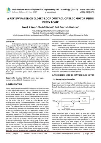
Fuzzy logic control (FLC) is a control algorithm based on a linguistic control strategy which tries to account the human knowledge about how to control a system without requiring a mathematical model. Input and output are non-fuzzy values. The block diagram of the FLC is shown in Fig. 1.
1. INTRODUCTION There is wide application of BLDC motor in industry because of their high power density and it is easy for controlling. The BLDC motor are used in a servo, robotics and domestic application because of its high efficiency, low maintenance, good speed torque characteristics and its low rotor inertia. Because of permanent magnet are on the rotor and winding on the stator, the BLDC motor are also known as AC synchronous motor. Permanent magnet creates a rotor flux and the energized stator winding create a electromagnetic poles. The energized stator phase attracts the rotor by using the appropriate sequence to supply the stator phases. This action is a fundamental action in a permanent magnet BLDC motor. The rotor position information is necessary for the successful operation of BLDC motor. The phase windings are switched in a sequence to obtain the rotation according to the rotor position. A current control loop is used in a BLDC drives to maintain the load current at some desired level, this is done by switching the constant DC link voltage across the motor windings. The current control loop is provided by direct measurement of the winding current by using separate current sensor. But the current sensor are costly But the current sensors are expensive and the use of
© 2017, IRJET
|
Impact Factor value: 5.181
Fig. 1. Block diagram of fuzzy control system
Here Mamdani type of fuzzy logic is used for speed controller. Speed error (e) and change of speed error (ce) are the inputs to fuzzy controller. The speed error is calculated by comparing the reference speed ( ref ω ) with the actual speed (ω). The output of the controller is considered as a reference current ( ref i ). The triangular shaped functions are chosen as the membership functions due to the resulting best control performance and simplicity. The membership function for speed error, change in speed
|
ISO 9001:2008 Certified Journal
| Page 1481