International Research Journal of Engineering and Technology (IRJET) Volume: 04 Issue: 02 | Feb -2017
e-ISSN: 2395 -0056
www.irjet.net
p-ISSN: 2395-0072
IOT BASED FUEL MONITORING FOR FUTURE VEHICLES. Prof.J.N.Nandimath,Varsha Alekar, Sayali Joshi, Sonal Bhite, Pradnya Chaudhari.
Department Of Computer Engineering STES, Smt Kashibai Navale College Of Engineering, Pune Savitribai Phule Pune University -----------------------------------------------------------------------***-------------------------------------------------------------------------------------Abstract—In today's world, actual record of fuel filled and fuel consumption in vehicles is not maintained. It results in a financial loss. To avoid this we are implementing an IOT fuel monitoring and tracking system. We can use the reed switch which works according to the principle of Hall Effect for sensing the amount of fuel filled in the vehicle. So as soon as agent starts filling petrol in your bike/car, the flow sensor is activated. This flow sensor will be active till flow ends. Once flow ends it will calculate the amount of fuel filled and directly notify on your mobile phone. If the phone is not available then it will store this data on cloud. Keywords: Reed Switch, Flow Sensor ,IoT ,Flow rate, Tail pipe emission.
I.
In other words: • Sensor Frequency (Hz) = 7.5 * Q (Litres/min) • litres = Q * time elapsed (seconds) / 60 (seconds/minute) • litres = (Frequency (Pulses/second) / 7.5) * time elapsed(seconds)/60
•
litres = Pulses / (7.5 * 60) Once the flow started, application will start
reading pulses and convert it into litres and then send to cloud server. Mobile application will also track location where fuel has been deposited.
INTRODUCTION Flow sensor is typically output of pulses proportional to the instantaneous flow rate which means that to interpret them it is necessary to implement simple frequency counter. Since this project uses a fuel flow sensor containing a Hall Effect sensor that output a pulse rate proportional to flow rate, so not only it is a useful project in its own right but it also demonstrates a very useful technique that you can use in a wide range of projects that need to measure the rate at which something happens (an electronic wind instrument, for example). Flow rate can be determined by different techniques like change in velocity or kinetic energy. Here we have determined flow rate by change in velocity of fuel. Velocity depends on the pressure that forces the through pipelines. As the pipes cross-sectional area is known and remains constant, the average velocity is an indication of the flow rate. The basis relationship for determining the liquid flow rate in such cases is Q=V x A, where Q is flow rate/total flow of fuel through the pipe, V is average velocity of the flow and A is the cross-sectional area of the pipe (viscosity, density and the friction of the liquid in contact with the pipe also influence the flow rate of fuel).
• •
Pulse frequency (Hz) = 7.5Q, Q is flow rate in Litres/minute Flow Rate (Litres/hour) = (Pulse frequency x 60 min) / 7.5Q
© 2017, IRJET
|
Impact Factor value: 5.181
|
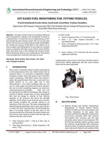
Fig 1. Flow Sensor
II.
RELATED WORK [1]
Optimal Energy and Catalyst Temperature Management of Plug-in Hybrid Electric Vehicles for Minimum Fuel Consumption and Tail-Pipe Emissions. In this paper, they develop a method to synthesize a supervisory power-train controller (SPC) that achieves near-optimal fuel economy and tail pipe emissions under known travel distances. We first find the globally optimal solution using the dynamic programming (DP) technique, which provides an optimal control policy and state trajectories. Based on the analysis of the
ISO 9001:2008 Certified Journal
|
Page 1361