International Research Journal of Engineering and Technology (IRJET) Volume: 04 Issue: 02 | Feb -2017
www.irjet.net
e-ISSN: 2395 -0056 p-ISSN: 2395-0072
Fuzzy Controller for Speed Control of BLDC motor using MATLAB Jahir Abbas Mullick PG Scholar, Dept. of Electrical Engineering, NITTTR ,KOLKATA,West Bengal, India ---------------------------------------------------------------------***---------------------------------------------------------------------
Abstract – Brushless DC Motors are used in various
applications like robotic application and space application due to small volume , highe torque and low maintenance.PWM base motor current control is implemented with the help of three hall sensors placed around the motor shaft and a three phase inverter model is implemented for motor commutation. The modeling, simulation and control of BLDC Motor have been done in MATLAB\SIMULINK software.
1.1.
MODELLING AND SIMULATION
1. INTRODUCTION
Va = R * ia + L *
+ea
(1)
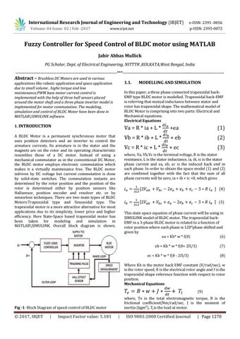
A BLDC Motor is a permanent synchronous motor that uses position detectors and an inverter to control the armature currents. Its armature is in the stator and the magnets are on the rotor and its operating characteristic resembles those of a DC motor. Instead of using a mechanical commutator as in the conventional DC Motor, the BLDC motor employs electronic commutation which makes it a virtually maintenance free. The BLDC motor isdriven by DC voltage but current commutation is done by solid-state switches. The commutation instants are determined by the rotor position and the position of the rotor is determined either by position sensors like Hallsensor, position encoder and resolver etc. or by sensorless techniques. There are two main types of BLDC Motors:Trapezoidal type and Sinusoidal type. The trapezoidal motor is a more attractive alternative for most applications due to its simplicity, lower price and higher efficiency. Here State-Space based trapezoidal motor has been taken for modeling and simulation in MATLAB\SIMULINK. Overall block diagram is shown.
Vb = R * ib + L *
+ eb
(2)
Vc = R * ic + L *
+ ec
(3)
In this paper, a three phase connected trapezoidal backEMF type BLDC motor is modelled. Trapezoidal back-EMF is referring that mutual inductance between stator and rotor has trapezoidal shape. The mathematical model of BLDC Motor is comprising into two parts: Electrical and Mechanical equations. Electrical Equations
where, Va, Vb,Vc is the terminal voltage, R is the stator resistance, L is the stator inductance, ia, ib, ic is the stator phase current and ea, eb, ec is the induced back emf in each phase. In order to obtain the space model (1) and (2) are combined together with the fact that the sum of all phase currents will be zero, ia + ib + ic =0, which gives
(4) (5) This state space equation of phase current will be using in SIMULINK model of BLDC motor. The trapezoidal backEMF in a 3-phase BLDC motor is related to a function of rotor position where each phase is 120°phase shifted and given by ea = Kb* w * f(θ) (6) eb = Kb * w * f(θ+ 2Π/3)
(7)
ec = Kb * w * f(θ - 2Π/3)
(8)
Where Kb is the motor back EMF constant (V/rad/sec), w is the rotor speed, θ is the electrical rotor angle and f is the trapezoidal shape reference function with respect to rotor position. Mechanical Equations (9) where, Te is the total electromagnetic torque, B is the frictional coefficient(Nm/rad/sec, J is the moment of inertia (kgm²), is the load at motor.
Fig -1: Block Diagram of speed control of BLDC motor
© 2017, IRJET
|
Impact Factor value: 5.181
|
ISO 9001:2008 Certified Journal
| Page 1270