International Research Journal of Engineering and Technology (IRJET)
e-ISSN: 2395-0056
Volume: 12 Issue: 06 | Jun 2025
p-ISSN: 2395-0072
www.irjet.net
Fully Autonomous Precision Drone Landing and Recharging Himanshu Negi1, Mr. Sambhav Agrawal2 1M.Tech, Computer Science and Engineering, SR Institute of Management & Technology, Lucknow, India
2Associate Professor, Computer Science and Engineering, SR Institute of Management & Technology, Lucknow
---------------------------------------------------------------------***---------------------------------------------------------------------
Abstract - This research addresses the critical challenge of
contact-based charging, and wireless charging. Battery swapping offers quick turnaround but adds mechanical complexity. Contact charging is efficient but vulnerable to environmental contamination. Wireless Power Transfer (WPT) eliminates exposed contacts, boosting reliability in harsh conditions. However, WPT demands millimetre-level landing precision for effective operation.
ensuring drones remain flight-ready in remote and demanding environments by enabling fully autonomous landing and wireless recharging without human involvement. The study emphasizes the need for a robust, weather-resistant power transfer system and explores the use of advanced resonant wireless power transfer (WPT) techniques tailored for aerial platforms. To facilitate reliable charging, a three-stage precision landing mechanism is designed and implemented. The investigation includes over a hundred autonomous flight and charging cycles, assessing the positional accuracy required for effective energy transfer. The work provides valuable insights into both hardware integration and autonomous navigation, contributing to the development of resilient, self-sustaining drone systems capable of extended deployment.
1.2 Wireless Charging Wireless Power Transfer (WPT) enables drones to recharge without physical connectors, using magnetic resonance for energy transfer across an air gap. Precision in landing is critical, as misalignments can severely reduce charging efficiency. Designs like LCC-S topology offer stability across varying loads and minor misalignments. However, standard WPT systems often ignore drone-specific challenges like frequency splitting. Studies show large misalignments drastically lower power transfer, highlighting the need for enhanced alignment methods. This research focuses on achieving millimetre-level landing accuracy to enable reliable, contactless drone recharging in real-world environments.
Key Words:
Wireless Power Transfer (WPT), LCC-S Topology, GPS-Based Navigation, UAV Self-Charging, LiPo Battery Charging, UAV Landing Accuracy, Drone-on-Cone Testing
1.INTRODUCTION Despite their potential, drones have yet to become a mainstream solution for tasks like package delivery or routine surveillance. This is largely due to regulatory constraints and significant operational challenges. In particular, systems that require manual retrieval, charging, and redeployment reduce the efficiency and practicality of drone use. This research aims to overcome these limitations by making drones instantly deployable and fully autonomous. It explores the requirements for high-precision autonomous landing and reliable wireless recharging in rugged, remote environments where human intervention is minimal or impossible. By addressing these key challenges, the study paves the way for truly independent drone operations in real-world scenarios.
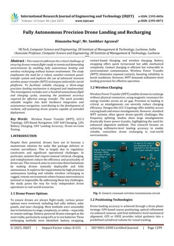
Fig -1: Generic resonant wireless transmission circuit
1.1 Drone Power Options
1.2 Positioning Technologies
To ensure drones are always flight-ready, various power options were reviewed, including fuel cells, tethers, solar panels, and laser charging. Most methods were unsuitable due to limitations in range, complexity, or safety—especially in remote settings. Battery-powered drones emerged as the most viable, particularly using LiPo or Li-ion batteries. Three recharging methods were identified: battery swapping,
© 2025, IRJET
|
Impact Factor value: 8.315
Drone landing accuracy is achieved through a three-phase strategy: GPS-based coarse positioning, optical refinement via onboard cameras, and final millimetre-level mechanical alignment. GPS or GNSS provides initial guidance into a predefined cylindrical volume for visual tracking.
|
ISO 9001:2008 Certified Journal
|
Page 1299