
International Research Journal of Engineering and Technology (IRJET) e-ISSN:2395-0056
Volume: 12 Issue: 05 | May 2025 www.irjet.net p-ISSN:2395-0072
![]()

International Research Journal of Engineering and Technology (IRJET) e-ISSN:2395-0056
Volume: 12 Issue: 05 | May 2025 www.irjet.net p-ISSN:2395-0072
S. Gajendran1, G. Prabhakaran2
P.G. scholar, Department of ECE, Nandha Engineering College, Erode, Tamilnadu, India1 Assistant Professor, Department of ECE, Nandha Engineering College, Erode, Tamilnadu, India2
Abstract: Compact Space and Minimal Power VLSI circuits are the standard for creating energy-efficient, high-performance, and small devices. Digital signal processing, microprocessors, and microcomputer applications all heavily rely on multipliers. In this design, we analysed and compared various multiplier types, including Wallace trees, arrays, and Booth multipliers. By using partial product reduction, multipliers can be designed to increase the creation of complex circuits and their analysis. Any algorithm for multiplying integers should aim to minimise the partial product summation. Among the most well-liked and effective algorithms is the Boothtechnique.
Keywords: Array, Wallace and Booth multipliers, Encoding,Decoding,CSA,MAC,CPA
1. Introduction
Multipliers are essential for processing digital signals in real time as well as for several other processes. Thedesignofmultipliersthatofferincreased speed, reduced power consumption, regular layout and, therefore,asmallarea,orevenacombinationofthesein a single multiplier,has been attempted and is still being attemptedbynumerousresearchers.
This makes the multipliers applicable for a varietyofincreasedspeed,reducedpower,andcompact VLSI prosecutions. The Booth technique and the Modified Booth algorithm, which minimise the partial products(1).Itisevidentthatthereisadesirefordesign patterns for digital systems that have low power consumption and high increment (2). We propose to redesign the existing. We suggest utilising a carry to redesign the becoming twofold multipliers. We propose toredesigntheexisting.Byemployingacarrylookahead adder, we suggest redesigning the being double multipliers. We obtain an efficient design in terms of detention optimisation by employing this method. The suggested approach produces a superior result in relative research where some of the variables are multipliers (3), (4). Verilog HDL is used to enforce the designs.
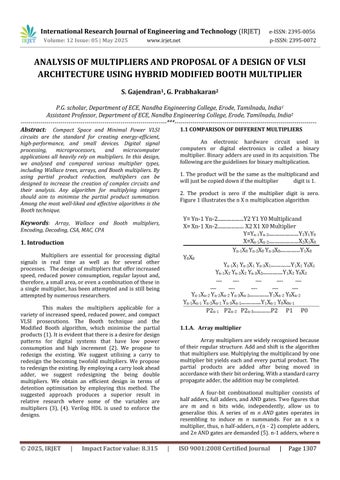
An electronic hardware circuit used in computers or digital electronics is called a binary multiplier.Binaryaddersareusedinitsacquisition. The followingaretheguidelinesforbinarymultiplication.
1. The product will be the same as the multiplicand and willjustbecopieddownifthemultiplier digitis1.
2. The product is zero if the multiplier digit is zero. Figure1illustratesthenXnmultiplicationalgorithm

Arraymultipliersarewidelyrecognisedbecause oftheir regular structure. Addand shift is the algorithm thatmultipliersuse.Multiplyingthemultiplicandbyone multiplier bit yields each and every partial product. The partial products are added after being moved in accordancewiththeirbitordering.Withastandardcarry propagateadder,theadditionmaybecompleted.
A four-bit combinational multiplier consists of halfadders, fulladders,andANDgates.Twofiguresthat are m and n bits wide, independently, allow us to generalise this. A series of m n AND gates operates in resembling to induce m n summands. For an n x n multiplier,thus,nhalf-adders, n (n-2)completeadders, and2n ANDgatesaredemanded(5).n-1adders,wheren

International Research Journal of Engineering and Technology (IRJET) e-ISSN:2395-0056
Volume: 12 Issue: 05 | May 2025 www.irjet.net p-ISSN:2395-0072
isthemultiplierlength,aredemanded.Asdemonstrated by this illustration, the addition is performed both in resembling and serially, despite the system's simplicity. One debit is that the tackle gets more complicated and takes up more space because so many gates are used, anditislesseconomical[6].
A digital circuit's attack performance that adds two double digits is called a Wallace tree multiplier. Everycolumnthathasasquaremeasureoftwobitsuses half adders' square measure, while every column that has a square measure of three bits uses full adders' square measure. Any bitthatispresentinthecolumnis movedtothenextstageinthesamecolumnwithoutany procedures. Repeat this technique until there are just tworowsleft. Thesquaremeasuresofthelasttworows are value-added within the finish. Eight small pieces of affairs are typically obtained after completing all three stages. The circuit diagram for the Wallace Tree Multiplier using half and full adders were shown in Fig. 2. Straightforward, as demonstrated by this illustration

In the first step, partial products are created by multiplyingeachbitofthemultiplicandbyeachbitofthe multiplier. The length of the multiplicand is therefore usedtocomputethenumberofpartial products.[7],for each column with two bits, a half adder is utilised, and for each column with three bits, a full adder. Any single bitinthecolumnistransferred, withoutanyprocessing, to the next step in the same column. Every step of the reduction process is repeated until there are just two left. In [8] the final step involved adding the two remaining rows. We obtain an output of 8 bits once all three processes have been completed. The example schemeisdisplayedinFigure2.
This figure illustrates the arrangement of the Wallacetree,whichhascarriedsaveadders.Acarrysave adder(CSA)generatesasecondresultwhiletheadderis still complete by bringing out the carry output of each bit. Enhancement of worst-case path delay is the aim of CSA [9]. It uses a 4-bit to implement CSA. The second addition uses the carry input from the first addition. Increasing the maximum frequency is one of CSA's benefits[10].
A sequence of complete adders, each one a singlebit,isusedinthetraditionalCSAtreetogradually reduce partial product bits with numerous inputs at the samebitpositiontoafinalsumandcarrypair.Afterthe output, we will have a sum and carry, which a carrypropagate adder (CPA) must add. Radix-8 recoding is fasterthanradix-4recoding,whichutilises n/2, because itreducesthepartialproductston/3fornbits[11].
Acrucial component of digital signal processing (DSP) systems is booth multipliers. Recursive and transversal filter implementations make use of them. In contrast to add shift algorithms, which require less hardware and perform worse, conventional array multipliers, reach relatively acceptable performance but requireavastsiliconarea.Theoperationisreducedtoa partial product summation in any multiplication algorithm.
Each partial product indicates a multiplicand multiple that ought to be included in the outcome [12]. Inordertoachieveaspeedadvantageoverconventional multiplier architectures, the Booth multiplier uses the Booth encoding technique [13] to limit the partial products by taking into account two multiplier bits at a time.Aclevermethodformultiplyingsignednumbersis Booth'sAlgorithm. Theabilitytoaddand subtractisthe firststep.[14]
Whilestudyingcrystallographyin1950,Andrew Donald Booth created the Booth algorithm. The Booth multiplier achieves a speed advantage over existing multiplier architectures by using the Booth encoding technique to limit the partial products. An intelligent method for multiplying signed numbers is Booth's algorithm.Beingabletoaddandsubtractisthefirststep. Itusesthe encodingof2'scomplementtohandlesigned binary multiplication [15]. The process by which operand signs are stored in auxiliary circuits becomes moreintricateasaresult.Itisahighlyusedalgorithmfor multiplication of signed numbers that uniformly takes intoaccountbothpositiveandnegativenumbers[16].

International Research Journal of Engineering and Technology (IRJET) e-ISSN:2395-0056
Volume: 12 Issue: 05 | May 2025 www.irjet.net p-ISSN:2395-0072

ArchitectureofBoothMultiplier
1.2.A. Radix 4 Booth Multiplier
The Booth technique [17] is an effective algorithm for multiplication of signed numbers. It can handle more than one bit of the multiplier in each cycle byemployinghighradixmultiplication[18]TheRadix-2 algorithm's drawbacks are all addressed by the Radix-4 modifiedBoothalgorithm.
Modified Booth Multiplier
The enhanced Booth multiplier is known as the modified Booth multiplier [19]. In the Modified Booth, the quantity of partial items produced is cut in half. To achieve the same results, multiply every second column by ±1, ±2, or 0 rather than shifting and adding each columnofthe multipliertermandthenmultiplyingby 1 or0. Bit

pairingasperbitencoding
Themultiplicandisencodedusingthemultiplier bits by the radix-4 booth encoder. It will use the overlapping approach to compare three bits at a time. Thefirstblock,asshowninFig.3,assumesazeroforthe third bit and uses only two of the multiplier's bits. TroupingstartsattheLSB.
Table 1 displays Radix-4 booth encoder's operationalstate.Thereareeightvariouskindsofstates in it, and we can get the results of multiplying the multiplicandby0,-1,and-2inthatorder.
Table 1.BoothrecordingtableforRadix–4

Radix-4BoothalgorithmforBoothEncoding isgiven below:
1)Ifnecessary,changethesignbitonepositionto ensurethatniscorrect.
2)Placeazerotothemultiplier'srightoftheLSB.
3)Inlinewitheachvector'svalue.Therewillbe0,X,-X, 2X,or-2Xforeachpartialproduct.
1.2.B.Radix 8 Booth Encoding :
The main difference between radix 8 Booth recoding and radix 4 Booth recoding is the use of quartets of bits rather than triplets. Radix 8 reduces the partialproductston/3.Ourmultiplier,however,ismade to be modified at the earlier phases of the adder. With the exception of employing quartets of bits rather than triplets, the algorithm for Radix-8 Booth recoding is the sameasforRadix-4Boothrecoding
Table 2. BoothAlgorithmRadix8truthtable


International Research Journal of Engineering and Technology (IRJET) e-ISSN:2395-0056
Volume: 12 Issue: 05 | May 2025 www.irjet.net p-ISSN:2395-0072
TheBoothmultiplierconsistsofthreebasicunitcells:
Encoder
The encoder circuit's general structure is the double law that the affair lines produced in response to theinputvalue.
Decoder
An array of inputs and labors in a sense circuit known as a decoder converts encoded inputs into encodedlaborsindeedwhentheinputandaffaircanons are different. With n possible labors and 2n inputs, it presentsthedecoderdata.
12-bit adder
The 4-bitcarry lookahead adder with the4-bit fulladdercomprisesthe12-bitaddercircuit.
Acompleteadderisathree-bitcolumnaddition circuit. Given that the final addition time greatly increases the multiplier's critical path, it is obvious that the quickest method ought to be applied [20]. The current structure is changed by replacing the final completeadderstagewithacarrylookaheadadder.

Fig.4. 4-bitCarrylookaheadadder
4- bit Carry look ahead Adder
Generating and propagating carries are ideas used in carry look-ahead logic. In order to ascertain the carry in advance, the circuit may "pre-process" the two integers being added. By doing this, there's no longer a needtostayfortheadditiontoactuallytakeeffect.Every functionthatgeneratesandpropagatesisstatedinterms of the entire adders' inputs, rather than waiting for the carry to ripple through each stage; all of the labors are now incontinently available (21). After making a few
minor adjustments, the basic 4-bit generalised Carry LookAheadcircuitmaybeconnectedtothe4-bitRipple CarryAdderthatweinitiallyutilised.
Both of radix-4 and radix-8 multipliers were designed by using the Modified Booth Algorithm. The Radix-8 Modified Booth Multiplier outperforms the Radix-4 Modified Booth Multiplier. Thus, the radix-8 multiplier had a shorter time period than the radix-4 multiplier.
The system's energy consumption and presto operation are measured by the MAC unit. The MAC unit is a pivotal element of the signal processing unit. The final step in that design is to build a multiplier accumulator (MAC) unit for high-speed digital signal processing.
The sum of an accumulator, multiplier, and adder is known as MAC. The multiplier factor block performs the addition operation after we recoup the multiplier and accumulator input from the memory address. Data is subsequently transferred to the adder, which compiles all of the data before storing it in a memory position. Several addition styles, analogous to bit-quotidian,journal-parallelorfull-similarapproaches, can be used to produce partial products. For this, the Booth or modified Booth algorithms are generally employed.
The architecture of the multiplier is separated into three stages: partial product reduction, partial product generation, and the supplementary reduced partial product stage. Multiplications have historically beendoneusingtheshiftandaddalgorithm(22).
AmodifiedBooth-encodedhybridmultiplierand a parallel hybrid adder will be used in the suggested design. The design goal of the proposed MAC (Multiply andAccumulate)unitistoachieveefficiencyinbotharea and power. Both a hybrid multiplier and a hybrid adder areemployed,alongwithachangedencodingscheme.
The16-bitmultiplier(B(15:0))andmultiplicand (A(15:0)) are the system's inputs. The Modified Booth garbling blockprocessestheseinputsinordertoreduce the partial products. Booth garbling does this by combiningandgarblingthemultiplier'sbitsinawaythat decreasesthetotalnumberofoperationsrequired.
The encoding process is followed by the pipelining block for partial products receiving the

International Research Journal of Engineering and Technology (IRJET) e-ISSN:2395-0056
Volume: 12 Issue: 05 | May 2025 www.irjet.net p-ISSN:2395-0072
encoded outputs. This simultaneous processing greatly increases the multiplication process's total speed. Anotherimportantpartofthisarchitectureisconditional gating.Powerconsumptionisefficientlymanagedbythis block, which regulates data flow according to predeterminedcriteria. The outputis the32-bit product result of the multiplication. is the last element and is denoted bythesymbol Y[31:0].Following completionof eachpipelinestage,theendresultisthecumulativesum ofthePPs.
ThedevelopedMACdesigniscomprisedofthree phases: design entry, simulation, and synthesis The suggested design has been built in Verilog, and its functioning has been confirmed using the Cadence NCSim simulator. After the functional verification is finished,theoptimisednetlistisinspectedusingtheRTL model in the Genus Synthesis Tool to obtain data on time, power, area, and other variables. Referred papers arecomparedwiththeseareas,power,etc.
The suggested MAC (Multiply-Accumulate) unit is very efficient in terms of both power and area. The design essentially combines a Booth multiplier with a mongrel adder, with each optimised for its own capabilities. The mongrel multiplier uses a modified garbling strategy to reduce area while increasing speed, whilst the mongrel adder, built using a mix of CSA and CLA,playsanimportantroleinminimisingpowerusage and further lowering area. The suggested MAC unit worksbetterthanconventionaldesigns,assupportedby previous articles, as demonstrated by the whole armature, which was encoded in Verilog and validated using the meter NCSim simulator. Finally, as confirmed by both simulated and synthesised findings, the armature of this suggested MAC unit exhibits an optimisingbalanceofpower&areaefficiency.
[1] Prasanna Raj P, Rao, Ravi, ―VLSI Design and Analysis of Multipliers For Low Power, Intelligent Information Hiding and Multimedia Signal Processing,FifthInternationalConference,pp.:13541357,Sept.2009.
[2] AnanthaP.Chandrakasan,SamuelSheng,Robert W.Brodersen"Low-PowerCMOSdigitaldesign,"IEEE JournalofSolidStateCircuits,Vol.27,No.4,1992.
[3] Kelly Liew Suet Swee, Lo Hai Hiung, "Performance Comparison Review of 32-Bit MultiplierDesigns,"IEEE,2011.
[4] Hasan Krad, Yousif Al-Taie Aws, "Performance Analysis of a 32-Bit Multiplier with a Carry-LookAhead Adder and a 32-bit Multiplier with a Ripple Adder using VHDL," Journal of Computer Science 4 (4):pp.305-308,2008.
[5] Shaik Nasar, K. Subbarao, "Design & ImplementationofMACUnitUsingReversibleLogic," International Journal of Engineering Research and ApplicationsVol.2,Issue5,pp.1848-1855,2012.
[6] Sumit Vaidya, Dandekar. D, "Delay-power performancecomparisonofmultipliersinVLSIcircuit design," International Journal of Computer Networks &Communications(IJCNC),Vol.2,No.4,2010.
[7] B. Lamba and A. Sharma, "A review paper on different multipliers based on their different performance parameter”, 2nd International Conference on Inventive Systems and Control, pp 324-327,2018.
[8] BhawnaSingroul,PallaveeJaiswal,“A reviewon performanceEvaluationdifferentdigitalmultiplierin VLSI using VHDL”, International journal of Engineering research & technology, vol-7, issue-5 , 2018.
[9] Sumit Vaidya, Deepak Dandekar, “A review on delay performance comparison of multiplier in VLSI circuit design”, International journal of computer network & communication, Vol 2, issue 4, pp 47-55, 2010
[10] Soniya, Suresh kumar, “A review of different types multiplier and multiplier accumulator unit”, International journal Emerging Trends and technology in computer science, vol-2, issue-4, pp 364-368,2013
[11] lakshmanan, m. othman, m.a.m. ali, “design and characterization of parallel prefix adders using fpgas,” journal of computers, vol. 5, no. 10, october 2012.
[12] J.A. Hidalgo, V. Moreno-Vergara, O. Oballe, A. Daza, M.J. Martín-Vázquez, A.Gago ,“A Radix-8 multiplierdesignforspecificpurpose”@2011.
[13] Kelly Liew Suet Swee, ”Performance And Comparison Review Of Radix Based Multiplier Design”, International Conference Of Intelligent And AdvancedSystem,2012
[14] Depth:In More Booth‗s Algorithm, staff.ustc.edu.cn/~han/CS152CD/Content/COD3e/in moredepth/IMD3-Booths-Algorithm.pdf–

International Research Journal of Engineering and Technology (IRJET) e-ISSN:2395-0056
Volume: 12 Issue: 05 | May 2025 www.irjet.net p-ISSN:2395-0072
[15] Abenet Getahun, ―Booth Multiplication Algorithm,‖Fall2003CSCI401
[16] A. D. BOOTH, “A signed Binary multiplication technique”, in journal of Mech. APPL. Math, Oxford Universitypress,vol-4,pp236-240,1951.
[17] Rajput.S, Shukla.R, Praveen.P, Anand.A, “Implementationofhighspeedandlowpowerhybrid adder based novel radix-4 booth multiplier”, Communication System Network Technologies, InternationalConference,2013.
[18] Premananthan.G, 2Amudha.K, 3 Sreenath.G, “A Faster Carry Save Adder in Radix-8 Booth Encoder Multiplier” ,International Journal of VLSI & Signal Processing Applications, Vol. 2,Issue2, April 2012, ISSN2231-3133,(171-175).
[19] Kim, S. and Cho, K. Design of high-speed modified booth multipliers operating at GHz ranges. World academy of science, Engineering and Technology61(2010),pp.1–4.
[20] Vojin G O, D. Villeger, Simon S L, "A Method for Speed Optimized Partial Product Reduction and Generation of Fast Parallel Multipliers Using an Algorithmic Approach," IEEE Transactions on computers,Vol.45,No.3,1996.
[21] A. Anand Kumar, "Fundamentals of Digital Circuits," pp. 242-245 PHI Learning Private Ltd. New Delhi,2008.
[22] Bhavya Lahari Gundapaneni, JRK kumar Dabbakutti, “ A review on Booth Algorithm for the design of multiplier”, International journal of innovative technology and Exploring Engineering , vol-8,issue-7,pp1506-1509,2019