
International Research Journal of Engineering and Technology (IRJET) e-ISSN: 2395-0056
Volume: 12 Issue: 05 | May 2025 www.irjet.net p-ISSN: 2395-0072


International Research Journal of Engineering and Technology (IRJET) e-ISSN: 2395-0056
Volume: 12 Issue: 05 | May 2025 www.irjet.net p-ISSN: 2395-0072
Aman Shah1 , Aakash Suthar2
1M.Tech Student, Department of Structural Engineering, L.J. University, Ahmedabad, Gujarat, India.
2Assistant Professor, Structural Engineering Department, L.J. University, Ahmedabad, Gujarat, India.
Abstract -This study presents a comprehensive seismic performance assessment of a G+12 Special Moment Resisting Frame (SMRF) structure located on sloping terrains, utilizing ETABS for structural analysis. The investigation encompasses four terrain slopes 0°, 20°, 45°, and 60° across three soil classifications: hard, medium, and soft, under seismic zones III and IV. Critical response parameters including story displacement, story drift, stiffness and strength irregularities, mass irregularity, torsional irregularity, diaphragm behavior (rigid vs. flexible), and mode shapes were evaluated to understand the influence of topographical and geotechnical variations on seismic behavior. The results show that increasing slope inclination and decreasing soil stiffness notably increase seismic demands. Structures situated on steeper slopes and softer soils exhibited greater lateral displacements, higher torsional irregularities, and more complex mode shapes, indicating a higher vulnerability to dynamic loading. Rigid diaphragm systems were found to enhance overall structuralstabilitybyreducingdeformationandcontrolling inter-story drift. This study emphasizes the significant impact of slope geometry, soil flexibility, and diaphragm type on the seismic response of multistory structures. The findings reveal the limitations of traditional design assumptionsbasedonflatgroundandhighlighttheneedfor slope-adaptive structural strategies. Such approaches are essential for ensuring the safety and performance of structures in seismically active regions with irregular topography
Key Words: Sloping ground, Soil Structure Interaction (SSI),Seismicanalysis,EquivalentStaticMethod,Response Spectrum Analysis, Seismic Zones, Slope angel variation, Storey Drift, Storey Displacement, Stiffness Irregularity, Storey Shear, Mass Irregularity, Rigid & Flexible Diaphragm,ModeShape,TorsionalIrregularity,ETABS.
Earthquakes are one of the most devastating natural hazards, capable of causing extensive damage to infrastructure, disrupting economies, and resulting in significant loss of life. Their unpredictable nature and the powerful forces they generate present substantial challenges for structural engineers, especially in regions with moderate to high seismic activity. As urban populations grow and available flat land becomes
increasingly scarce, urban development has started to expand into hilly and mountainous areas. This trend has led to the construction of mid- to high-rise buildings on sloped terrains, introducing complex engineering challenges that go beyond those faced in traditional flatlandconstruction.
Buildings located on sloping ground differ significantly in their behavior and design compared to those built on flat sites. The terrain requires stepped or terraced foundations, creating variations in elevation and support conditions across the base of the structure. This unevenness affects both the vertical load path and the distribution of stiffness throughout the building’s footprint. Additionally, sloped terrain can lead to nonuniform mass distribution due to differences in story height, column length, and the overall shape of the building envelope. These irregularities can greatly impact the building's seismic response, resulting in complex interactionsbetweenlateralandtorsionalmovementsand increasing the likelihood of structural damage during earthquakes.
Seismic design codes typically identify certain structural irregularities such as stiffness, strength, mass, and torsional irregularities as critical factors that influence dynamic performance. These characteristics are often more pronounced in hillside buildings, making them particularly vulnerable to seismic activity. For example, onesideofastructure,usuallytheuphillside,maybehave more rigidly due to shorter columns, while the downhill side may exhibit greater flexibility because of longer unsupported column lengths. This asymmetry can result in non-uniform story drifts and concentrated internal forces, especially when subjected to lateral seismic loads. Additionally, soft or varying soil conditions on sloped terrain can worsen these effects, leading to differential settlements, amplification of ground motions, and increasedbaseshear.
Besidesgeometricandgeotechnicalchallenges,diaphragm behavior plays a crucial role in hillside construction. The assumption of rigid diaphragms, which is often valid for flat terrain, may not apply in irregular or staggered layouts. Flexible diaphragms can cause disproportionate load distribution among lateral force-resisting elements, furthercomplicatingthestructuralresponse.

International Research Journal of Engineering and Technology (IRJET) e-ISSN: 2395-0056
Volume: 12 Issue: 05 | May 2025 www.irjet.net p-ISSN: 2395-0072

To tackle these challenges, a more nuanced and siteresponsive approach to structural analysis and design is necessary. Advanced computational tools, such as ETABS and other finite element-based platforms, enable detailed modeling of terrain-induced irregularities and soilstructure interactions. These tools facilitate accurate assessments of key seismic response parameters, including story displacements, inter-story drifts, base shear,modeshapes,anddynamicirregularities.
This study focuses on the seismic behavior of a G+12 SpecialMomentResistingFrame(SMRF)structurebuilton varyingslopeanglesandsoiltypes,particularlyinseismic zones III and IV. By examining how slope geometry, soil classification, and diaphragm behavior influence structural performance under seismic loading, the researchaimstoprovidecriticalinsightsforengineersand designers.Theobjectiveistoemphasizetheimportanceof slope-adaptive design methodologies that ensure both structural safety and compliance with codes, ultimately contributing to more resilient urban development in seismically sensitive and topographically challenging regions.
1. To evaluate the effect of slope angle (0°, 20°, 45°, 60°) on the seismic response of G+12 SMRF structures,usingETABSsoftware.
2. To assess key seismic response parameters, including storey displacement, storey drift, stiffness irregularity, and storey strength, in buildingsconstructedonslopingterrain.
3. To examine mass irregularity and torsional irregularity in sloped structures and their influence on overall dynamic behavior during seismicevents.
4. Toidentifythebuildingbehaviourunderdifferent soil types and slope angles, and to observe how thesevariationsaffectthemodeshape.
5. Toinvestigatetheroleofdiaphragmtype(rigidvs flexible) in controlling lateral displacement and improvingseismicstability
6. Tocomparethebuildingbehaviorunderdifferent soil types (hard, medium, soft) and analyze how soil flexibility influences structural performance duringseismicevents.
7. To assess building performance in Seismic Zones IIIandIVandunderstandhowincreasingseismic intensity impacts structural behavior, especially inbuildingswithuneventerrain.
1. Absence of Terrain-Specific Design Guidelines in SeismicCodes.
2. Inadequate Integration of Soil-Structure-Terrain Interaction(SSTI).
3. Insufficient Focus on Mode Shape Variation Due toSlope-InducedIrregularities.
4. Limited Research on Seismic Behavior of StructuresonSteepSlopes(45°–60°).
5. Neglect of Diaphragm Flexibility in Sloped BuildingPerformanceAnalysis.
This study investigates the impact of varying slope gradients (0°, 20°, 45°, and 60°) on geotechnical behavior across different seismic zones (Zone III and Zone IV) and soil types (I, II, and III), aiming to analyze the structural response and stability under diverse slope-soil-zone conditions.

1.3.1. Scope of Work
The analysis and design of a multistorey (G+12) Special Moment Resisting Frame (SMRF) building situated on

International Research Journal of Engineering and Technology (IRJET) e-ISSN: 2395-0056
Volume: 12 Issue: 05 | May 2025 www.irjet.net p-ISSN: 2395-0072
slopingterrainareconductedutilizingETABSsoftware.In ETABS, the design and analysis of reinforced cement concrete (RCC) structures are carried out through five essentialsteps:Define,Draw,Assign,Analyze,andDesign. This study evaluates the structural performance of the building across four different slope angles: 0°, 20°, 45°, and 60°, while considering three types of soil conditions: hard, medium, and soft. Furthermore, the building is examined under Seismic Zones III and IV in accordance with the guidelines outlined in IS 1893 (Part 1): 2016. A total of 24 models are created to combine variations in slope,soiltype,andseismiczone,ensuringcomprehensive data validation and a robust comparison of seismic responses. To facilitate effective analysis of these models, input parameters such as material properties, section dimensions, loading conditions, and boundary conditions are defined in accordance with the relevant Indian Standardcodes(IS456:2000,IS875,andIS1893).
DATA INPUT IN ETABS
HeightofTypicalStorey 3m
HeightofGroundStorey 3m
LengthoftheBuilding 15m
WidthoftheBuilding 13m
HeightoftheBuilding 39m
NumberofStories 13
WallThickness 230mm
SlabThickness 150mm
GradeofConcrete M25
GradeofSteel Fe500
Support Fixed
ColumnSize
BeamSize
300mmx600mm
230mmx450mm
SlopeAngel 0°,20°,45°,and60°
LocationofBuilding India
LiveLoad
AtTypicalFloor=3kN/m2
AtTerrace=2kN/m2
FloorFinish AtTypicalFloor=2kN/m2
AtTerrace=2.5kN/m2
DensityofConcrete 25kN/m3
SeismicZone ZoneIII,IV
SiteType I,II,III
ImportanceFactor 1
ResponseReduction 5
DampingRatio 5%
StructureClass C
BasicWindSpeed 47m/s
RiskCoefficient(k1) 1.00
TerrainSizeCoefficient(k2) 2.00
TopographyFactor(k3) 1.36
WindDesignCode IS:875-2015(Part-3)
RCCDesignCode IS:456-2000
SteelDesignCode IS:800-2007


International Research Journal of Engineering and Technology (IRJET) e-ISSN: 2395-0056

2.1.3. Define Grade of Steel
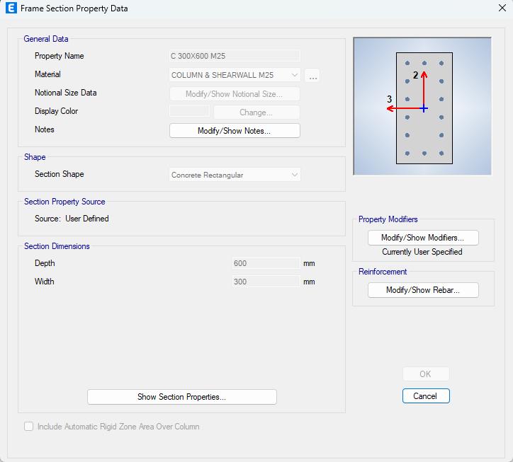
2.1.4. Section Property of Column

Figure 2.1.5. Modifiers of Column

Figure 2.1.6. Column Reinforcement Data

Figure 2.1.7. Section Property of Beam

Figure 2.1.8. Beam Reinforcement Data
Volume: 12 Issue: 05 | May 2025 www.irjet.net p-ISSN: 2395-0072 © 2025, IRJET | Impact Factor value: 8.315 | ISO 9001:2008 Certified Journal | Page1503

International Research Journal of Engineering and Technology (IRJET) e-ISSN: 2395-0056
Volume: 12 Issue: 05 | May 2025 www.irjet.net p-ISSN: 2395-0072

2.1.9. Modifiers of Beams
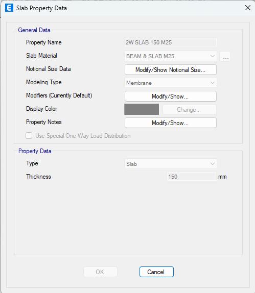
2.2. Draw
We will createa total of24modelsofG+12 withdifferent slopeangles (0°, 20°, 45°, and 60°), different soil types (I, II,andIII),andvariousseismiczones(ZoneIIIandIV).

2.2.1. Types of Model

2.2.2. 3D-Model having 0° Slope


2.2.3. 3D-Model having 20° Slope

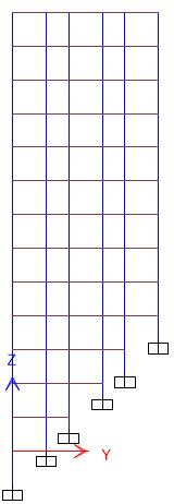
Figure 2.2.5. 3D-Model having 45° Slope

© 2025, IRJET | Impact Factor value: 8.315 | ISO 9001:2008 Certified

2.2.4. Elevation 20° Slope Model
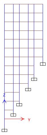
Figure 2.2.6. Elevation 45° Slope Model


International Research Journal of Engineering and Technology (IRJET) e-ISSN: 2395-0056
Volume: 12 Issue: 05 | May 2025 www.irjet.net p-ISSN: 2395-0072
2.3. ASSIGN




2.4. ANALYZE
The structural analysis of Reinforced Cement Concrete (RCC) buildings subjected to seismic forces is typically conductedusingtwomainapproaches:
1. Equivalent Static Method :
The Equivalent Static Method is a simplified procedureforestimatingtheseismicforcesacting on a structure. In this method, lateral earthquake forces are assumed to act statically and are distributed along the height of the structure according to predefined code provisions. This approach assumes that the structure primarily responds in its fundamental mode and does not accountfortorsionalorhigher-modeeffects.
Due to its simplicity and ease of use, this method iscommonlyappliedtolow-rise,regularbuildings where the structural behavior is relatively

International Research Journal of Engineering and Technology (IRJET) e-ISSN: 2395-0056
Volume: 12 Issue: 05 | May 2025 www.irjet.net p-ISSN: 2395-0072
straightforward. However, it may not yield accurate results for structures with irregular geometries, significant heights, or mass/stiffness discontinuities.
2. Dynamic Analysis Method :
Dynamic analysis is a more sophisticated approach that considers the actual dynamic characteristics of the structure, including natural frequencies, mode shapes, and damping. This method is suitable for both regular and irregular buildings and is especially important for taller or morecomplexstructures.
Dynamic analysis can be performed using one of thefollowingtechniques:
Response Spectrum Method: This method utilizes a standard response spectrum curve to estimate the peak response of the structure based on its naturalmodes.Itisalinear,modal-based approachwidelyusedindesigncodesfor seismic analysis due to its balance of accuracyandcomputational efficiency.In this study, the Response Spectrum Methodhasbeenadoptedforanalysis.
In the present study, the Response Spectrum Method has been adopted for the analysis.
Time History Method: This method involves applying actual ground motion records to the structure to evaluate its time-dependent response. It is the most detailed and computationally intensive form of dynamic analysis, capable of capturing nonlinear behavior and complexinteractions.
After completing the modeling process and assigning the necessary structural properties in ETABS, the analysis phase was carried out to assess the behavior of the structure under seismic loading conditions. The following structuralresponseparameterswerecloselyobserved:
StoreyDrift
StoreyDisplacement
StiffnessIrregularity
StoreyStrength
MassIrregularity
Diaphragm (FlexibleandRigid)
ModeShapes
TorsionalIrregularity
These parameters were selected based on their significance in evaluating the structural performance and identifying potential irregularities that may influence the dynamic response of the building. The results have been systematically compiled and are presented in the form of graphsandtablesfordetailedinterpretation.

Figure 3.1.1. Comparison of storey drift-SPEC-X-Soil Type-1-Zone-3

Figure 3.1.2. Comparison of storey drift-SPEC-X-Soil Type-2-Zone-3

Figure 3.1.3. Comparison of storey drift-SPEC-X-Soil Type-3-Zone-3

International Research Journal of Engineering and Technology (IRJET) e-ISSN: 2395-0056
Volume: 12 Issue: 05 | May 2025 www.irjet.net p-ISSN: 2395-0072

Figure 3.1.4. Comparison of storey drift-SPEC-X-Soil
Type-1-Zone-4
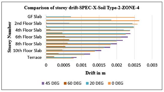
Figure 3.1.5. Comparison of storey drift-SPEC-X-Soil
Type-2-Zone-4

Figure 3.1.6. Comparison of storey drift-SPEC-X-Soil
Type-3-Zone-4
3.2. STOREY DISPLACEMENT

Figure 3.2.1. Comparison of storey displacementSPEC-X-Soil Type-1-Zone-3

Figure 3.2.2. Comparison of storey displacementSPEC-X-Soil Type-2-Zone-3

Figure 3.2.3. Comparison of storey displacementSPEC-X-Soil Type-3-Zone-3

International Research Journal of Engineering and Technology (IRJET) e-ISSN: 2395-0056
Volume: 12 Issue: 05 | May 2025 www.irjet.net p-ISSN: 2395-0072
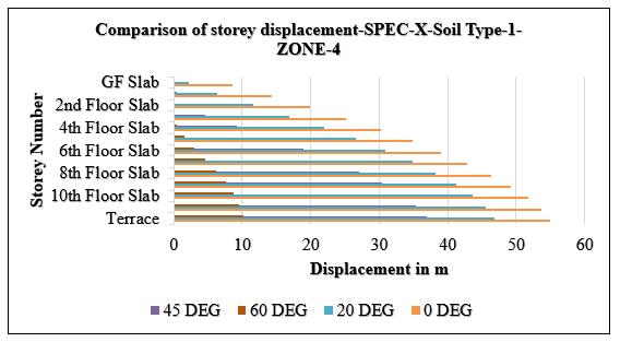
Figure 3.2.4. Comparison of storey displacementSPEC-X-Soil Type-1-Zone-4

Figure 3.2.5. Comparison of storey displacementSPEC-X-Soil Type-2-Zone-4

Figure 3.2.6. Comparison of storey displacementSPEC-X-Soil Type-3-Zone-4
3.3. STIFFNESS IRREGULARITY

Figure 3.3.1. Comparison of stiffness irregularitySPEC-X-Slope-0°-Zone-3

Figure 3.3.2. Comparison of stiffness irregularitySPEC-X-Slope-0°-Zone-4
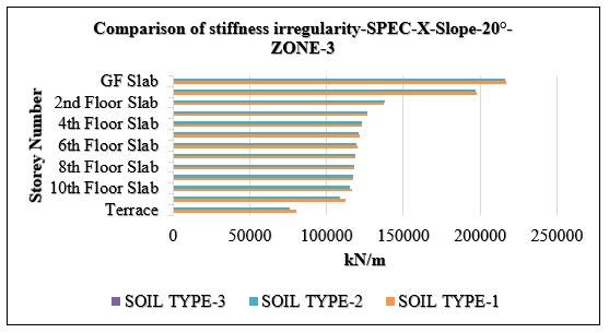
Figure 3.3.3. Comparison of stiffness irregularitySPEC-X-Slope-20°-Zone-3
2025, IRJET | Impact Factor value: 8.315 | ISO 9001:2008

International Research Journal of Engineering and Technology (IRJET) e-ISSN: 2395-0056
Volume: 12 Issue: 05 | May 2025 www.irjet.net p-ISSN: 2395-0072
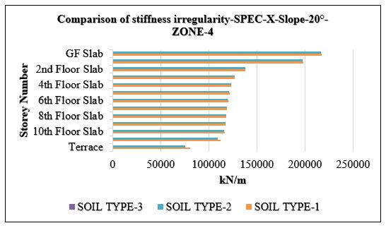
Figure 3.3.4. Comparison of stiffness irregularitySPEC-X-Slope-20°-Zone-4
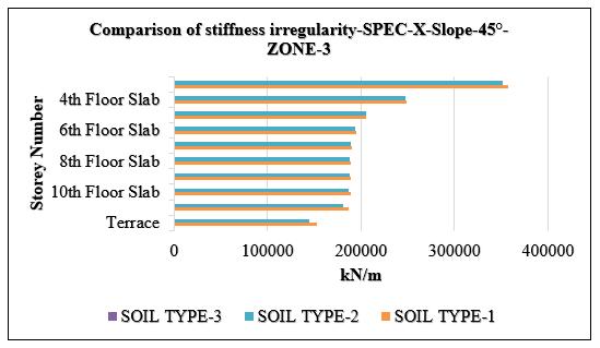
Figure 3.3.5. Comparison of stiffness irregularitySPEC-X-Slope-45°-Zone-3

Figure 3.3.6. Comparison of stiffness irregularitySPEC-X-Slope-45°-Zone-4

Figure 3.3.7. Comparison of stiffness irregularitySPEC-X-Slope-60°-Zone-3
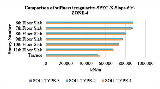
Figure 3.3.8. Comparison of stiffness irregularitySPEC-X-Slope-60°-Zone-4
3.4. STOREY STRENGTH

Figure 3.4.1. Comparison of storey strength-SPEC-XSlope-0°-Zone-3
2025, IRJET | Impact Factor value: 8.315 | ISO 9001:2008

International Research Journal of Engineering and Technology (IRJET) e-ISSN: 2395-0056

Figure 3.4.2. Comparison of storey strength-SPEC-XSlope-0°-Zone-4
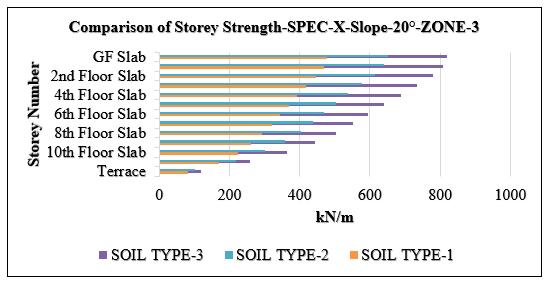
Figure 3.4.3. Comparison of storey strength-SPEC-XSlope-20°-Zone-3

Figure 3.4.4. Comparison of storey strength-SPEC-XSlope-20°-Zone-4

Figure 3.4.5. Comparison of storey strength-SPEC-XSlope-45°-Zone-3

Figure 3.4.6. Comparison of storey strength-SPEC-XSlope-45°-Zone-4
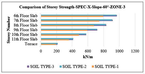
Figure 3.4.7. Comparison of storey strength-SPEC-XSlope-60°-Zone-3
Volume: 12 Issue: 05 | May 2025 www.irjet.net p-ISSN: 2395-0072 © 2025, IRJET | Impact Factor value: 8.315 | ISO 9001:2008 Certified Journal | Page

International Research Journal of Engineering and Technology (IRJET) e-ISSN: 2395-0056

Figure 3.4.8. Comparison of storey strength-SPEC-XSlope-60°-Zone-4
3.5. MASS IRREGULARITY

Figure 3.5.1. Comparison of mass irregularity-MASS-XSoil Type-1-Zone-3

Figure 3.5.2. Comparison of mass irregularity-MASS-XSoil Type-2-Zone-3

Figure 3.5.3. Comparison of mass irregularity-MASS-XSoil Type-3-Zone-3

Figure 3.5.4. Comparison of mass irregularity-MASS-XSoil Type-1-Zone-4

Figure 3.5.5. Comparison of mass irregularity-MASS-XSoil Type-2-Zone-4
Volume: 12 Issue: 05 | May 2025 www.irjet.net p-ISSN: 2395-0072 © 2025, IRJET | Impact Factor value: 8.315 | ISO 9001:2008 Certified

International Research Journal of Engineering and Technology (IRJET) e-ISSN: 2395-0056
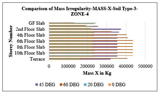
Figure 3.5.6. Comparison of mass irregularity-MASS-XSoil Type-3-Zone-4
3.6. FLEXIBLE & RIGID DIAPHRAGM

Figure 3.6.1. Comparison of flexible & rigid diaphragm-SPEC-X-Soil Type-1-Zone-3&4

Figure 3.6.2. Comparison of flexible & rigid diaphragm-SPEC-X-Soil Type-2-Zone-3&4

Figure 3.6.3. Comparison of flexible & rigid diaphragm-SPEC-X-Soil Type-3-Zone-3&4
Volume: 12 Issue: 05 | May 2025 www.irjet.net p-ISSN: 2395-0072 © 2025, IRJET | Impact Factor value: 8.315 | ISO 9001:2008 Certified Journal | Page1512

International Research Journal of Engineering and Technology (IRJET) e-ISSN: 2395-0056
Volume: 12 Issue: 05 | May 2025 www.irjet.net p-ISSN: 2395-0072
MODE SHAPE

Figure 3.7.1. Mode Shape-Slope-0°-Soil Type-1-Zone-3
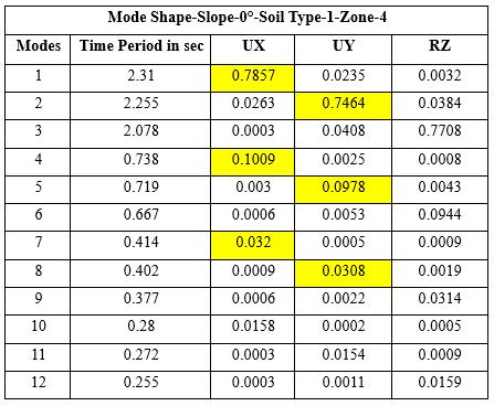
Figure 3.7.2. Mode Shape-Slope-0°-Soil Type-1-Zone-4

Figure 3.7.3. Mode Shape-Slope-0°-Soil Type-2-Zone-3

Figure 3.7.4. Mode Shape-Slope-0°-Soil Type-2-Zone-4

Figure 3.7.5. Mode Shape-Slope-0°-Soil Type-3-Zone-3
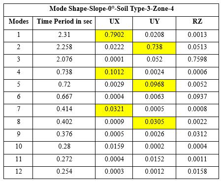
Figure 3.7.6. Mode Shape-Slope-0°-Soil Type-3-Zone-4
2025, IRJET | Impact Factor value: 8.315 | ISO 9001:2008

International Research Journal of Engineering and Technology (IRJET) e-ISSN: 2395-0056
Volume: 12 Issue: 05 | May 2025 www.irjet.net p-ISSN: 2395-0072

3.7.7. Mode Shape-Slope-20°-Soil Type-1-Zone3
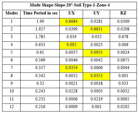
Figure 3.7.8. Mode Shape-Slope-20°-Soil Type-1-Zone4

Figure 3.7.9. Mode Shape-Slope-20°- Soil Type-2-Zone3
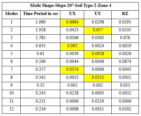
3.7.10. Mode Shape-Slope-20°-Soil Type-2Zone-4

Figure 3.7.11. Mode Shape-Slope-20°-Soil Type-3Zone-3

Figure 3.7.12. Mode Shape-Slope-20°-Soil Type-3Zone-4
2025, IRJET | Impact Factor value: 8.315 | ISO 9001:2008

International Research Journal of Engineering and Technology (IRJET) e-ISSN: 2395-0056
Volume: 12 Issue: 05 | May 2025 www.irjet.net p-ISSN: 2395-0072

3.7.13. Mode Shape-Slope-45°-Soil Type-1Zone-3

Figure 3.7.14 Mode Shape-Slope-45°-Soil Type-1Zone-4

Figure 3.7.15. Mode Shape-Slope-45°-Soil Type-2Zone-3

3.7.16. Mode Shape-Slope-45°-Soil Type-2Zone-4

Figure 3.7.17. Mode Shape-Slope-45°-Soil Type-3Zone-3

Figure 3.7.18. Mode Shape-Slope-45°-Soil Type-3Zone-4
2025, IRJET | Impact Factor value: 8.315 | ISO 9001:2008

International Research Journal of Engineering and Technology (IRJET) e-ISSN: 2395-0056
Volume: 12 Issue: 05 | May 2025 www.irjet.net p-ISSN: 2395-0072

3.7.19. Mode Shape-Slope-60°-Soil Type-1Zone-3

3.7.20. Mode Shape-Slope-60°-Soil Type-1Zone-4

Figure 3.7.21. Mode Shape-Slope-60°-Soil Type-2Zone-3
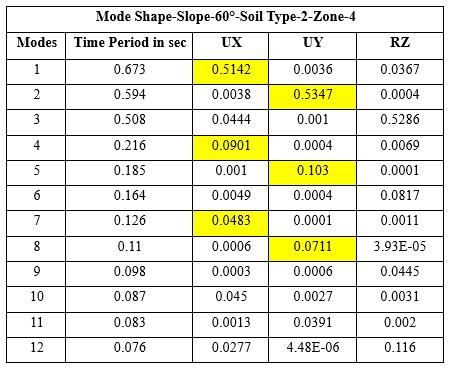
3.7.22. Mode Shape-Slope-60°-Soil Type-2Zone-4

Figure 3.7.23. Mode Shape-Slope-60°-Soil Type-3Zone-3
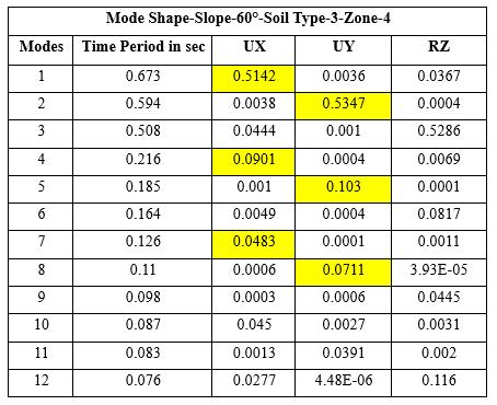
Figure 3.7.24. Mode Shape-Slope-60°-Soil Type-3Zone-4
2025, IRJET | Impact Factor value: 8.315 | ISO 9001:2008

International Research Journal of Engineering and Technology (IRJET) e-ISSN: 2395-0056
Volume: 12 Issue: 05 | May 2025 www.irjet.net p-ISSN: 2395-0072

Figure 3.8.1. Torsional Irregularity-Terrace LevelSPEC-X-Soil Type-1-Zone-3
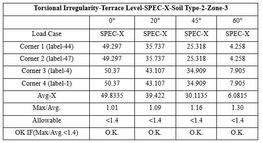
Figure 3.8.2. Torsional Irregularity-Terrace LevelSPEC-X-Soil Type-2-Zone-3

Figure 3.8.3. Torsional Irregularity-Terrace LevelSPEC-X-Soil Type-3-Zone-3

Figure 3.8.4. Torsional Irregularity-Terrace LevelSPEC-X-Soil Type-1-Zone-4

Figure 3.8.5. Torsional Irregularity-Terrace LevelSPEC-X-Soil Type-2-Zone-4
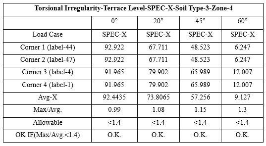
Figure 3.8.6. Torsional Irregularity-Terrace LevelSPEC-X-Soil Type-3-Zone-4
4. CONCLUSION
Theobservationsfromthisstudyclearlyshowthatterrain slope, soil type, and seismic zone intensity significantly affect the structural performance of buildings during seismicevents.Amongthesefactors,slopeangleprovedto be the most influential. This is mainly due to the vertical

International Research Journal of Engineering and Technology (IRJET) e-ISSN: 2395-0056
Volume: 12 Issue: 05 | May 2025 www.irjet.net p-ISSN: 2395-0072
irregularities caused by varying column heights and staggered floor levels, which disrupt the uniform distribution of stiffness and mass. Consequently, structures on steeper slopes are more vulnerable to stiffness irregularities, torsional effects, and uneven load paths, all of which greatly influence the building's overall seismicresponse.
1. Analysis of the data indicates that in Zone III, with Soil Type-1, the maximum lateral drift 0.001273. In contrast, at slopes of 45° and 60°, there was a significant reduction in drift, with values decreasing to 0.000104 and 0.000001, respectively.Thisphenomenoncanbeattributed to the changes in slope angle, which result in a vertical irregularity in the building's structure. Specifically, columns situated on the downhill side experience increased height, while those on the uphill side remain shorter, leading to a nonuniform distribution of stiffness throughout the structure. This distribution can cause the lower storeys to exhibit greater flexibility, thereby increasingsusceptibilitytodriftvariations.
2. In the present case, however, the drift values decreased with steeper slopes. To enhance structural performance, particularly under complex mode shapes observed in steep slope configurations, it is crucial to bolster the lateral stiffness of the structure. This can be effectively accomplished by increasing the dimensions of columnsandbeams,especiallyincriticalareason the 45° and 60° slopes where structural configuration is associated with high flexibility. By reinforcing these members, we can mitigate inter-storey drift and improve overall stability, ensuring a more balanced distribution of stiffnessthroughoutthebuilding'selevation.
3. Additionally, the change in soil type greatly influences storey drift under seismic loading; as soil transitions from hard (Type I) to soft (Type III),driftvaluesescalate.Forinstance,inZoneIII at0°slope,thedriftinSoilTypeIwas0.001273, which rose to 0.001779 in Soil Type II and 0.002186inSoilTypeIII.Softersoilsallowmore ground movement, leading to greater lateral displacement and increased risk of nonstructural damage and soft-storey failure. Similarlyithappensin20°,45°&60°.
4. The change in seismic zone significantly influences storey drift by increasing the seismic demandanddesignbaseshear.Asthezoneshifts from Zone III to Zone IV, higher lateral forces resultingreaterinter-storeydisplacements.At0° slope, the maximum drift for Soil Type-1
increased from 0.001273 to 0.001938, for Soil Type-2 from 0.001779 to 0.002638, and for Soil Type-3 from 0.002186 to 0.003234. A similar trend was observed at 20°, 45°, and 60° slopes, confirming that drift consistently rises with increasing seismic intensity, regardless of slope or soil condition. While the impact of zone change is less severe than that of soil or slope, it remainsacriticalfactorinseismicdesign.
5. The analysis shows that storey displacement decreases with increasing slope angle due to reduced building height and increased stiffness. For instance, in Zone III with Soil Type I, the maximum displacement at the terrace level was 36.043mmat0°slope,reducingto31.394mmat 20°, 24.664 mm at 45°, and 6.445 mm at 60°. Similarly, in Zone IV with Soil Type I, the maximum displacement at the terrace level was 54.91 mm at 0° slope, reducing to 46.835 mm at 20°, 36.875 mm at 45°, and 10.141 mm at 60° While higher seismic zones lead to greater displacement overall, steeper slopes consistently reducelateralmovement.
6. Soil condition also plays a crucial role, soft soils allowmorelateralmovement.At0°slopeinZone III, the terrace displacement increased from 36.043 mm (Soil I) to 50.37 mm (Soil II) and 62.028mm(SoilIII).Similarlyat0°slopeinZone IV, the terrace displacement increased from 54.91 mm (Soil I) to 74.828 mm (Soil II) and 92.922 mm (Soil III). Similarly it happens in 20°, 45°,and60°slopes.
7. Additionally, increasing the seismic zone from Zone III to IV resulted in higher displacements across all soiltypes.Forexample,in Soil TypeIII at0°slope,displacementrosefrom62.028mmin Zone III to 92.922 mm in Zone IV. Overall, the highest displacements were observed on flat terrainwithsoftsoilinZoneIV,whilethelowest occurred on steep slopes with hard soil in Zone III. This highlights the need for slope-adaptive structural design and soil-specific detailing to control lateral displacements under seismic loads.
8. The analysis reveals that stiffness irregularity is significantly influenced by slope angle, soil type, andseismiczone.Astheslopeincreases,stiffness at the terrace level increases due to shorter column heights on the uphill side and greater lateral restraint. In Zone III with Soil Type I, stiffnessrosefrom74,433.74kN/mat0°slopeto 80,538.24kN/mat20°,153,422.64kN/mat45°, andpeakedat547,569.85kN/mat60°.Asimilar

International Research Journal of Engineering and Technology (IRJET) e-ISSN: 2395-0056
Volume: 12 Issue: 05 | May 2025 www.irjet.net p-ISSN: 2395-0072
trend was observed in Zone IV. However, when soil type changes from hard to soft, stiffness decreases due to reduced ground support. At 0° slope in Zone III, terrace-level stiffness dropped from 74,433.74 kN/m (Soil Type I) to 69,147.99 kN/m (Soil Type II) and further to 66,288.21 kN/m (Soil Type III). Seismic zone variation had a minor effect on stiffness. For example, at 45° slopewithSoilTypeI,stiffnessincreasedslightly from 153,422.64 kN/m in Zone III to 153,486.11 kN/minZoneIV.Overall,steeperslopesenhance stiffness, while softer soils reduce it, and zone changes have minimal influence. These findings highlight the importance of maintaining a balanced stiffness profile to prevent soft-storey effectsandensureseismicstability.
9. The analysis indicates that storey strength increases with slope angle, primarily due to longer column heights and greater force demandsatthelowerstoreys.InSeismicZoneIII with Soil Type I, the storey strength increased progressively from 79.41 kN at a 0° slope to 82.41 kN at 20°, 180.42 kN at 45°, and reached a peak of 192.08 kN at a 60° slope. A similar pattern was observed in Zone IV. However, the influenceofsoiltypeshowedacontrastingtrend: softer soils generally resulted in higher storey strength at the upper levels, despite offering lower resistance overall. For example, at a 0° slope in Zone III, the terrace level strength rose from79.41 kNonSoilTypeIto100.55 kNonSoil TypeII,andfurtherto116.92 kNonSoilTypeIII. Additionally, seismic zone classification had a noticeable impact on stiffness.Ata 0° slopewith Soil Type I, stiffness increased from 79.41 kN in ZoneIIIto121.89 kNinZoneIV.
10. The analysis indicates that mass irregularity increasesnotablywithslopeangle,primarilydue to split-level configurations and the uneven distribution of structural mass across storeys. In Zone III with Soil Type I, the maximum mass at the 11th floor slab rose from 235,134.5 kg at 0° slope to 226,214.4 kg at 20°, then increased significantly to 355,273.7 kg at 45°, and peaked at 445,170.6 kg at 60°. This trend was similarly observed in Zone IV, confirming that steeper slopes contribute to greater mass concentration atupperlevels,therebyheighteningthepotential for mass irregularity. However, changes in soil type and seismic zone had minimal impact on mass distribution, with values remaining relatively consistent across different soil conditions and zones. These findings emphasize the importance of considering slope-induced mass irregularity in seismic design, as it can
influencetorsionalbehaviorandoveralldynamic response.
11. The analysis reveals that diaphragm flexibility increaseswithslopeangleand,particularlyatthe lower storeys. According to IS 1893:2016, a diaphragm is considered flexible if the in-plane deformationratioexceeds1.2.InSeismicZoneIII withSoilTypeI,thisratioatthegroundfloorslab increased from 1.061 at a 0° slope to 1.687 at 20°. Interestingly, at a 45° slope, the ratio decreased to 1.254 and further to 1.426 at 60°. This trend is attributed to the change in the startinglevel oftheregular floorslabsbeginning from the third floor at 45° and the sixth floor at 60° which resulted in higher flexibility ratios of 1.595 and 1.726, respectively, at those levels, thereby confirming flexible diaphragm behavior. A similar pattern was observed in Zone IV. Furthermore, diaphragm flexibility was found to decreaseslightlywithsoftersoils.Forinstance,at a 60° slope in Zone III, the flexibility ratio declined marginally from 1.061 (Soil Type I) to 1.056(SoilTypeIII).Acomparabledecreasewas noted with increasing seismic intensity; at a 60° slope with Soil Type I, the ratio reduced from 1.061inZoneIIIto1.056inZoneIV.
12. Modeshapeanalysis showsthatincreasingslope angle reduces the fundamental time period, indicating greater stiffness dropping from 2.31 s at 0° to 0.68 s at 60° slope. The first two modes were dominated by translational displacements (UX,UY),whiletorsionaleffects(RZ)appearedin higher modes, especially on steeper slopes. Soil type had minimal impact on mode shape patterns, though softer soils showed slightly higher displacements. Seismic zone changes had negligible effect on mode shapes. The first three modes contributed significantly to mass participation, meeting IS 1893:2016 requirements.
13. Torsional irregularity tends to increase with slope angle due to asymmetrical geometry and non-uniform lateral stiffness, which intensifies eccentric lateral displacements. In Zone III with Soil Type-1, the edge-to-center displacement ratio rose from 1.02 at 0° to 1.285 at 60° , indicating growing torsional effects at steeper inclinations. However, when the soil type changes from hard (Type-1) to soft (Type-3), torsional irregularity slightly decreases. For instance,at0°slope,theratioreducedfrom 1.02 (Soil Type-1) to 1.01 (Soil Type-3), suggesting that increased soil flexibility helps distribute seismic forces more uniformly, reducing

International Research Journal of Engineering and Technology (IRJET) e-ISSN: 2395-0056
Volume: 12 Issue: 05 | May 2025 www.irjet.net p-ISSN: 2395-0072
torsionalresponse.Despitevariations,allmodels remained within the IS 1893:2016 allowable limit of 1.4, confirming torsional stability under thestudiedconditions.
1. Birajdar, B. G., and S. S. Nalawade. "Seismic analysis of buildings resting on sloping ground." 13th world conference on earthquake engineering. No. 1472. 2004.
https://www.iitk.ac.in/nicee/wcee/article/13_1472 .pdf
2. Deep, V. Mani, and P. Polu Raju. "Pushover analysis of RC building: comparative study on seismic zones of India." Int. J. Civil Eng. Technol 8.4 (2017): 567578.
https://www.academia.edu/33287299/PUSHOVER_ ANALYSIS_OF_RC_BUILDING_COMPARATIVE_STUDY _ON_SEISMIC_ZONES_OF_INDIA?sm=b
3. Sanjay, Phatale Swarup, and S. R. Parekar. "Seismic analysis of Step-back building resting on sloping ground considering different types of Bracing system." International Journal for Modern Trends in ScienceandTechnology 5.07(2019).
https://www.academia.edu/40014417/Seismic_ana lysis_of_Step_back_building_resting_on_sloping_grou nd_considering_different_types_of_Bracing_system
4. Patel, Mohammed Umar Farooque, A. V. Kulkarni, andNayeemullaInamdar."APerformancestudyand seismic evaluation of RC frame buildings on sloping ground." IOSR Journal of Mechanical and Civil Engineering(IOSR-JMCE)e-ISSN (2014):2278-1684. https://www.researchgate.net/publication/323029
301_A_Performance_study_and_seismic_evaluation_ of_RC_frame_buildings_on_sloping_ground
5. Gaikwad, Apurva Arjun, and Atul B. Pujari. "Seismic analysis of low rise, Mid-rise and High-Rise RCC structureonslopingGround." InternationalResearch Journal of Engineering and Technology 6.7 (2019): 1357-1365.
https://www.researchgate.net/publication/323029
301_A_Performance_study_and_seismic_evaluation_ of_RC_frame_buildings_on_sloping_ground
6. Ghosh, Rahul, and Rama Debbarma. "Effect of slope angle variation on the structures resting on hilly region considering soil-structure interaction. “International Journal of Advanced Structural Engineering 11(2019):67-77. https://doi.org/10.1007/s40091-019-0219-3
7. Mohammad, Zaid, Abdul Baqi, and Mohammed Arif. "SeismicresponseofRCframed buildingsrestingon hill slopes." Procedia engineering 173 (2017): 17921799.
https://doi.org/10.1016/j.proeng.2016.12.221
8. Manjunath,P.,andYogeendraR.Holebsgilu."Seismic analysisofmultistoreybuildingwithflatslabresting on plain and sloping ground." Bonfring International Journal of Machine Interface, ISSN (2016): 22775064.
https://www.journal.bonfring.org/papers/mmi/vol ume4/BIJ-8150.pdf
9. Zaidi, Sahil Abbas, Tabassum Naqvi, and Syed MuhammadIbrahim."Studyontheeffectsofseismic soil-structure interaction of concrete buildings resting on hill slopes." Materials Today: Proceedings 43(2021):2250-2254. https://doi.org/10.1016/j.matpr.2020.12.532
10. Shabani, Mohammad Javad, and Ali Ghanbari. "Comparison of seismic behavior of steel building adjacent to slope topography by considering fixedbase, SSI and TSSI." Asian Journal of Civil Engineering 21.7(2020):1151-1169. https://doi.org/10.1007/s42107-020-00266-8
11. IS456(2000):PlainandReinforcedConcrete- Code ofPractice[CED2:CementandConcrete].
12. IS 1893: Part 1: 2016: Criteria for Earthquake Resistant Design of Structures - Part 1: General ProvisionsandBuildings.
13. IS 875 (Part 1) (1987, Reaffirmed 2008): Code of Practice for Design Loads (Other than Earthquake) For Buildings and Structures. Part 1: Dead Loads Unit Weights of Building Materials and Stored Materials(SecondRevision).UDC624.042:006.76.
14. IS 875 (Part 2) (1987, Reaffirmed 2008): Code of Practice for Design Loads (Other than Earthquake) For Buildingsand Structures. Part 2: ImposedLoads (SecondRevision).UDC624.042.3:006.76.
15. IS 875-3 (1987): Code of Practice for Design Loads (Other than Earthquake) for Buildings and Structures, Part 3: Wind Loads [CED 37: Structural Safety].
2025, IRJET | Impact Factor value: 8.315 | ISO 9001:2008