
International Research Journal of Engineering and Technology (IRJET) e-ISSN:2395-0056
Volume: 12 Issue: 04 | Apr 2025 www.irjet.net p-ISSN:2395-0072


International Research Journal of Engineering and Technology (IRJET) e-ISSN:2395-0056
Volume: 12 Issue: 04 | Apr 2025 www.irjet.net p-ISSN:2395-0072
Prakash Kumar Gupta-Madhur Srivastava
1M.Tech (CAD CAM) Scholar, Department of Mechanical Engineering, Ambalika Institute of Management & Technology, Lucknow, Uttar Pradesh, India
2 Assistant Professor, Department of Mechanical Engineering, Ambalika Institute of Management & Technology, Lucknow, Uttar Pradesh, India
Abstract- The modern manufacturing sector faces several obstacles in its quest to create goods with high strength, low production costs, and resistance to heat, corrosion, and fatigue. When compared to other manufacturingprocesseslikemachining,casting,etc.,the combinedextrusion-forgingmethodisusedtoovercome these issues by achieving enhanced material qualities, high production rates, and reduced material waste. The Combined Forging and Extrusion Process is a sophisticated method of metal formation in which the required result is obtained by forcing an initial billet throughdiepunchsetupsforbothextrusionandforging. The shape of dies, the percentage area reductions, and thefrictionalconditionsattheworkpiece/diecontactare thekey determinantsofthe metal flowpattern.Because of the complexity of the study and the sheer quantity of processelementsinvolved,generatingloadestimationin this process can be challenging. It is widely used in the aerospace and automotive sectors. The current study focuses on estimating the forming load required to employ this procedure to make the product, a collet chuck holder. Both computational and experimental studyhavebeendoneonthemetal flowpatternanddie cavity filling. For 3D modelling, Solidworks is the modelling programme of choice, while Deform3DTM is utilised for Simulation. Numerous experiments have beenconductedinordertocomparetheoutcomesofthe Simulation process. There is a strong correlation betweentheoutcomesoftheSimulationanalysisandthe experimental.
Keywords: FiniteElement Analysis(FEA),formingload, metal flow pattern, effective strain, Combined extrusion andforgingprocess,andextrusionforgingprocess.
In addition to their strength, availability, and other qualities, metals are important in modern technology becausetheyareeasilymouldedintousefulshapessuch assheets,rods,andtubes.
Three basic procedures may be used to make extensive useofmetalshapes:
By metal casting, which involves preparing and pouringmoltenmetalintoamould.
By use of plastic deformation process, which maintain the mass and quantity of metal, the metal moved and flowed plastically in different directions.
By machining procedures, which involve removing material to form it into the appropriateshape,orbyremovalofmetal.
Application of the Combining Extrusion and Forgingmethod to a collet chuck holding is a manufacturing method that combines two different processesintoonehigh-qualityproduct.
A billet of material is driven through a die during the extrusion process to create a continuous profile with a consistent cross-section. This technique is often used to producetubularorcylindrical objectswithgoodsurface polishandregularproportions.
In contrast, The process of forging metal involves applying high compressive forces. Usually, the material is heated to increase its malleability before being pressedorhammeredintotherequiredform.Byaligning the grain structure and enhancing the material's strength and toughness, forging may improve its mechanicalqualities.
Manufacturers may achieve higher mechanical qualities, dimensionalprecision,andsurfacepolishincolletchuck holders by combining the benefits of forging and extrusion. This hybrid technique ensures the durability needed for demanding applications and enables the economical manufacturing of complicated forms with tighttolerances.
Anumberofprocedureshavedevelopedforspecificuses inmetalworking.Theseprocedurescanbedividedintoa few groups according to the kinds of forces that are applied to the workpiece. The following are these categories:
Compared to casting and machining, deformation methods yield metal geometries with superior mechanical qualities. Advanced metal forming usually involves casting the metal into a shape that is almost identical to the final product, then further deforming it

International Research Journal of Engineering and Technology (IRJET) e-ISSN:2395-0056
Volume: 12 Issue: 04 | Apr 2025 www.irjet.net p-ISSN:2395-0072
into the desired shape. In this approach, the number of stages in the deformation process may be minimised, leadingtomoreconsistentmetaldeformation.
The impact of process factors like friction factor and geometricalcharacteristicslikegapheightandfiecorner radiiwasexaminedbyFarhoumandetal. Hecametothe conclusion that When the height of gap or die corner radius increase, the materials flows radially. Furthermore,heconcludedthatvariationsinthefriction factor have an impact on the materials are flow into the fast forward and backward parts, even and if the materials are flow into the radial component is essentiallytoindependentofthefrictionfactor.
Plancak and colleagues looked at the radial extrusion of gears-likeparts.Wenoticedthattheloadrisessharplyin the final stage of the load stroke diagram. Additionally, he noted that the highest and lowest strain values had beenfound,respectively,attheteethandcentreportions ofthebillet.
The analysis of gear-like component lateral extrusion was done by Jafarzadeh et al. [9]. He noticed that while friction factor has some effect on the forming load, gap height has a greater effect. He came to the conclusion that the effective Strain increased with an increase in frictions coefficient and became heterogeneous with a decrease in billet diameter. Additionally, when the billet height increases and the frictions coefficient falls, the degreeofbarrellingreducesaswell.
The analysis of the cold-die extrusion/forging process was done by Brayden et al. He discovered that the neutral radius, which occupies a point to achieve the least energy dissipation state, is the important component in the study. Additionally, the neutral radius'sbehaviourisinfluencedbythestartingpressure and the abrupt increase in pressure that occurs throughout the extrusion process as a result of internal shear.
Thesimulationfindingsshowthattheproposedtestcan evaluate friction both qualitatively and quantitatively, accordingtoBuschausenetal.Healsofoundthatthetest conditions, which exhibit a high interface pressure and substantial deformation, are similar to those seen in industrialmanufacture.
The finite element method was used by Hu et al. to characterise the deformation of a rectangular billet. He discoveredthatthenumericalresultsagreewellwiththe experimentaldataintermsofdeformed geometry.
Wuetal.usedthefiniteelementapproachtoinvestigate the effects of different die shapes on extrusion forging.
He discovered that the extrusion loads, strain, and flow deformation were all influenced differently by the draft angleandfilletradius.
AccordingtoVickeryetal. thesizeofthedieholeaffects how the material behaves within the workpiece. The material with the bigger die hole would fill and transitionfirst.
An experimental study on barreling aluminium alloy billets during extrusion-forging using various lubricants was conducted by Narayan Swamy et al. He came to the conclusion that under both planar and triaxial conditions, all stress levels rise with approach angles. The relationship between the axial strain and the hoop strain is shown by a straight line. The approach angle affects the barrelling radius, which changes with hydrostaticload.
Afterobservingthelateralextrusionofhexagonalheads, Paltasingh et al. came to the conclusion that the thickness and cross sectional area of the die cavity increased the formation stress. It was also noted that as the corners of the die cavity are filled, the load rises suddenly.
An experimental study on upper limit analysis of the torsional backward extrusionprocess wasconducted by Kim et al. Using the stream function, he produced a velocities field that was kinematically acceptable. Compared to traditional backward extrusion, thirty percentlessdeformationforcewasrequired.
Finite element analysis or FEA is a potent numerical technique for simulating the behaviour of intricate engineeringsystemsandstructuresisfinite.Itisusedin many different sectors, including as biomechanics, civil engineering, automotive, aerospace, and more, to forecast how a system or component will react to particularoperatingsituations.
Fundamentally, Finiteelementanalysis (FEA)dividesan intricate structure into smaller, more manageable components, or meshes, linked at certain locations known as nodes. These elements behave according to mathematical formulae, which are frequently based on physicsconceptslikeequilibriumandconservationlaws. FEA determines how the entire structure will react to applied loads, boundary conditions, and material attributesbyrepeatedlysolvingtheseequations.
Performing FEA usually entails the following steps:
i. Pre-processing: This entails utilising specialised software to create a geometric model of the structure. After that, the model is divided into

International Research Journal of Engineering and Technology (IRJET) e-ISSN:2395-0056
Volume: 12 Issue: 04 | Apr 2025 www.irjet.net p-ISSN:2395-0072
discrete parts, and loads, boundary conditions, and materialattributesarespecified.
ii. Meshing: For 2D analysis, the structure is split up into triangles or quadrilaterals, and for 3D analysis, it is split up into tetrahedra or hexahedra. The analysis's accuracy is influenced by the mesh density; finer meshes yield more accurate findings butdemandmoreprocessingpower.
iii. Applying Loads and Boundary Conditions: In order to mimic how the structure interacts with its environment, boundary conditions such as fixed limits or prescribed displacements are applied. To further imitate real-world working circumstances, external loads are introduced, such as forces, pressures,ortemperaturegradients.
iv. Solving: Using iterative techniques like the boundary element or finite element methods, the systemofequationsregulatingthebehaviourofeach element is numerically solved. The displacement, stress, and strain distributions inside the structure arecomputedinthisstage.
v. Post-processing: At this point, the analysis's findingsarepresentedandexplained.Engineersmay assess the performance of the structure and make wise design choices by looking at a variety of outputs, such as deformation plots, stress contours, safetyfactors,andresonancefrequencies.
Numerous experiments have been conducted for the currentanalysisinordertocomparetheoutcomesofthe finite element Simulation with the experimental results. Initially,asetupwascreatedandbuilttouseacombined extrusion-forging technique to create Collet Chuck holders. Several tests have been conducted on a 600kN maximum capacity Universal Testing machine with cylindrical aluminium specimens to obtain the ColletChuck holder that is the end result. Additionally, ring and compression tests have been performed to ascertainthefrictionfactorsandstress-strainproperties, respectively.
The experimental setup consists of the base plate, and punchhead,sleeve,punchrod,forging-extrusiondieand die holders. It has been addressed which components were employed in the experimental setup. The EN31 steel container measures 140 mm in diameter and 100 mm in length. Its cylindrical chamber measures 50 mm in diameter and 100 mm in length. It may be done by rotating the container's outside diameter and utilising wire cut EDM to drill the interior chamber with a
tolerance of ±.02 mm. During testing, the rear of the sleeve that has been inserted within the container chamberispreventedbyusingthecoverplate.Insidethe container chamber is the container sleeve, whose inner and outer diameters should coincide with the diameter of the main punch and the container chamber, respectively. The purpose of the container sleeve is to prevent the punch rod from expanding by guiding it throughthecontainer.Dieholders-1and-2,whichwere producedutilisingcomparable procedures. D2steel was used in the manufacturing of the punch rod, circular punch head, circular split dies, and circular taper split die. Push fit alignment is used to join the punch rod-2 and the punch head. Using EN 8 steel, the foundation platewascreated.
Experiments were carried out on a 600kN maximum capacity Universal Testing Machine using cylindrical aluminium billet. Once all the parts of the experimental setuphavebeenwellcleaned,lubricant(oil,forexample) has to be applied to the inside surfaces of the dies, as wellastheholders,punch,andsleeves.Furthermore,the punchispositionedabovethebilletofaluminium,which is then lubricated and placed within the die cavity. Now the container is placed on the die holder and bolted in place. The main punch is finally placed within the containersleeve,whichisthenplacedintothecontainer chamber.Aftereverythingissetup,the600kNmaximum capacity universal testing machine's bottom table is where it is placed (Fig. 4.1). Now turn the machine on andfine-tuneitsparameters,suchasthemaximumload, anvil height, billet diameter, strain rate, and punch movement length. The dimensions of the anvil height, billet diameter, punch movement length, and punch speedin thisresearchprojectare54 mm,15mm,and 1 mm/min, respectively. When the punch action reaches the prescribed length of 24.6 mm, the machine stops. A punchloadisrecordedforeverythirtysecondsofpunch movement. After the experiment was over, the die sets containing the final result were removed using a progressive load, and the punch die arrangement was dismantled.ThefinalresultoftheCombinedForgingand ExtrusionProcessisaColletChuckholder,whichwasthe expected outcome. Various punch movement lengths have been used in experiments to look at die cavity fillingandmetalpatternofflows.

International Research Journal of Engineering and Technology (IRJET) e-ISSN:2395-0056
Volume: 12 Issue: 04 | Apr 2025 www.irjet.net p-ISSN:2395-0072
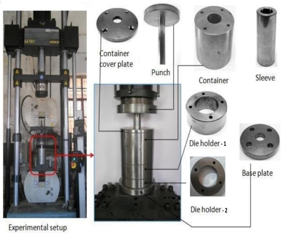
photoshowsthekeycomponentsofthe experimentalsetup
The flow stress was calculated using a power equation derived from the stress-strain curve, and the cylindrical aluminium billet's stress-strain characteristics were determinedbythecompressiontest.First,thecylindrical aluminium billet, which had dimensions of 18 mm in diameter and 32 mm in length, was machined from casted billet material. To help hold on to the lubricant, several oil grooves have developed on the specimen's top and bottom surfaces. The bottom table of the UTM hasbeenadequatelylubricatedandcoveredwithgrease or another lubricant. The uniaxial compression test was performed by gradually increasing pressure, and the compressive force was measured at each 0.2 mm of punchmovement.Themachinehaltedoncethe2mmof compression was finished, and the compressed billet was remachined in accordance with the original billet specifications. The procedure has been carried out until the height reaches 25.25 mm. Ultimately, Fig. 4.3 displaystheplottedstress-straincurve.
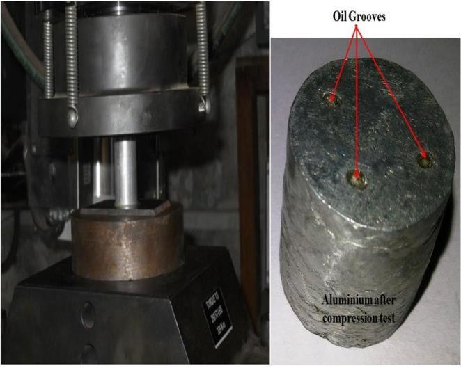
specimensetupforcompression testing
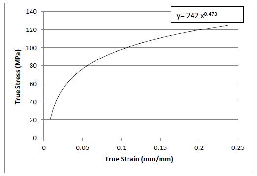
Fig..4.3:Thetypicalcurveofstress-strainforaluminium
According to Fig. 4.3, we are able to ascertain a suitable power equation curve, which is represented in equation (1):

The strain hardening index is 0.473 and the strength coefficient is 242 MPa when we compare equation (1) withHolloman'sequationofpower.Thepowerequation was utilised in the Simulation procedure, and the flow stressof125MPawasdeterminedfromthestress-strain curve.
The fundamental determinant of the forming load, flow of metal pattern, and internalgrain structure is the frictional condition at the billet/die contact. A flat ring

International Research Journal of Engineering and Technology (IRJET) e-ISSN:2395-0056
Volume: 12 Issue: 04 | Apr 2025 www.irjet.net
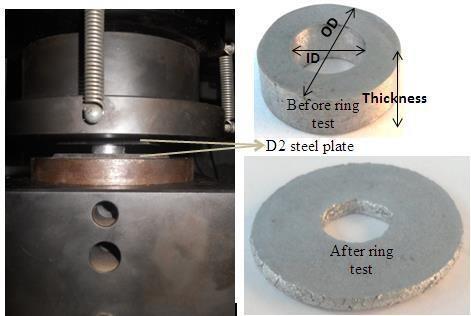
specimenplastically compressed within two flat platens reveals insufficient lubrication when there is more friction, which causes the metal to flow inward; less friction indicates enough lubrication, which causes the metal to flow outward. Accordingly, in a compression test, a greater internal diameter indicates less friction, whereas a smaller internal diameter indicates more friction. Fig. 4.4 illustrates how the specimen changes formwhencrushedbothwithandwithoutlubrication.
The ring compression test has been conducted in this study both with and without lubrication. A flat ringshaped specimen with an OD: ID: H ratio of 6:3:2 has been taken into consideration for this ring compression test. The ratio indicates that the ring's dimensions are 18:9:6, and a ring test has been conducted. Two flat die plateswiththeidenticalinteriorsurfaceconditionswere compressed in order to provide an accurate assessment of the friction between the die/billet interfaces. Following the ring test, a curve was created using the recorded values. The ring test curve and the friction factor determination were compared using standard calibration curves. In the ring test, the friction factor achieved with lubrication is 0.22, and without lubrication,itis0.28.

ringtest
p-ISSN:2395-0072
4.4.1. Different phases of the Combined Forging and Extrusion Process's product production
OnaUniversaltestingmachine(UTM),experimentshave been conducted to create the necessary product, a ColletChuck holder, utilising a combined extrusionforging method. It has been noted that there are four steps in the entire compression process. The billet's initial compression is visible in the first step. The taper die's forging and a little indentation hole have been finished in the second step. The third stage sees the completion of both forging and extrusion. At this point, the last circular extrusion component is finished. The product hadreached the fourthstep, whenflasharrived and the finishing was finished. The graphs showing the change of punch load with punch movement at various punchmovementareshowninFig.s4.6to4.8.
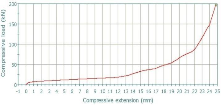
Figure.4.6:Punchloadvariationwithstrokefora24.8 mmpunchmovementlength
InTheFig4.6 ,Thepunchloadvariationwithrespectto punch movement at 24.8 mm of punch movement is represented by 4.6. This is the whole product that was produced using Flash. 191.22 kN of load is needed for theproducttofullyform.
InTheFig. 4.7, Thepunchloadvariationwithregardto punch movement for a 24 mm punch trip length is shown by fig 4.7. In comparison to the 24.8 mm punch movement, there is not much variance. Here, the full product is acquired, and the flash has just begun to appear. 139.76 kN of load is needed at 24 mm of punch movement. The load for punch movement of 24.8 mm and 24 mm varies significantly. This is because the extrusionsectionisstillunfinishedandtheflashhasnot yet developed at 24 mm of punch movement. Thus, compared to 24 mm punch movement, 24.8 mm punch movementrequireshigherweight.

International Research Journal of Engineering and Technology (IRJET) e-ISSN:2395-0056
Volume: 12 Issue: 04 | Apr 2025 www.irjet.net p-ISSN:2395-0072
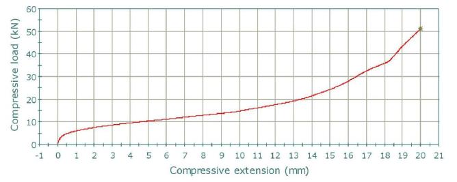
Figure4.7:Punchloadvariationwithstrokefora20mm punchmovementlength
Fig. 4.8 displays the punch variation in load in relation topunchmotionforapunchtriplengthof20mm.Atthis point, only the partial development of the tapered componentandtheentiremanufactureoftheholeinthe first segment have been achieved. The circular flash component and the extrusion part are not yet operational. The required forming load at 20 mm of punchmotionis51.08kN.
The punch load variation with regard to punch movementfora15mmpunchtriplengthisshowninFig. 4.8. This phase just signifies the preliminary compression. The billetis piercedby the punchhead.At 15mmofpunchmotion,aloadof22.72kNisneeded.
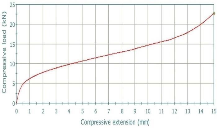
Figure4.8:Punchloadvariationwithstrokefora15mm punchmovementlength
5. CONCLUSIONS
In the current study, a combined extrusion forging method has been used to create ColletChuck holders through Simulation and experimental analysis. The outcomes of the experiment and the Simulation accord rather well. Based on the acquired outcomes, we may makeafewdeductions.
A ColletChuck holder was constructed by simulating the Combined Extrusion and Forgingprocess using a finite element method and the DEFORM 3D application. Analysis has been doneonanumberofcharacteristics,includingtotal
velocities,CombinedExtrusionandForgingprocess, effectiveStrain,andmetalpatternofflows.
Various length punch movement (length of punch movement) has been investigated through experimentation and Simulation, revealing the severalphasesinvolvedinmetalfilingindies.
Anexperimental arrangementhasbeencreatedfor the ColletChuck holder's combined extrusionforgingoperation.
Aluminiumflowstresswascomputedandfoundto be 125 MPa, while a universal testing machine's ringtestyieldedafrictionfactorvalueof0.22.
The Simulation technique and the punch load variation in relation to the displacement curves obtainedfromtheexperimentcorrespondwell.
The results of the models agree well with the experimental die filling, metal pattern of flow, and loadrequirements.
The current study may be expanded to investigate additional facets of the Combined Extrusion and Forgingprocess. Some recommendations for further workareincludedbelow.
This technique was expanded to work with differentmaterialsinhotenvironments.
Verification of the experimental analysis results canbeachievedusingupperboundanalysis.
Diestressescanbedeterminedbyextendingthe use of the suggested Finite element analysis (FEA)
This technique may be expanded upon to provide analysis for other materials and intricateforms.
[1] Manufacturing Engineering and Technology, 5th ed., Kalpakjian S, Schmid R. Pearson Education,theyear2006.
[2] MaterialSelectionandProcessing,LovattAM, Shercliff H R, and Withers P J, London: TechnologyEnhancementProgramme,2000.
[3] Hand Book of Metal Forming, Lange K. First edition. Society of Manufacturing Engineers, Michigan,1985.

International Research Journal of Engineering and Technology (IRJET) e-ISSN:2395-0056
Volume: 12 Issue: 04 | Apr 2025 www.irjet.net p-ISSN:2395-0072
[4] 10thed.ofTheMaking,Shaping,andTreating ofSteebyLankfordWT,SamwaysNL,Craven R F, and McGannon H E. United States Steel Co.,Pittsburgh,1985.
[5] Dieter, G. E. Metallurgy mécanique. third edition.McGraw-Hill,London,1988.
[6] Sheet Metal Forming Processes and Applications, Altan T, Tekkaya A E, ASM International,UnitedStatesofAmerica,2012.
[7] Analysis of the forward-backward-radial extrusion process by Farhoumand A and Ebrahmi R. Materials and design, 30 (2009), pp.2152-2157.
[8] Tehnicki vjesnik, 20: 5 (2013): pp. 891-896; Plancak M, Rosochowska M, Skakun P. Radial extrusionofgear-likecomponents-Numerical andexperiment.
[9] Journal ofmechanical scienceandtechnology, 2012; Jafarzadeh H, Faraji G, Dizaji A F. Analysisoflateralextrusionofgear-likeshape pieces,pp.3243-3252.
[10] An examination of closed-die extrusion/forging was conducted by Brayden L. and Monaghan J. in the Journal of Material Processing Technology, 26 (1991), pp. 141–157.
[11] Evaluation of lubrication and friction in cold forging using a twofold backward-extrusion method by Buschausen A, Weinmann K, Lee J Y, and Altan T. Journal of material processing technology,31(1992):pp.95-108.
[12] In the Journal of Material Processing Technology, Hu W, Hashmi M S J, and Liu P. "Study of metal flow in extrusion forging of rectangularbillets,"43(1994),pp.51–59.
[13] The impact of die shape on extrusion forging flow deformation was examined by Wu C. Y. and Hsu Y C. in the Journal of Material Processing Technology, Volume 124, Issue 2, 2002,pages67–76.
[14] An examination of a forging/extrusion process's first phases was conducted by Vickery and Monghan in the Journal of Material Processing Technology, 43 (1994), pp.37–50.
[15] An experimental examination on barrelling of aluminium alloy billets during extrusion forging using different lubricants was
conducted by Narayan Swamy R, Baskaran K, Arunachalam S, and Muralikrishna D. Journal of Materials and Design, 29 (2005): pp. 20762088.
[16] FEM analysis and experimental examination for lateral extrusion of hexagonal head, Paltasingh U C, Sahoo S K, Nayak K C, International Journal of Engineering Research andApplications,3:4(2013),pp.1265-1271.
[17] The investigation of the cup rod combination extrusion forging process of magnesium alloy (AZ61A)wasconductedbyYaminH,ZhouyiL, andYuchungZ.ItwaspublishedintheJournal of Material Processing Technology, 187-189 (2007),pp.649–652.