
International Research Journal of Engineering and Technology (IRJET) e-ISSN: 2395-0056
Volume: 12 Issue: 05 | May 2025 www.irjet.net p-ISSN: 2395-0072
Manufacturing of a cost-effective
3D Printer for prototyping and educational purpose.
Kaivalya
Kulkarni1 , Samarth Joshi 2 , Akash Jadhav 3 , Suraj Bodake 4 , Aashish Mali 5 , Prof. P. L Firake6
#Dept. of Mechanical Engineering , JSPM's Rajarshi Shahu College of Engineering, Tathawade, Pune, Maharashtra
Abstract - Additive manufacturing (AM), especially Fused Deposition Modelling (FDM), has become increasingly popular due to its affordability and flexibility. This project aims to design and assemble a custom FDM 3D printer, allowing us to gain practical experience in additive manufacturing while providing a functional printing solution for our institution. The printer is constructed using an Arduino Mega 2560, RAMPS 1.4, NEMA 17 stepper motors, and a Creality Ender 3 V2 hotend. During our initial test prints, we encountered problems like layer misalignment and unstable vertical movement. To find solutions, we researched and found a reference video that demonstrated the addition of structural supports Lsupports and R- supports to stabilize the lead screw and minimize vibrations. Motivated by this, we decided to implement similar modifications by 3D printing custom supports on an Ender 5 Pro. We anticipate that these changes will enhance print accuracy, improve dimensional stability, and decrease mechanical inconsistencies. This paper outlines the design, assembly, challenges, and modifications made to our 3D printer. We will conduct final print tests to confirm the improvements, making this project a valuable resource for students and researchers interested in the development of 3D printer
Key Words: Fused Deposition Modelling, Additive Manufacturing, 3D Printer Development, Lead Screw Stability, RAMPS 14, Arduino Mega 2560, Print Quality Optimization
1.INTRODUCTION
Additive Manufacturing (AM), commonly known as 3D printing, has revolutionized the way objects are designed andfabricated.TheconceptofAMdatesbacktothe1980s, with the development of stereolithography (SLA) by CharlesHullin1986,whichlaidthefoundationformodern 3Dprinting.Overtheyears,variousAMtechniquessuchas SelectiveLaserSintering(SLS),FusedDepositionModelling (FDM), and Digital Light Processing (DLP) have been developed, each catering to different industrial and consumer needs. Among these, FDM technology, introduced in the late 1980s and patented by Stratasys in 1992, has become the most widely used due to its affordability,easeofoperation,andmaterialversatility.
This project focuses on the design and fabrication of a cost-effectiveFDM3Dprintertogainhands-onexperience in additive manufacturing and provide a functional printing solution for our institution. The motivation behind this project stems from the lack of a working 3D printer in our college, which limits students’ ability to explore and experiment with 3D printing technology. To bridge this gap, we aimed to build a 3D printer from scratch,understandingitsmechanicalstructure,electronic control systems, and software configurations. Through this,wesoughtto developa deeperknowledgeofstepper motor control, firmware tuning, calibration, and material extrusionprocesses.
The 3D printer was developed using Arduino Mega 2560 with RAMPS 1.4, NEMA 17 stepper motors, A4988 motor drivers, a V6 J-head hot end, and a MK2B heated bed, ensuring a balance between affordability and functionality. During initial tests, print quality issues such as layer misalignment and unstable vertical movement were observed. After researching potential solutions, we found that lead screw vibrations contributed to these errors. Inspired by a reference study, we integrated LsupportandR-supportstructuralmodificationstostabilize the lead screws and improve print accuracy. These supports were 3D-printed using an Ender 5 Pro and are currently being integrated into our system.
This paper documents the design, fabrication, assembly, and testing of our custom 3D printer, highlighting the challenges faced, modifications made, and expected improvements.

International Research Journal of Engineering and Technology (IRJET) e-ISSN: 2395-0056
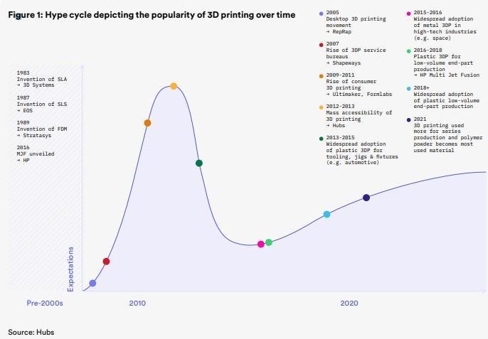
Figure1.Hypecycledepictingthepopularityof3Dprintingovertime(Source:Hubs)
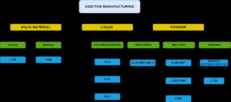
Figure2.Typesofadditivemanufacturingprocesses(madewithdraw.io)
Volume: 12 Issue: 05 | May 2025 www.irjet.net p-ISSN: 2395-0072 © 2025, IRJET | Impact Factor value: 8.315 | ISO 9001:2008 Certified Journal | Page1736

International Research Journal of Engineering and Technology (IRJET) e-ISSN: 2395-0056
Volume: 12 Issue: 05 | May 2025 www.irjet.net p-ISSN: 2395-0072
1.1. ADDITIVE MANUFACTURING
According to the paper by Tomasz Grzegorz Gaweł, titled "Review of Additive Manufacturing Methods," additive manufacturing (AM) has progressed significantly from rapid proto- typing to large-scale production. It now provides a variety of techniques for creating parts from polymers,metals,ceramics,andcomposites.
The Additive Manufacturing processes can be separated according to input material and type of process carried out.Inputmaterialscanbesolid,liquid,powder[1].
Additive Manufacturing (AM), or 3D printing, is a layerby-layer creation of objects from a digital 3D model. It begins in Computer-Aided Design (CAD) software, where the object is designed and then converted into a stereolithography(STL)fileoranotherusableformat.The file is processed using slicing software, which divides the model into thin layers and creates instructions (G-code) for the 3D printer. Once the file is prepared, the printing process begins, using either a bottom-to-top or top-tobottom layer-depositing method, depending on the AM technologyemployed.
In Selective Laser Sintering (SLS) and Fused Deposition Modelling(FDM),materialisdepositedormeltedlayerby layer from the bottom up. A hot nozzle deposits thermoplasticsinFDM,whileinSLS,alasermeltspowder particles. Stereolithography (SLA) and Digital Light Processing(DLP)workintheoppositedirection,fromthe top down, using a UV laser or light to cure liquid resin as the object builds upwards. Binder Jetting and Material Jettingdepositmaterialorbindingagentslayerbylayeron asurface,typicallyfromthebottomup.Thispreciselayerby-layer building enables complex forms, minimal material waste, and highly customized designs, making AdditiveManufacturingasignificanttechnologyinmodern manufacturing.
1.2. PROBLEM STATEMENT
Accesstoaffordable3Dprintersineducationalinstitutions is limited, restricting hands-on learning in additive manufac-turing.Toaddressthis,weaimedtobuildacosteffective 3D printer for our college lab while gaining practical knowledge of 3D printing technology. This project enhances learning opportunities and provides an affordableprototypingsolutionforstudents.
1.3. OBJECTIVES
Develop and produce a low-cost 3D printing device that can be utilized for prototyping and educationalpurposes.

Gain hands-on experience in additive manufacturing by understanding the operational processes, hardware integration, and firmware setupinvolvedwitha3Dprinter.
To design a modular FDM 3D printer with opensourcecomponentsandfirmwaretoenablefuture customization.
Toincreaseknowledgeonmodellinganddifferent parameters of firmware configurations (for e.g., JERK,Stepspermmandetc.)
1.4. SCOPE
Theprojectisallaboutdesigning,developing,and fine- tuning a budget-friendly FDM 3D printer with a build volume of 200mm x 200mm x 200mm.The main aim here is to create an affordableandaccessibleprototypingsolutionfor educational institutions, especially for students and re- searchers diving into engineering and manufacturing. Unlike those pricey commercial 3D printers, this initiative focuses on using costeffective components while still ensuring that the printerisreliableandproducesaccurateprints.
By tackling these key areas, the project hopes to achievethefollowing:
Cost-Effective Design – Create a low-cost 3D printer using open-source firmware (Marlin) and commonly available parts (like RAMPS 1.4 and ArduinoMega2560).
Educational Utility – Give students hands-on experience with additive manufacturing, helping them grasp 3D printing technology, firmware setup,andmachinecalibration.
Print Quality Optimization – Make structural enhancements such as lead screw supports and optimized stepper motor calibration to boost printaccuracyandconsistency.
Customization and Upgradability – Design the printertobemodular,soitcanbeeasilyupgraded in the future with features like automatic bed levelling, advanced stepper drivers (like TMC2208),andmulti-materialextrusion.
PracticalImplementation–Buildafullyfunctional prototype that can be used in the college lab, allowing students and faculty to explore rapid prototyping, research projects, and hands-on manufacturingexercises.
1.5. METHODOLOGY
A. IDEATION PHASE
i. Project Topic Discussion and Finalization: Discussed with group members and faculty guides to finalize a final- year project having practical use and innovation possibilities. Finalization of the idea to build a low-cost 3D printer was finalized keeping in view educationalutilityandexistingmarketneeds.

International Research Journal of Engineering and Technology (IRJET) e-ISSN: 2395-0056
Volume: 12 Issue: 05 | May 2025 www.irjet.net p-ISSN: 2395-0072
ii. Early-stage Research: Carried out initial research across different types of 3D printers, such as FDM (Fused Deposition Modelling) technology, trending open-source hardware platforms (e.g., Arduino Mega 2560 with RAMPS 1.4), and standard components appropriateforlow-costmanufacture.
B. FINALIZATION STAGE
i. Problem Statement Development: Composed a brief problem statement highlighting the lack of affordable 3D printers in schools and the need foraDIYapproach.
ii. In-DepthResearch: Conducted thorough analysis of open-source designs, firmware (specifically Marlin), andslicingsoftware(such as UltimakerCura and Repetier- Host), and determined settings appropriate for our own customized printerconfiguration.
C. LITERATURE SURVEY
i. Component Selection and Functionality Analysis: Study technical documents and online forums to understand the working principles of key components like NEMA 17 motors, A4988 stepper drivers, MK2B heated beds, and V6 hot ends
ii. Benchmarking and Feasibility Analysis: Compared similar low-cost printer designs to establish a baseline for print volume, resolution, andoverallperformance.
D. DESIGN AND ASSEMBLY PHASE
i. CADModellingandFrameDesign:Designeda3D printermodel using Catia. Developed frame with aluminium profiles and mild steel components forcostandstructuralintegrity.
ii. Electronics and Wiring Layout: Planned and implemented the wiring diagram for the RAMPS 1.4 board, Arduino Mega 2560, end stops, thermistors,andpowersupply.
iii. Firmware Configuration: Printer-specific Marlin firmware based on printer parameters like steps/mm, thermistor model, bed size, and ends toplogic.
E. CALIBRATION AND TESTING
i. Axis Calibration: X, Y, and Z axes calibrated to precise steps/mm using threaded rods and pulleys.
ii. First Print Trials: Conducted first test prints using PLA+ to test adhesion, layer uniformity, andextrusion.
iii. Troubleshooting: Solved problems like X-axis drift, extrusion gaps, and motor calibration by updatingfirmwareandhardwarechanges.
F. EVALUATION AND MODIFICATIONS
i. Print Quality Test: Sample prints tested for precision of dimensions, overhangs, and surface finish.
ii. ThermalManagementandSafetyCheck:Checked hot end and bed heat profiles for safe temperaturesandelectricalsafety.
iii. Iteration and Upgrades: Improved tensioners, improved cable management, and researched further upgrades (like silent stepper drivers or improvedbedlevelling)forextendeduse.
2. LITERATURE REVIEW
A. TomaszGrzegorz Gaweł [1] The manuscript reviews theadditivemanufacturingtechnology.Theprinciple of operation of the most popular and new AM methodswasdiscussed.themanuscriptpresentsthe possibility of skewing different materials for individual technologies. Additive manufacturing technologies have been described that can manufacture parts from polymers, metals, ceramics andcomposites.
B. 3D Printing Failures (2020 Edition) by Sean Aranda [2] was referred to for troubleshooting and setting printing parameters. Based on the book’s recommendations, a hot end temperature of 200◦C and a bed temperature of 60◦C were used for PLA, improving first-layer adhesion and overall print quality.
C. The project report “3D Printer Using Fused Deposition Modelling” [3] by D. Supriya, K. Jayanth, K.H.V.S Sai Madhu, and Ch. Sai Krishna details the development of an affordable FDM 3D printer using Arduino Mega 2560 and PLA material. It covers programming with Arduino IDE, slicer software for G-code generation and successful prototype printing.
D. Theguide"Wiring3DPrinterRAMPS1.4:12Stepsby Core3D)" [4] discusses the complete wiring process of a RAMPS 1.4-based 3D printer, covering connections for mo- tors, endstops, heaters, thermistors, and power supply. We referred to this guidetocorrectlywirealltheelectroniccomponents of our 3D printer, ensuring safe and functional operation.
E. TheDocument“ConfiguringMarlin-Marlin3Dprinter firmware” [5] discusses the customization of Marlin firmware settings for different 3D printer hardware. We referred to it for configuring firmware parameters such as thermistors, steps per mm and basicsetupforour3Dprinter.

International Research Journal of Engineering and Technology (IRJET) e-ISSN: 2395-0056
Volume: 12 Issue: 05 | May 2025 www.irjet.net p-ISSN: 2395-0072
3. PROPOSED WORK
A. Initial Planning, Frame Design & Procurement
i. Project Motivation and Background
Seeing that the current 3D printer in our college laboratory was not operating as it should lead us to decide to work on a do-it-yourself model. This disparity motivated us to investigate our last year engineering project building a reasonably priced, dependable printer by means of possibilities. The concept of building a machine that could not only meet our own academic requirements but also help the college's prototyping capacity for next generations of students drivesus.
We started the project by looking at a number of research papers, tutorials, and videos about do-ityourself 3D printers. We observed a trend during this phase: most successful homemade 3D printers used either aluminium channels or extrusions for the frame. After looking at the local pricing and availability, we discoveredaluminiumextrusionswereoutofourmeans. We thus chose 2"×1" aluminium channels, which were more affordable yet still gave reasonable structural rigidity.

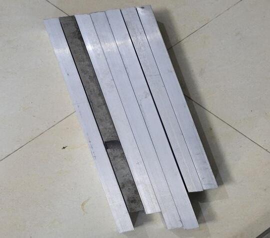
We also finalized for our design after noticing from our research that most manufacturers used a standard build volumeof200mmx200mmx200mm.
ii. Concept Sketching and CAD Modelling
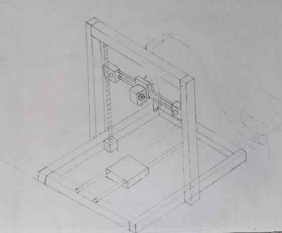
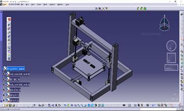
Webeganwitharough2Dhandsketchtoobtainasenseof the spatial relationship of the components. We then developed a precise 3D CAD model using CATIAV5. In the CADmodel:
The frame was dimensioned and assembled using the alu-minimumchannelsections.Standardcomponentssuch
as stepper motors, lead screws, hotend, bed, and extruder weredownloadedandpositionedwithintheassembly.


iii. Frame Machining and Assembly
OncetheCADmodelwascompleted,themachiningofthe aluminium channels was initiated in the college workshop.
The channels were cut to precise size according to the CAD drawing using a manual hacksaw prior to being smoothedfurtherusingafileandbenchgrinder.
Drilling: There were special holes marked and drilled for:
1. InstallationoftheX-axissteppermotor.
2. Permitting lead screws to travel along the Z-axis supports.
3. Attaching L-brackets to connect frame sections in rightangles.


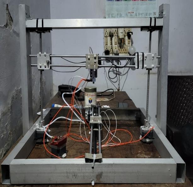
Figure 6:ActualpreparedModel
1:Componentsusedintheproject
Firmware & Calibration:
b. Key Firmware Settings:
The following parameters were updated in the Marlin firmware’s[5]Configuration.hfile:
c. Motherboard Selection: MOTHERBOARDBOARD_RAMPS_14_EFB
This sets the controller board configuration suitable for our RAMPS 1.4 setup (EFB: Extruder, Fan, Bed.
d. Baud Rate: BAUDRATE115200
A high baud rate ensures faster serial communication between the printer and host software.
e. Thermistor Configuration: TEMP_SENSOR_01(Hotend) TEMP_SENSOR_BED1(Heatbed)
f. Temperature Limits: HEATER_0_MAXTEMP275(Hotend) BED_MAXTEMP90(Heatbed)
g. Axis Inversion and Homing Direction: INVERT_X_DIRfalse INVERT_Y_DIRfalse INVERT_Z_DIRfalse
X_HOME_DIR-1
Y_HOME_DIR-1
Z_HOME_DIR-1
h. Endstop Logic:
X_MIN_ENDSTOP_INVERTINGtrue
Y_MIN_ENDSTOP_INVERTINGtrue
Z_MIN_ENDSTOP_INVERTINGtrue
i. Micro stepping (via hardware jumper):
All axes configured with 1/16 micro stepping using A4988drivers.
B. Steps per mm Calibration:
Precisemovementiscriticalfordimensionalaccuracy.We usedaniterativemethodtocalibratethe steps/mm forX, Y,Zaxesandtheextruder.
Formula to calibrate steps per mm: ew teps mm Current teps mm (ExpectedMovement ctualMovement )
X-Axis (Belt Driven):
Initialvalue:100
Commandedmove:60mm
ActualMovement(Measured):150mm
Newvalue: ew teps mm 1 ( 1 )

International Research Journal of Engineering and Technology (IRJET) e-ISSN: 2395-0056
Volume: 12 Issue: 05 | May 2025 www.irjet.net p-ISSN: 2395-0072
New Steps/mm for X-Axis 40mm
Y-Axis (Belt Driven):
Initialvalue:80mm
Commandedmove:50mm
ActualMovement(Measured):125mm
Newvalue: ew teps mm 1 ( 1 )
New Steps/mm for X-Axis 40mm
Z-Axis (Lead Screw Driven):
With 8mm pitch, 1.8° NEMA17 motor, and 1/16 micro stepping[3].
tepspermm
Motor tepsper ev Microstepping ead
Steps/mm for Z-Axis 400mm
Extruder (E-Axis):
Loadedfilament80mmusingG1E80F100
Measuredextrusion:95.4mm
Newsteps/mm:
ew teps mm 1 ( 1 )
Steps/mm for E-Axis
Table 2: Alterationsforstepspermmofaxes
Axis Steps/mm
Calibration was repeated at least 2–3 times to eliminate backlash and measurement inconsistencies.
C. Cura Profile
Table 3:TablerepresentingCuraslicerprofileofour3D printer
Parameter Value Description
LayerHeight 0.1mm Fine quality print for better detail
WallLineCount 3 Strong outer walls and better surfacefinish
InfillDensity 20% Balanced strength and print time
InfillPattern Grid / Cube Suitable for uniform internal strength
Printing Temperature 200°C IdealforPLA+filament
Build Plate Temperature 60°C Improves bed adhesion and reduceswarping
PrintSpeed 48 mm/s
Optimized for quality and reliability
Retraction Distance 6.5mm PreventsstringinginBowdenstylesetups
RetractionSpeed 25 mm/s
Moderate speed to avoid filamentgrinding
Initial Layer Height 0.3mm Improves first layer adhesion andtolerance
CoolingFanSpeed 100% Enhances print quality by coolingPLA+effectively
4. RESULT & DISCUSSION
A. Successful Prints
Throughout the project, various models were printed to evaluate and validate the performance of the assembled 3D printer. Among the successful prints: Low-Poly Ganesha Model: Printed using PLA+ filament with a layerheightof .1 mmandaprinttimeofapproximately 2 hours and 30 minutes. The model was successfully printedwithsupport,showingcleandetailsandminimal stringing.

International Research Journal of Engineering and Technology (IRJET) e-ISSN: 2395-0056
Volume: 12 Issue: 05 | May 2025 www.irjet.net p-ISSN: 2395-0072

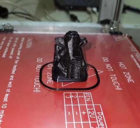
2:LowpolyLordGaneshamodelprintedwith supports
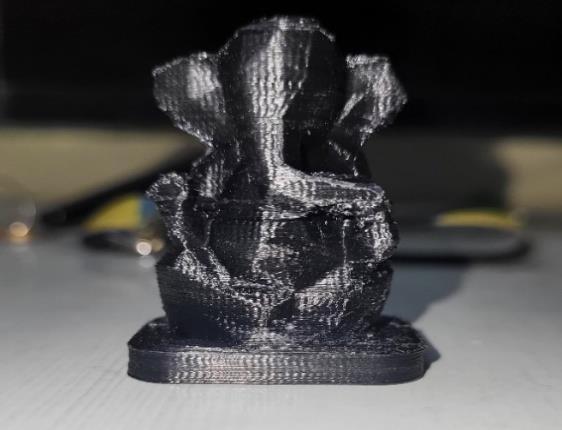

3:LowpolyLordGaneha3Dmodelwithremoved supports

4
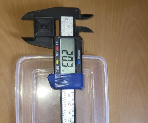
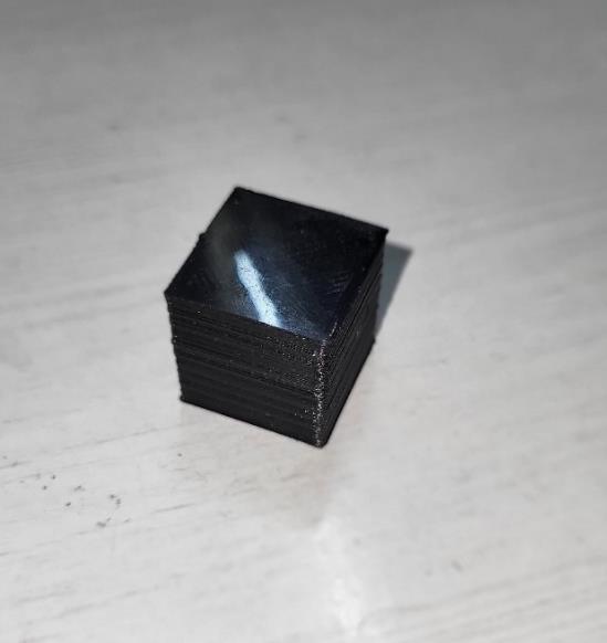
20 × 2 Calibration Cube: Accurately printed, measured exactly mm on all axes, confirming proper dimensionalcalibration.

Figure 5:Calibrationcubemeasuredwithdigitalvernier caliper
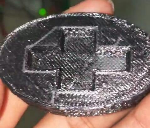
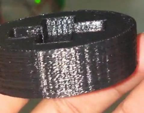
B. Initial Successful Print: Initial Successful Print: BeforewemodifiedourCuraprofile,weachievedourfirst successful print a symbol-printed badge with a crosspatternedraiseddesign. This3Dprintaffirmedthat:
The motion system and firmware were functioning well.
Filamentfeedingandextrusionwereconsistent.
Bedadhesionandfirst-layerprintqualityweregood.
Eventhoughthedetailingandsurfacefinishwereminimal, it was where the printer transitioned from mechanical configuration to functional product. This led to additional optimizationandslicingparameters.


Volume: 12 Issue: 05 | May 2025 www.irjet.net p-ISSN: 2395-0072

C. Print Quality Evaluation
Thefirsttestprintsshowedunevenlayeralignmentand dimensional errors, particularly in the calibration cube. Subsequent to prolonged tuning, cura profile updates, and firmware upgrades, print quality dramatically improved.Themainobservationsare:
Layer Adhesion: Robust and consistent across best printing temperature (200°C for PLA+) and bed temperature(60°C)[2].
Surface Finish: Smooth surface obtained with a .1 mm layerheightand3walllines.
Support Structures: There was testing both with and without support for more complex models, and both solutionswerefoundacceptablewithexcellentoverhang management.

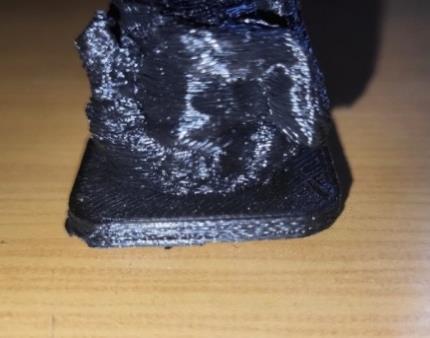
Figure 8: VisiblelayerlinesonincompleteLordGanesha 3Dmodelduetoabsenceofsupports

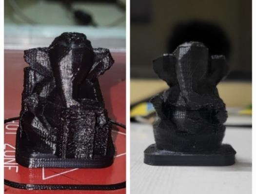
9:Bettersurfacefinishduetopresenceofsupports onLordGanesha3Dmodel
5. CONCLUDING REMARKS AND SCOPE FOR
FUTURE WORK
A. CONCLUSION
Thedevelopment andoptimizationofa low-cost FDM 3D printer for prototyping and educational purposes have demonstrated great potential in demystifying additive manufacturing technology. By utilizing open-source components such as the Arduino Mega 2560, RAMPS 1.4, and NEMA 17 stepper motors, the project effectively demonstrates how low-cost systems can deliver reliable performance and print quality. The research confirms that with proper mechanical alignment, firmware configuration, and slicing profile adjustments, low-cost printers can deliver results comparable to commercial systems.
The initial test phase revealed some hardware and software-levelissueslikeextruderstepskippingandinfill irregularities.Theseissueswereresolvedwithsystematic debugging via firmware adjustment, Bowden tube adjustment, and retraction setting adjustment, particularly in Ultimaker Cura. Following these adjustmentmeasures,printslikethecalibrationcubeand the low-poly Ganesha model print were successfully printed,which demonstrated the system to bestableand accurate. The follow-up successful print ensured the validity of the custom print profile, proper bed leveling, and extrusion calibration, again emphasizing the importanceofiterativetesting.
Additionally, the hands-on experience significantly developed the group's working understanding of stepper driver control, G-code interpretation, and firmware features like Z-babystepping, which are critical for adjusting the first layer in real-time. These activities developed not just technical skills but also valuable team andproblem-solvingskillsrequiredforrolesinindustrial or research-focused design and production.

International Research Journal of Engineering and Technology (IRJET) e-ISSN: 2395-0056
Volume: 12 Issue: 05 | May 2025 www.irjet.net p-ISSN: 2395-0072
In general, the effective deployment of the custom FDM 3D printer confirms the viability of open-source technology in realistic engineering simulation and prototyping settings. Withcontinued improvement, these systems have the potential to offer scalable solutions to rapid manufacturing, design verification, and experimentation education, all within the contexts of affordabilityandaccessibility.
B. SCOPE FOR THE FUTURE WORK
Building onthis project,a numberofdirections forthe 3D printer system's expansion and practical improvementcanbeinvestigated:
1) Auto bed leveling integration: By doing away with the need for manual leveling, an automatic bed leveling sensor, like BLTouch or a capacitive probe, would improve print consistency and cut down on setuptime.
2) Power Loss Recovery and Filament Run-out
Detection: Reliability would be increased and the printer would be more production-ready if the firmware were improved to support functions like filamentrun-outdetectionandpower-lossrecovery.
3) AI-Based First Layer Monitoring System: An AIenabled camera system that can identify first layer flaws in real time and notify users or halt the print couldbeafutureadditiontothefirstlayermonitoring system. This would increase first-layer dependability andcutdownonmaterialwaste.
6. REFERENCE
1) Gawel, T. G. (2020). Review of additive manufacturing methods.SolidStatePhenomena,308,1-20.
2) Aranda, S., & Feeney, D. (2018).3D Printing Failures: 2019EditionHowtoDiagnoseandRepairALLDesktop3D PrintingIssues.Independentlypublished
3) GAYATRI, M. G. 3D PRINTER USING FUSED DEPOSITIONMODELING.
4) Al-Maliki, Jabbar Qasim, and Alaa Jabbar Qasim AlMaliki. “The processes and technologies of 3D printing.” International Journal of Advances in Computer Science andTechnology4.10(2015):161-165.
5)Patil, Dr Rajashekar, et al. "Economical 3d Printer by Adopting FDM Technique." International Journal of MechanicalEngineeringandTechnology8.4(2017).
