International Research Journal of Engineering and Technology (IRJET)
e-ISSN: 2395-0056
Volume: 12 Issue: 05 | May 2025
p-ISSN: 2395-0072
www.irjet.net
INVESTIGATION OF AIR INTAKE DESIGN FOR ENHANCED PERFORMANCE IN LAND-LAUNCHED AND SUBMARINE-LAUNCHED CRUISE MISSILES Satyajit Panigrahy1, Saswat Kumar Panda2, Pattabhi Ramaiah Budarapu3 Manas Mohan Mahapatra4 1,2 PhD research scholar at School of Mechanical Sciences ,IIT, Bhubaneswar, Argul, India 3 Associate Professor at School of Mechanical Sciences ,IIT, Bhubaneswar, Argul, India 4 Professor at School of Mechanical Sciences ,IIT, Bhubaneswar, Argul, India
---------------------------------------------------------------------***---------------------------------------------------------------------
Abstract - This study addresses the critical, yet often
degradation and compromises overall compressor performance, highlighting the critical need for distortion mitigation.
overlooked, impact of air intake design on cruise missile performance. Traditional analyses frequently neglect detailed intake geometry, resulting in approximate evaluations. This research employs Computational Fluid Dynamics (CFD) to optimize integrated air intakes, focusing on minimizing inlet distortion in both land and submarinelaunched cruise missiles. B-spline curve-fitted geometries with varying curve factors were analyzed, demonstrating superior performance compared to baseline designs. The study highlights the significance of specialized intake shapes, including those with trapezoidal or elliptical openings and sharp edges, which generate vortices to improve airflow and reduce drag. Optimized designs enhance stealth capabilities by minimizing radar reflection and contribute to smoother engine operation. By incorporating detailed intake analysis, this research provides a more realistic performance assessment, yielding practical results for gas turbine development. The findings demonstrate that B-spline curve-fitted air intakes effectively minimize circumferential distortion at transonic speeds, offering a promising approach to enhance cruise missile efficiency and overall performance. This study emphasizes the importance of integrating optimized distortion conditions into gas turbine inlet analyses, contributing to the development of more effective and efficient cruise missile propulsion systems
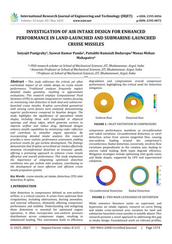
Uniform flow
Distorted flow
FIGURE 1 : INLET DISTORTION IN COMPRESSORS compressor performance, manifests as circumferential and radial variations. Circumferential distortion, or swirl distortion, arises from uneven tangential flow, causing non-uniform loading around the compressor's circumference. Radial distortion, conversely, involves flow variations perpendicular to the rotation axis, leading to uneven radial loading. Both types degrade efficiency. Mitigation strategies include optimizing inlet guide vanes and blade shapes, supported by CFD and experimental validation.
Key Words: cruise missile, air intake, distortion, CFD, inlet distortion, B-spline.
1.INTRODUCTION Circumferential Distortion
Inlet distortion in compressors defined as non-uniform airflow, is a critical concern. It arises from upstream flow irregularities, including obstructions, ducting anomalies, and external influences, ultimately affecting compressor performance and stability. Understanding and mitigating these distortions is essential for optimized engine operation., it often incorporates non-uniform pressure distributions across compressor stages, resulting in imbalanced loading. This unevenness leads to efficiency
© 2025, IRJET
|
Impact Factor value: 8.315
Radial Distortion
FIGURE 2 : TWO MAIN CATEGORIES OF DISTORTION While extensive literature exists on supersonic and hypersonic air intake regimes, research on curve fitting and intake cross-sectional area variation for land and submarine-launched cruise missiles is notably absent. This research presents a novel approach to addressing this gap in intake design. Foundational work on relevant profiles,
|
ISO 9001:2008 Certified Journal
|
Page 1574