
International Research Journal of Engineering and Technology (IRJET) e-ISSN: 2395-0056
Volume: 12 Issue: 06 | Jun 2025 www.irjet.net p-ISSN: 2395-0072
![]()

International Research Journal of Engineering and Technology (IRJET) e-ISSN: 2395-0056
Volume: 12 Issue: 06 | Jun 2025 www.irjet.net p-ISSN: 2395-0072
Prof. Yogesh R. Naik
Electrical Engineering
Sanjeevan Group of Institutes
Pujari Uttam Tanaji
Electrical Engineering
Sanjeevan Group of Institutes Kolhapur, Maharashtra Kolhapur, Maharashtra yogesh.naik@seti.edu.in uttampujari10@gmail.com
Charaple Rohini Pandurang Kumbhar Adinath Jalindar
Electrical Engineering
Sanjeevan Group of Institutes
Electrical Engineering
Sanjeevan Group of Institutes Kolhapur, Maharashtra Kolhapur, Maharashtra rohinicharaple5@gmail.com adinathkumbhar96@gmail.com
Abstract - Thisprojectfocusesontheexperimentalanalysis of a single-phase half-controlled converter, a critical component in power electronics, often used in applications suchasDCmotorcontrol,batterycharging,andpowersupply systems. The study examines the operation of the converter with various load types, including resistive (R), resistiveinductive(RL),andresistive-inductivecapacitive(RLC)loads. The converter circuit utilizes a combination of thyristors and diodes to achieve controlled rectification and freewheeling actions. Key observations include the analysis of output voltage and current waveforms under different firing angles, demonstrating the impact of load and firing delay on performance. Through theoretical discussion, numerical problem-solving, and practical waveform observations, the project highlights the efficiency and operational characteristics of the single-phase half-controlled converter. Safetyprecautionsandproceduralguidelinesensureaccurate data collection and a safe working environment. This study aims to deepen understanding of controlled rectification techniques and their implications in practical scenarios
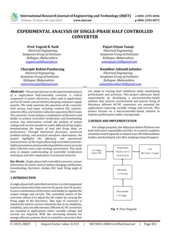
Key Words: Single-phasehalf-controlledconverter,power electronics,DCmotorcontrol,batterycharging,rectification, freewheeling, thyristors, diodes, RLC load, firing angle of time.
Asingle-phasehalf-controlledconverterisavitalcomponent inpowerelectronicsthatconvertsACpowerintoDCpower. Itusesacombinationofthyristorsanddiodestoregulatethe output voltage and current. The controlled nature of the converterallowsittoadjust theDCoutput byvaryingthe firing angle of the thyristors. This type of converter is extensivelyusedinvariousindustriesduetoitssimplicity, reliability,andcost-effectiveness.EfficientAC-DCconverters are essential in applications where variable voltage and current are required. With the increasing demand for energy-efficientsystems,thereisaneedforconvertersthat
can adapt to varying load conditions while maintaining performance and precision. This project addresses these requirements by developing a microcontroller-based solution that ensures synchronized and precise firing of thyristors efficient AC-DC converters are essential for applications requiring variable voltage and current. This project focuses on a microcontroller-based solution to enhanceperformanceundervaryingloads
Forcollegepurposes,theAdhyayanOnlinePlatformwas builtwithmoreresponsibleactivities.Itisusedinacademic schedulesmostfrequentlyinrelatedways.Wefollowedthese studiesanddevelopedakitafterstudyingresearchpapers

Fig -1:FlowDiagram

International Research Journal of Engineering and Technology (IRJET) e-ISSN: 2395-0056
Volume: 12 Issue: 06 | Jun 2025 www.irjet.net p-ISSN: 2395-0072
3.1 Main Unit: The main unit contains all the power electronics,includingthethyristors,diodes,andassociated components.TheinputACvoltageisfedintotheunit,and theoutputDCvoltageisdeliveredtotheload.
3.2 Load Bank:Theloadbankiswheredifferentloads(R, L,C)areconnectedtoobservetheireffectontheconverter. The load can be adjusted by varying the resistance, inductance,andcapacitance,dependingontheexperiment.
3.3 Firing Control Section: The firing control section, which consists of the microcontroller and associated circuitry,isresponsiblefordetectingthezero-crossingofthe input voltage and generating the firing pulses for the thyristors.Themicrocontrolleralsoadjuststhedelaytimeto controlthefiringangle(α\alphaα).
3.4 Voltage Measurement: Measurementoftheoutput voltageisdoneusingavoltmeteroroscilloscopeacrossthe load.Theoutputvoltageisaffectedbythefiringangleand thetypeofloadused.
3.5 Current Measurement: The current is measured acrosstheloadusingacurrentprobeorbycalculatingthe voltageacrossaknownresistor.
Connectthe8-pinsocketfromthemainunittotheload bank.Patchtheloadbankwiththedesiredload(R,L,C)as pertheexperiment'srequirements.EnsuretheACvoltage sourceiscorrectlyconnected,andthepowersupplyforthe microcontrollerissetto5V.
4.1 Zero-Crossing Detection and Firing Angle
Control: The microcontroller detects the zero-crossing point of the input AC waveform and generates the firing pulsesforthethyristorsinsyncwiththeACsupply.
Thefiringanglecanbevariedusingapotentiometeror othercontroldevices.
4.2 Waveform Observation: Connecttheoscilloscopeto the output terminals to observe the waveforms of the AC input,outputDC,andloadvoltage.
Vary the firing angle and observe how it affects the outputvoltageandcurrentwaveforms.
Thisisthemaincircuitsetupofourproject.Itdisplaysallthe essential components and connections used in the experimentalanalysis.


International Research Journal of Engineering and Technology (IRJET) e-ISSN: 2395-0056
Volume: 12 Issue: 06 | Jun 2025 www.irjet.net p-ISSN: 2395-0072
5.1 Resistive (R) Load: Bridge Patching Diagram for Resistive(R)Load

-6:BridgePatchingDiagramforResistive(R)Load Connection
CircuitConfigurationforResistive(R)Load


-8:OutputVoltageandCurrentWaveformsfor Resistive(R)Load
5.2 Resistive-Inductive (RL) Load: Bridge Patching DiagramforResistive-Inductive(RL)Load

-9:CircuitConfigurationforResistive-Inductive(RL) Load
CircuitConfigurationforResistive-Inductive(RL)Load

Resistive-Inductive (RL)Load
WaveformAcross‘Resistive-Inductive(RL)’Load

Fig -11:OutputVoltageandCurrentWaveformsfor Resistive-Inductive(RL)Load
2025, IRJET | Impact Factor value: 8.315 |

International Research Journal of Engineering and Technology (IRJET) e-ISSN: 2395-0056
Volume: 12 Issue: 06 | Jun 2025 www.irjet.net p-ISSN: 2395-0072
5.3 Rresistive-Inductive-Capacitive (RLC) Load:
BridgePatchingDiagramforResistive-Inductive-Capacitive (RLC)Load

Fig -12:BridgePatchingDiagramforResistive-InductiveCapacitive(RLC)LoadConnection
Circuit Configuration for Resistive-Inductive- Capacitive (RLC)Load

Fig -13:CircuitConfigurationwithResistive-InductiveCapacitive(RLC)Load
Waveform Across ‘Resistive-Inductive-Capacitive Load (RLC)’Load

Fig -14:OutputVoltageandCurrentWaveformsfor Resistive-Inductive-Capacitive(RLC)Load
5.1 Results for Resistive (R) Load:
5.2 Results for Resistive-Inductive (RL) Load:
5.3 Results for Resistive-Inductive-Capacitive (RLC) Load:
6.ACKNOWLEDGEMENT:
Thisprojectsuccessfullydemonstratestheworkingand performance of a single-phase half-controlled converter under various load conditions. By analyzing waveform characteristics and the effects of different firing angles, it provides a comprehensive understanding of controlled rectification. The microcontroller-based firing control enhances precision and adaptability in real-world applications.
7.CONCLUSION
WesincerelythankourfacultyguideandtheElectrical Engineering Department for their constant support and guidancethroughoutthisproject.Wealsoacknowledgethe resourcesand assistanceprovided by thelaboratorystaff, whichwere essential forthesuccessful completionofthis study.

International Research Journal of Engineering and Technology (IRJET) e-ISSN: 2395-0056
Volume: 12 Issue: 06 | Jun 2025 www.irjet.net p-ISSN: 2395-0072
[1] MuhammadH.Rashid,"ControlandOperationofSinglePhase Controlled Rectifiers," in Proceedings of IEEE PowerElectronicsSpecialistsConference(PESC),1986, pp.251–257.
[2] BhimSingh,SanjeetDwivedi,"PerformanceAnalysisof Single-PhaseHalf-ControlledRectifierswithResistiveInductiveLoad,"inIETPowerElectronics,vol.2,no.4, 2009,pp.251–261.
[3] G. K. Dubey, "Phase-Controlled Rectifiers: A General Review,"inIEEETransactionsonIndustrialElectronics, vol.29,no.3,1982,pp.179–187.
[4] L. Malesani and P. Tenti, "Performance Evaluation of ControlledRectifierswithActiveLoadManagement,"in IEEE Transactions on Power Electronics, vol. 4, no. 2, 1989,pp.159–168.
[5] C.A.Nassif,S.M.A.Cruz,"ModelingandSimulationof Single-Phase Rectifiers for Power Quality Studies," in InternationalJournalofPowerElectronics,vol.3,no.2, 2011,pp.137–150.
[6] G. K. Dubey, S. R. Doradla, A. Joshi, R. M. K. Sinha, "Thyristor-BasedPowerElectronicsCircuits,"NewAge International,2004.
[7] Muhammad H. Rashid, "Power Electronics: Circuits, Devices,andApplications,"4thed.,PearsonEducation, 2014.
[8] P.S.Bimbhra,"PowerElectronics,"KhannaPublishers, 2012.
[9] https://circuitdigest.com/tutorial/single-phase-halfcontrolled-rectifier
[10] https://www.electrical4u.com/single-phase-half-wavecontrolled-rectifier
BIOGRAPHIES


Prof.YogeshR.Naik
ElectricalEngineering
SanjeevanGroupofInstitutes Kolhapur,Maharashtra yogesh.naik@seti.edu.in
CharapleRohiniPandurang
ElectricalEngineering
SanjeevanGroupofInstitutes Kolhapur,Maharashtra rohinicharaple5@gmail.com


PujariUttamTanaji
ElectricalEngineering
SanjeevanGroupofInstitutes Kolhapur,Maharashtra uttampujari10@gmail.com
KumbharAdinathJalindar
ElectricalEngineering
SanjeevanGroupofInstitutes Kolhapur,Maharashtra adinathkumbhar96@gmail.com