ENHANCING THE EFFICIENCY AND QUALTY OF PIPELINE WELDING USING REGULATED METAL DEPOSITION (RMD) TECHN

Page 1


International Research Journal of Engineering and Technology (IRJET) e-ISSN:2395-0056

Volume: 12 Issue: 06 | Jun 2025 www.irjet.net p-ISSN:2395-0072

ENHANCING THE EFFICIENCY AND QUALTY OF PIPELINE WELDING USING REGULATED METAL DEPOSITION (RMD) TECHNIQUES

1M.Tech. (ME) Scholar, Department of Mechanical Engineering, Goel Institute of Technology and Management Lucknow, Uttar Pradesh, India

2Assistant Professor, Department of Mechanical Engineering, Goel Institute of Technology and Management Lucknow, Uttar Pradesh, India

Abstract: The global demand for oil and gas continues to rise, leading to increased construction of highstrength transmission pipelines, primarily using low alloy steel. Traditional welding methods such as Gas Metal Arc (GMA) and Gas Tungsten Arc (GTA) welding are widely used in pipeline fabrication. However, these techniquespresentchallengessuchaspoorweldquality, highspatter, porosity, andlow productivity, particularly due toa shortage ofskilled welders. WhileGTA welding offers excellent quality for root passes, its low welding speed limits its suitability for mass production. To addresstheseissues,advancedweldingtechnologiesare being explored, with Regulated Metal Deposition (RMD) emerging as a promising alternative. RMD offers smoother arc control, better weld quality, and faster operation,makingitmoreaccessibleandefficient. This dissertation focuses on experimentally analyzing theeffectsofRMDweldingparameters namelywelding current, voltage, and gas flow rate on low alloy steel usingmetal-coredfiller wires.Output responsesstudied include heat-affected zone (HAZ), depth of penetration (DOP), bead width (BW), and bead height (BH). A Taguchi L25 orthogonal array was used to design experiments, conducted on a Miller ‘Continuum 500’ machine. ANOVA was applied to assess the significance ofeachvariable.Duetothe conflicting natureofdesired outcomes(lowHAZ,BW,BHandhighDOP),optimization ofweldingparametersisessentialforachievingthebest performance. This study aids in identifying optimal welding conditions for improved efficiency and weld qualityinpipelineapplications.

Keywords- Welding; GMA welding; RMD welding; Low alloy steel; Heat-affected zone; Depth of penetration; Bead width; Bead height; ANOVA; Optimization; Microstructure; Optical microscopy; SEM-EDX analysis; Micro-hardness;Tensiletest;Impacttest

1.

INTRODUCTION

Technological developments are pushing the manufacturingandconstructionsectorstoprovidehighquality, sustainable products at competitive pricing in today's fast-paced world. Real-world applications frequentlycallforassembly,eventhoughthemajorityof

goods are initially designed as separate parts. To produce useful, dependable, and reasonably priced components,industriesincludingautomotive,aerospace, petrochemical, medical, culinary, and energy commonly need to combine materials of different sorts and thicknesses.

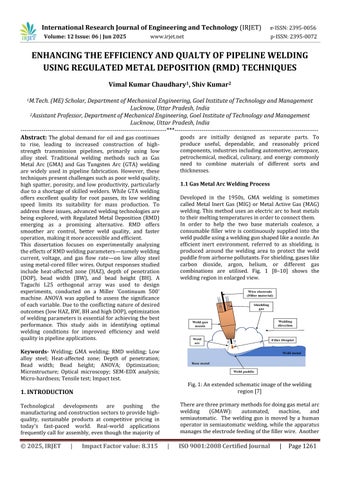
1.1 Gas Metal Arc Welding Process

Developed in the 1950s, GMA welding is sometimes called Metal Inert Gas (MIG) or Metal Active Gas (MAG) welding.Thismethodusesanelectricarc toheatmetals totheirmeltingtemperaturesinordertoconnectthem. In order to help the two base materials coalesce, a consumable filler wire is continuously supplied into the weldpuddleusingaweldinggunshapedlikeanozzle.An efficient inert environment, referred to as shielding, is produced around the welding area to protect the weld puddlefromairbornepollutants.Forshielding,gaseslike carbon dioxide, argon, helium, or different gas combinations are utilised. Fig. 1 [8–10] shows the weldingregioninenlargedview.

Fig.1:Anextendedschematicimageofthewelding region[7]

Therearethreeprimarymethodsfordoinggasmetalarc welding (GMAW): automated, machine, and semiautomatic. The welding gun is moved by a human operator insemiautomatic welding, while the apparatus managestheelectrodefeedingofthefillerwire. Another

International Research Journal of Engineering and Technology (IRJET) e-ISSN:2395-0056

Volume: 12 Issue: 06 | Jun 2025 www.irjet.net p-ISSN:2395-0072

nameforthistechniqueishandheldwelding. Inmachine welding, the operator mostly uses commands to control the robot's movements rather than physically assisting withtheweldingprocess.Theweldinggunisinstalledon a robot. On the other hand, automatic welding requires little to no human monitoring because the equipment control system does the welding without requiring any physicalmodifications[5,10].

1.2. Regulated Metal Deposition (RMD) Process

Based on the short-circuiting theory of metal transfer, Miller Electric Mfg. unveiled a novel welding process in 2004calledRegulatedMetalDeposition(RMD)welding. A controlled short-circuiting process, which electronicallycontrolstheweldcurrentateverystageof metaltransfer,isafeatureofRMDwelding,animproved form of GMA welding. An inventive computer program that tracks the filler wire current during each shortcircuiting phase powers this operation. RMD welding can anticipate and modify the occurrence of short circuits, lowering the welding current for stable metal transfer, thanks to developments in power supply sources,digitaltechnology,andcomputerprogramming

Fig.2:AstandardRMDcycledepicts(a)thedefinite stagesofmetaltransfer,and(b)theamperagewaveform

2.

LITERATURE REVIEW

Finding the ideal balance between quality and productivity is crucial in production. This implies that manufacturing rates must satisfy demand without compromising important elements of quality, like surface finish and dimensional precision. In order to

tacklethisdifficulty,optimisationhasbeenimplemented to minimise expenses and time while offering the most effectiveresolutionforcurrentissues.Optimisationfinds the bestmachinesettings froma specifiedsamplespace by maximising or minimising an objective function. A processorproduct'soveralleffectivenessandqualityare assessedusinganumberofperformancecharacteristics. Finding the ideal machine settings that produce the required performance is the main objective in manufacturing. Therefore, optimising the link between input factors and output reactions in the process or productisessential.

Itisinsufficienttoconcentrateononlyonegoalatatime because this ignores the influence of other concurrent variables. Multiple response optimisation is therefore required to evaluate the process or product in its entirety. Optimisation is necessary in all processes, including welding. Optimising welding performance is essential for accurately forecasting process variables, which helps to cut down on the time and expense of experimental work. The performance of welding has beenoptimisedusingavarietyofmethods.Forinstance, Ghosh et al. joined two different grades of steel, AISI 316L andAISI409,usingmetal inertgas(MIG)welding. The impact of several welding parameters, such as gas flow rate (GFR), nozzle-to-base material distance, and current (A), on the yield strength (YS) and ultimate tensile strength (UTS) of the welded materials was investigated using the Taguchi orthogonal L9 array. The data was analysed using the Taguchi desirability approach, and a confirmatory test was carried out. Similartothis, Vedrtnam andSingh employed Response Surface Methodology (RSM) and Genetic Algorithms (GA) to validate the results of their study on current, speed, nozzle-to-base material distance, and voltage as inputparametersforsubmergedarcweldingofstainless steel. In order to combine dissimilar aluminium alloys (AA5083 and AA2219), Mastanaiah et al. used electron beam welding. They also investigated the relationship betweendifferentprocessparametersandthegeometry of the weld beads. Effective weld thickness was determined to be the weld parameter that had the greatestimpactontensilebreakingload.

Withweldingcurrent,weldingvoltage,andGFRasinput variables,Baloyietal.usedanintegratedTaguchi-ANFIS techniquetooptimisethetensilestrengthof3mmthick MIG-welded AISI1008 mild steel plates. The most important impact to tensile strength was found to be weldingvoltage(57.3%),followedbycurrent(20%)and gas flow rate (10%), according to Analysis of Variance (ANOVA). Palani and Arunprasad used a combination of Principal Component Analysis (PCA) and RSM-Grey Relation Analysis (GRA) to optimise plasma arc welding (PAW) for connecting Ti-3Al-2.5V and AA8011-H24.

International Research Journal of Engineering and Technology (IRJET) e-ISSN:2395-0056

Volume: 12 Issue: 06 | Jun 2025 www.irjet.net p-ISSN:2395-0072

They discovered that the most important element affecting quality at the ideal level was welding speed. Aravindetal.joinedTi6Al4Vsheetsusinglaserwelding, optimising process variables such GFR, welding speed (Ws),andlaserpower(Lp).Hardness,beadwidth(BW), and depth of penetration (DOP) were used to gauge performance. The parameters were optimised using the VIKORmethod,whichproducedtheidealvaluesofWs= 0.3m/min,Lp=1.3kW,andGFR=20LPM.

2.1. Research Gaps

The following gaps have been identified based on the aforementionedstate-of-art:

 GMA welding and GTA welding processes preferablydorootpassoncarbonsteels.

 GTA welding is recommended for root pass in welding of low alloy steels. However, limited literatureisavailableontheusageofGTAwelding forlowalloysteels.

 In addition to this, RMD welding, developed by Miller, is a novel technology, and hence, limited literatureisavailableonitsweldingpertinencyfor lowalloysteels.

2.2.

Research Objectives

Based on the identified research gaps, the objectives of the current dissertation have been formulated as follows:

 To analyze the effect of different RMD welding variables (viz. welding current, welding voltage, and gas flow rate) on weld bead geometry and morphology (mainly heat affected zone, depth of penetration, bead width, andbeadheight)forlow alloysteel.

 To examine the microstructure and mechanical characteristics of the RMD welded low alloy steel joints.

3. EXPERIMENTAL WOK

Experimentation is an essential aspect of invention, and some would say that without it, there is no invention. It refers to an intellectual investigation, i.e. the quest for validand reliableknowledge.Itis an approachin which one or more variables are actively regulated and the effectoroutcomeofthatregulationonothervariablesis monitored.Experimentscanbecarriedoutinthefieldor the laboratory. When working in a laboratory, the researcherhasdirectcontroloverthemajority,ifnotall, of the variables that might affect the experiment's results. Researchers can investigate the impacts of

differentinputfactorsviaexperimentations.Suchfactors canberegulatedandtheireffectscanbeseenintermsof certain output responses [167,168]. Experimentation, according to Boyd and Westfall [169], is a research process in which one or more variables are altered in settings that allow for the gathering of data that demonstrates the effects if any. In this context, this chapter describes the experimental work of RMD welding. Before commencement of the experiments, a few modules, viz. selection of influencing parameters, materials to be welded, how many experiments to be carried out, availability of machine setup, etc., must be discussed to execute experiments in systematic and successful manners. All these modules have been discussedbelow.

3.1 Selection of Base Material

In this work, low alloy steel plates of 500 × 150 × 6 in sizehavebeenchosentoexecutetheRMDweldingtrials. The generic name of this steel is 1¼ chrome which is commercially available as ASME SA387-11-2 and ASTM A387-11-2.Here,ASMEstandsforTheAmericanSociety of Mechanical Engineers, SA stands for Specification for Analysis,andASTMstandsforTheAmericanSociety for Testing and Materials. Table 1 exhibits the constituents ofthematerial.

Table1:ThecompositionofASTMA378-11-2steel

Low alloy chrome-moly steel is a popular variety of the steel family. It demonstrates excellent tensile strength, fatigue, creep, and corrosion-proof properties at both ambientandelevatedtemperatureenvironments.Dueto its proven experience at an elevated temperature of 500°C and above, it is widely used in power generation plants, hydrocarbon processing, coal conversion industries, and other highly stressed structural applications.It alsoservesinoil refineriesandchemical industries as a piping and tubular system owing to its excellent creep and oxidation resistance characteristics. It possesses sufficient strength to withstand the inner pressure and the high toughness ensures safety against momentary impact due to unexpected accidents. It is

International Research Journal of Engineering and Technology (IRJET) e-ISSN:2395-0056

Volume: 12 Issue: 06 | Jun 2025 www.irjet.net p-ISSN:2395-0072

highlyeffectiveinsourgasandsaltwaterapplications.It alsopossessesdecentweldabilityandhighhardenability due to its alloy contents. The availability of Chromium (Cr)contentmakesthematerial anti-corrosiveandantioxidant. Molybdenum (Mo) increases the strength and hardness of the material at elevated temperatures. Boilers, pressure vessels, superheaters, flanges, ducting, fittings, pipelines, valves, heat exchangers, ducting and piping supports, etc. are made up of these materials. Table2displaysafew essentialmechanicalandthermal propertiesofASTMA387-11-2steel.

Table2:MechanicalandthermalpropertiesofASTM

A378-11-2steel

3.2 Parametric Level Setup and DOE

To carry out the experiments correctly and systematically,itisessentialforaninvestigatortoselect theimportantvariablesandtheirrespectivelevels. In this work, the levels for welding variables, set during theexperimentation,havebeenlistedinTable3

Table3:Assigninglevelstotheweldingvariables

As the experimentation consumes lots of time and money, it is difficult to perform experiments at each parametriccombinationoftheprocessvariables.Insuch cases, the significance of the design of experiments (DOE) comes into the picture which portrays a key role inexperimentalplanningandprocessing

In this work, Taguchi’s orthogonal array (OA) model is applied because of its several advantageous characteristics. It is a robust, yet simple tool that can readily be used in a lot of engineering problems. It emphasizes the average value of performance features closetothegoalvalueratherthanonthevaluebetween specific limits, accordingly improving the quality of the

product/process. Despite its partial design, it provides equality between all levels of all variables. Therefore, in the present investigation, L25 OA was applied. Table 4depicts the total number of experimental runs along withthelevelofweldingvariables.

Table4:FormulationofDOEusingL25orthogonalarray

4. MICROSTRUCTURAL AND MECHANICAL CHARACTERIZATIONS

The study of microstructure is essential for understandingthematerial’sbehavior.Inlightofthis,an endeavor has been made to evaluate the microstructure andmechanicalcharacteristicsofRMDweldedlowalloy steel plates. The optical microscope, as well as scanning electron microscope (SEM), were used in the microstructural analysis. Mechanical characteristics of the welded specimen viz. tensile strength, microhardness,andimpactstrengthhavealsobeenstudied.A comparativestudyhasalsobeencarriedoutforthesame materialusingtheconventionalGMAweldingmethod,in whichthemicrostructureandmechanicalcharacteristics ofRMDweldedsampleshavebeencomparedtothoseof GMAweldedsamples.

© 2025, IRJET | Impact Factor value: 8.315 | ISO 9001:2008 Certified Journal | Page1264

International Research Journal of Engineering and Technology (IRJET) e-ISSN:2395-0056

Volume: 12 Issue: 06 | Jun 2025 www.irjet.net p-ISSN:2395-0072

4.1 Materials and Methods

In this study, 6 mm thick ASTM A387-11-2 steel plates, withacross-sectionalareaof240mmlengthand75mm width,havebeenjoinedtogetherusingRMDweldingand GMA welding techniques. The base metals to be joined were, first, cleaned mechanically through a steel brush and with acetone to get rid of any impurities and oxide depositsfromtheirsurfaces.Thereafter,theplateswere grinded at the edges to be joined (Fig. 3(a)) using a grinding operation. These grinded plates were, then, tackedtogether(Fig.3(b))atagapof3mmandclamped for butt welding. Tacking and clamping were done to discourageanysortofmisalignmentbetweenthem.

(a)Groovesattheedgestobejoined (b)Tackingofthe groovedsteelplates

Fig.3:Groovemakingandtackingoflowalloysteel platesforbuttwelding

RMD welding and GMA welding operations have been performed on the clamped workpieces and the gaps between the plates were filled using the “Continuum 500” welding machine at the aforementioned optimal welding combination. ‘MEGAFIL 237 M’ metal-cored electrode (1.2 mm diameter) has been used as a filler wire in both welding operations. The weld joints had 2 passes in RMD welding and 3 passes in GMA welding. The chemical structure of ASTM A387-11-2 steel and filler wire electrode has been presented in Table 9. The weldsettingsappliedinthisworkhavebeenimpartedin Table5

Table5:ThechemicalstructureofASTMA387-11-2steel andthewireelectrode

Table6:WeldsettingsforRMDandGMAwelding operations

4.2. Microstructural Analysis

The microstructure and morphology of developed phases have a noteworthy effect on the weld structure andmechanical characteristicsof the base material.The opticalmacro-graphsindicatedthreeuniquezones(base metal(BM),heataffectedzone(HAZ),andweldmetalor weld zone (WM or WZ)) with gradually evolving grain morphologies. After polishing and etching the samples with 2% Nital, the microstructures of these zones have been examined at a magnification of 200X. Fig. 4 shows the microstructure of three different zones of RMD welded low alloy steel plates in which Fig. 4(a) belongs toBM,Fig. 4(b)belongsto HAZ,andFig. 4(c)belongs to WZ.

Thepresenceofbainite(shownbytheletterB)inadark colorandferrite(representedbytheletterF)inalighter color can be seen in Fig.4(a). A fine dispersion of alloy carbidessuch asM3C, M2C, M7C3, and M23C6 may also be detected in the microstructure, but owing to their short width, their distribution is not easily observable. Here, M denotes Fe, Cr, Mo, or a mix of these elements, whereas C denotes carbon. Fig. 4(b) shows a noticeable difference in microstructure from BM to HAZ. The existence of bainitic structure can be seen in the micrograph of unaffected base material, whereas HAZ microstructures reveal a mixture of fine and coarse grains. These grains resemble acicular bainite in appearance.Theobtainedmicrostructuresaresimilarto themicrostructuresofCr-MosteelreportedbyDasetal., Ahmed et al. , Juliermes et al., and Yoo, et al. in their research of microstructure of low alloy steel. They characterized the presence of bainitic microstructure alongwithvariouscarbideprecipitates.

International Research Journal of Engineering and Technology (IRJET) e-ISSN:2395-0056

Volume: 12 Issue: 06 | Jun 2025 www.irjet.net p-ISSN:2395-0072

a) Microstructureofbasemetal

b) Microstructure of RMD welded heat-affected zone

(c)MicrostructureofRMDweldedweldzone

Fig.7:MicrostructureofRMDweldment(a)BM,(b)HAZ, and(c)WZ

In this investigation, the base material was quenched and tempered. Quenching is usually accomplished by rapidly cooling the material from its Ms temperature, and irregular grains generate as a result of the inadequate cooling rate. Martensitic structure, which is lathy in appearance and hard in character, develops when cooling rates are high enough. The grains have an adequate opportunity to reorganize themselves during tempering,resultinginadecreaseinhardness.Owingto

this, the lathy grains get transformed into spherical shapes. Due to significantly less amount of hot molten mass and the low adjacent temperatures, the WZ undergoesanidenticalquenchingcycle.Hence,theWZis subjected to an air-cooling effect owing to the short recrystallization interval, resulting in irregular harder phaseslikeuntamperedmartensite.AsaresultofPWHT, the weldments were given enough time to recrystallize, resulting in the formation of tempered martensitic in WZ, as illustrated in Fig. 4(c). This study is further supported by the outcomes of Vora and Badheka, in which the authors have examined the microstructure of A-TIG welded RAFM steel joints and reported the presenceofmartensiticcoloniesinWZ.

4.4. Micro-hardness Test

Hardness measurements reveal yet another corroboration of the aforesaid phenomena. Before heat treatment, the micro-hardness values of RMD and GMA welded samples have been presentedin Fig. 5. For GMA welded samples, the micro-hardness value is highest at around1586.2HVfortheweldzoneascomparedtothe base metal of 492.3 HV. Similarly, For RMD welded samples, the micro-hardness value is highest at around 1888.6 HV for the weld zone as compared to the base metal of 619.8 HV. These values of micro-hardness depictthatthematerialbecameveryhardafterwelding. Also, the micro-hardness value across the RMD weldment is high as compared to the micro-hardness value across the GMA weldment. The probable reason behind this may be the low heat input of RMD welding technique as compared to GMA welding. Therefore, the cooling rate of RMD welded sample was comparatively higher,leadingtotheformationofmartensiticstructures faster in the weldment. Also, as hardness increases, brittleness increases, and toughness decreases. Therefore, post-weld heat treatment is much needed in suchcases.

After heat treatment, a significant drop in microhardnessvaluesofRMDandGMAweldedsamplescanbe observed in Fig. 6. For GMA welded samples, the hardnessvalueishighestataround260HVfortheweld zoneascomparedtothebasemetalof194HV.Similarly, For RMD welded samples, the hardness value is highest ataround 226 HV for the weldzoneas compared to the base metal of 160 HV. The base material exhibited rounded grains due to tempering and hence lower hardness was observed as expected. The HAZ region exhibited a mix of coarse and fine microstructures leading to an increasing trend in hardness values. However, a phenomenal difference between the weld zone hardness values of RMD and GMA weldments was observed. The reason behindthe high hardness value of the weld zone in GMA weldments is the formation of irregularandhardermartensiticstructures.

International Research Journal of Engineering and Technology (IRJET) e-ISSN:2395-0056

Volume: 12 Issue: 06 | Jun 2025 www.irjet.net p-ISSN:2395-0072

Fig.5:Micro-hardnessvaluesofRMDandGMAwelded samplesbeforeheattreatment

Fig.6:Micro-hardnessvaluesofRMDandGMAwelded samplesafterheattreatment

These obtained hardness values before heat treatment and after heat treatment show a similar trend of hardness values obtained in a couple of studies for the saidmaterialusingdifferentweldingtechniques.

4.4. Tensile Test

Theoutcomesoftensiletestingatroomtemperatureare presented According to previous studies and international standards, the permissible range of ultimate tensile strength (UTS) for ASTM A-370-11-2 material is 515-690 MPa. Also, the yield strength (YS) should not be less than 310 MPa. Samples welded with both welding techniques live up to this scale. As shown inTable7,theaverageobtainedvaluesofYSandUTSof RMD welded samples are 458 MPa and 554 MPa, respectively. Similarly, The YS and UTS values of GMA weldedsamplesare423MPaand523MPa,respectively. The outcomes also reveal that the RMD welded samples

displaybetterYSandUTSthantheGMAweldedsamples. Animprovementof14.68%inYSand5.92%inUTShas beennoticedforRMDweldedsamplesoverconventional GMA welding samples. The tensile tests performed over RMD welded tensile test coupons and GMA welded tensiletestcouponshavebeenillustratedinFig.7

Table7:Tensilepropertiesofweldedplates (a) (b)

Fig.7:Macrographsdisplayingtherupturesitesinthe tensiletestspecimensextracted

from (a) RMD welded samples, and (b) GMA welded samplescIn all tensile tests, the specimens showed the behavior as expected. The rupture in all specimens occurred in base metal, closer to the end of the gauge length but away from the weld zone. This shows that thattheweldstrength wassatisfactoryandmuchbetter thanthestrengthofthebasemetal.Also,alltheruptured specimens exhibited the necking phenomenon before failuretookplace.Thiscan bevindicatedbyobserving a significant decrease in the cross-sectional area around the place of rupture. This aspect characterizes the presence of ductile behavior in the weldments. This behavior was anticipated in this form of steel. Although

International Research Journal of Engineering and Technology (IRJET) e-ISSN:2395-0056

Volume: 12 Issue: 06 | Jun 2025 www.irjet.net p-ISSN:2395-0072

the welding imparts microstructural changes in the material, it had no noticeable impact on the material's mechanicalproperties.

Theseresultsareinagreementwiththeearlierfindings. Liuetal.studiedtheeffectsofPWHTon12Cr1MoVsteel pipes and found the YS and UTS of the welded joints as 427 MPa and 574 MPa, respectively. The fracture was observedinthebasemetalsdueto theirlowerstrength. Jorge et al. welded high strength low alloy steel plates using the SMAW and evaluated their mechanical properties. The authors found the YS and UTS of the weldedmaterialsas415MPaand502MPa,respectively. Thestudyfurtherreportsabouttheformationofcupand cone phenomenon during tensile testing and observes the rupture in base metal, articulating the ductile behavioroftheweldedmaterial.AstudydonebyAhmed et al. on Cr-Mo boiler steel reveals the occurrence of failure in base metals during tensile testing. The YS of the welded specimens ranges from 314.38 MPa to 377.14MPaandUTSrangesfrom538.27MPato580.75 MPa.

A further study done by Vora and Badheka talks about the occurrence of failure in base metal during tensile testing of A-TIG welded RAFM steel plates. The authors alsofounda significantabatement in the cross-sectional areaatthefailurepointbeforerupturinghappened,thus revealing the concept of ductile failure. For 1Cr-0.5Mo steel, Masuyama also finds the values of YS and UTS as 220MPaand415MPa,respectively.Afewmorestudies thatcomeoutwithsimilartheories.

4.5. Impact Test

The CVN impact test of all weld specimens was performedatroomtemperature.Theaveragetoughness values of three different weld specimens for both welding methods have been tabulated in Table 8. These values demonstrate that the RMD welded plates have comparatively higher impact toughness than GMA welded plates. The outcomes of the Charpy impact test havebeenshowninFig8

Table8:Impactpropertiesofweldedplates

The obtained values of the CVN impact tests were compared with the permissible standards of API (American Petroleum Institute) 1104. As per the API1104,thelowestpermittedvaluefortheCVNtestis40J. GMA welded samples failed to meet this criterion, whereasRMDweldedsamplesmet.Table 14showsthat RMDweldedsampleshaveanaverageimpacttoughness of 49.70 J, whereas GMA welded samples have an average impact toughness of 25.06 J. RMD welded samples exhibited almost double the impact toughness ofGMAweldedsamples,accordingtothesefindings.

(b)

Fig.8:Charpyimpactteston(a)RMDweldingsamples, and(b)GMAweldingsamples

5. CONCLUSIONS AND FUTURE SCOPE

5.1 Conclusions

This work accesses the effect of RMD welding variables namely welding current, welding voltage, and gas flow rateonoutputresponsesviz.heataffectedzone,depthof penetration, bead width, and bead height for low alloy steelthroughextensiveexperimentationandanalysis.To lessen the number of experimental trials but choosing samples from a big decision space, Taguchi’s L25 orthogonal array has been applied to develop the data set by means of experimentation. ANOVA test has been performed for evaluating the parametric influence of RMD welding variables on each output response. TOPSIS-Taguchi approach, PCA-Taguchi approach, and Raoalgorithmshavebeenadoptedtoassesstheoptimal welding combination during simultaneous optimization

International Research Journal of Engineering and Technology (IRJET) e-ISSN:2395-0056

Volume: 12 Issue: 06 | Jun 2025 www.irjet.net p-ISSN:2395-0072

of aforesaid welding responses. At this optimal welding combination, buttweldshavebeencreatedforlowalloy steel using RMD welding and GMA welding techniques. Thereafter, these welded joints have been subjected to heat treatment for removing the residual stresses inducedduring welding and increasing thetoughnessof thematerial.Microstructural evolutionsinthesewelded joints have been examined using optical and scanning electron microscopes. Mechanical characteristics viz. micro-hardness, tensile strength, and impact strength havealsobeeninvestigatedandcomparedforbothweld joints.

5.2 Future Scope

 Byconsideringthisworkasafoundationstonefor RMD welding of low alloy steel, imminent researchers may explore the other aspects of this welding technique. Some recommendations for futureresearchhavebeenlistedasfollows:

 The effectoftheRMDweldingtechniqueonother metallicmaterialslikealuminium,copper,etc.can beinvestigated.

 TheapplicationoftheRMD weldingtechniquefor dissimilarmetaljoiningcanbeexplored.

REFERENCES

[1] Miller Welds, Welding Process Training Series: Introduction to Welding, 2014. https://doi.org/10.1533/9780857095183.1.

[2] S. Kalpakjian, S.R. Schmid, Manufacturing EngineeringandTechnology,SixthEdit,Pearson,2010.

[3] P. Kah, R. Suoranta, J. Martikainen, Advanced gas metal arc welding processes, International Journal of Advanced Manufacturing Technology. 67 (2013) 655–674.https://doi.org/10.1007/s00170-012-4513-5.

[4] S. Das, J.J. Vora, V. Patel, Regulated Metal Deposition (RMDTM) Technique for Welding Applications: An Advanced Gas Metal Arc Welding Process, in: Advances in Welding Technologies for Process Development, CRC Press, 2019: pp. 23–32. https://doi.org/10.1201/9781351234825-2.

[5]American WeldingSociety,WeldingFundamentals1, (2020) 1. https://awo.aws.org/online-courses/weldingfundamentals-courses/welding-fundamentals/.

[6] S. Kou, Welding Metallurgy, 2003. https://doi.org/10.1016/S0016-7878(62)80017-0.

[7] M.P. Groover, Fundamentals of Modern Manufacturing:Materials,ProcessesandSystems,Fourth ed., 2012. https://doi.org/10.1007/978-94-010-95068_6.

[8] J. Storer, J.H. Haynes, The Haynes Welding Manual, 1994.

[9]MillerWelds,MIGWelding:TheBasicsforMildSteel, Miller Electric Mfg LLC. (2017) 1–9. https://www.millerwelds.com/resources/articlelibrary/mig-welding-the-basics-for-mild-steel.

[10]MillerWelds,GuidelinesForGasMetalArc Welding (GMAW), Miller Electric Mfg LLC. (2018) 1–17. millerwelds.com/-/media/millerelectric/files/pdf/resources/mig_handbook.pdf.

[11]S.E.Hughes,WeldingProcesses,in:AQuickGuideto Welding and Weld Inspection, Woodhead Publishing Limited, 2009: pp. 49–66. https://doi.org/10.1016/B978-1-84569- 641-2.500052.

[12]R.Singh,WeldingandJoiningProcesses,in:Applied Welding Engineering, Elsevier Inc., 2012: pp. 163–195. https://doi.org/10.1016/b978-0-12-804176-5.00015-3.

[13] Welding Institute of Canada, Welding for challenging environments, in: Proceedings of the International Conference on Welding for Challenging Environments,1985:p.358.

[14] J. Nadzam, F. Armaro, L. Byall, D. Ketecki, D. Miller, Gas Metal Arc Welding Guidelines, 2014. https://doi.org/10.1533/9781845691707.100.

[15] M.A. Wahab, Manual Metal Arc Welding and Gas Metal Arc Welding, in: Comprehensive Materials Processing, Elsevier, 2014: pp. 49–76. https://doi.org/10.1016/B978-0-08- 096532-1.006105.

[16] D.S. Naidu, S. Ozcelik, K.L. Moore, Chapter 2 - Gas Metal Arc Welding: Modeling, in: Modeling, Sensing and ControlofGasMetalArcWelding,2003:pp.9–93.

[17] P. Sreeraj, T. Kannan, S. Maji, Estimation of Optimum Dilution in the GMAW Process Using Integrated ANN-GA, Journal of Engineering (United States). 2013 (2013) 1–17. https://doi.org/10.1155/2013/285030.

[18] Miller Welds, The Most Common MIG Weld Defects on Aluminum and Steel and How to Avoid Them, 2018. https://www.millerwelds.com/resources/article-

© 2025, IRJET | Impact Factor value: 8.315 | ISO 9001:2008 Certified Journal | Page1269

International Research Journal of Engineering and Technology (IRJET) e-ISSN:2395-0056

Volume: 12 Issue: 06 | Jun 2025 www.irjet.net p-ISSN:2395-0072

library/the-most-common-mig-weld-defects-onaluminum-and-steel-and-how-to-avoid-them.

[19] S. Selvi, A. Vishvaksenan, E. Rajasekar, Cold metal transfer (CMT) technology - An overview, Defence Technology. 14 (2018) 28–44. https://doi.org/10.1016/j.dt.2017.08.002.

[20] J. Cuhel, D. Benson, Welding Stainless Steel Tube and Pipe: Maintaining Corrosion Resistance and Increasing Productivity, Miller Electric Mfg LLC. (2009) 1–4.

© 2025, IRJET | Impact Factor value: 8.315 | ISO 9001:2008 Certified Journal | Page1270

Turn static files into dynamic content formats.

Create a flipbook
Issuu converts static files into: digital portfolios, online yearbooks, online catalogs, digital photo albums and more. Sign up and create your flipbook.