DRILLING FOR THE BEST MINING MAINTENANCE TACTICS LUBRICANT SUPPLIERS FORECAST HIGH INDUSTRIAL DEMAND WHY TACONITE SEALS PROVIDE A WIN-WIN EFFECT Vol. 34, No. 2
April 2018
DOING THE RIGHT WORK TO THE MINIMAL ACCEPTABLE QUALITY TEST YOUR KNOWLEDGE AT DIAGNOSING HYDRAULIC SYSTEMS
SPOTLIGHT ON
MINING
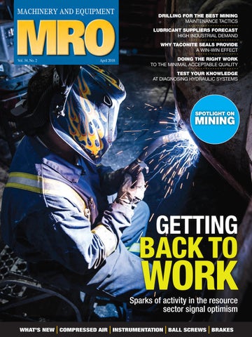
GETTING
BACK TO
WORK
Sparks of activity in the resource sector signal optimism WHAT’S NEW COMPRESSED AIR INSTRUMENTATION BALL SCREWS BRAKES