5 minute read
Riyadh: Case Study 1


CASE STUDY 1. KFC Outlet.
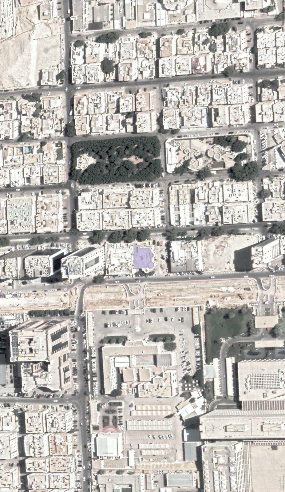
Fig 3.1.1 Shown highlighted is an abandoned KFC outlet. 8117 King Abdul Aziz Rd, Ad Dhubbat Riyadh 12623 3912
Advertisement
SITE ANALYSIS
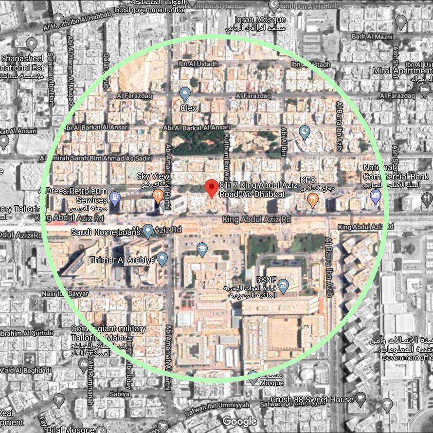
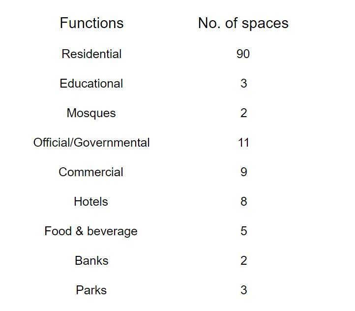
Fig 3.1.2 Shown is the ¼ mile radius Table 3.1.1 Showing the distribution of amenities within a circle around the site and what land 5 minute walk of the site. uses/amenities are available within a 5 minute walk.
Shown above are the amenities as present today. However, for the future TOD integration, the specific zone of the Metro that this is located on must be found, the building itself must be analysed as well, and then decisions must be made accordingly.
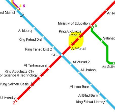
Fig 3.1.3 The figure above shows that the site is located on line 2, midway of the line’s intersections with lines 1 and 5.[82] This particular location is called the Activity Center in the Riyadh Metro.[83]
Referring to the above figure, it can be seen that this zone has to be extraordinarily developed, being a hub/crosswalk of different station lines.
According to the Executive Summary of the TOD that was issued by the Alriyadh Development Authority, structures should host retail, community services, hospitals, commercial offices, employment, attractions and other facilities should be provided.
As such, the issue that we are faced with now, is regarding what kind of program on this site could be ideal for this neighborhood/add diversity of functions.
In order to answer this, the building itself will be seen, to be able to understand the structure at least minimally, before making decisions about what it could possibly host.
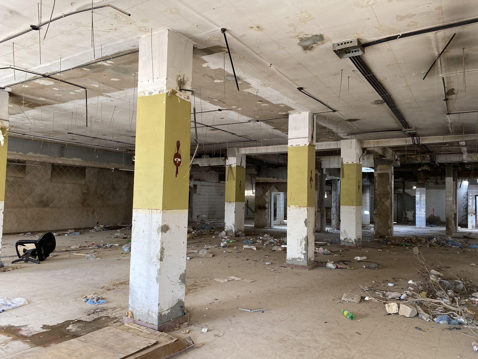
Fig 3.1.4 Facade of the building. Fig 3.1.5 Column spans.
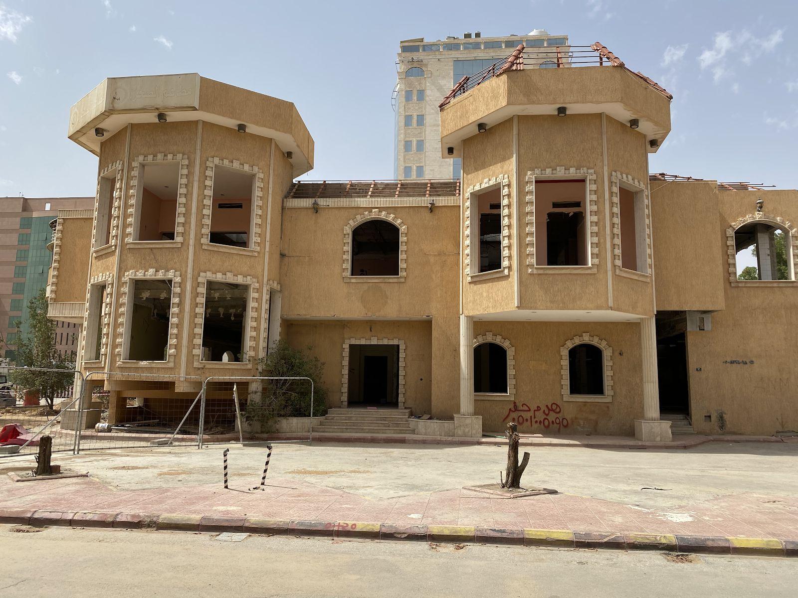
The building is made up of 5 levels, spread across the ground and first floor. The main floor slab levels are 4m apart.
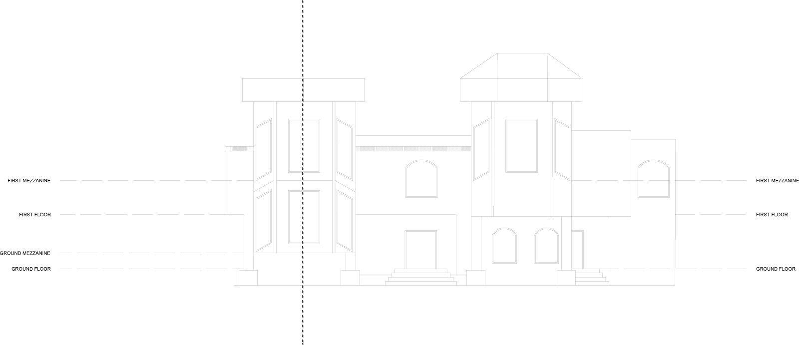
Fig 3.1.6 This image shows the elevation of the building with the different levels, as well as a line through the left tower to show where the section will cut through. The mezzanine of the ground floor is only present on the left tower, so that is where we will cut through.
Fig 3.1.7 This image shows the section with different levels.
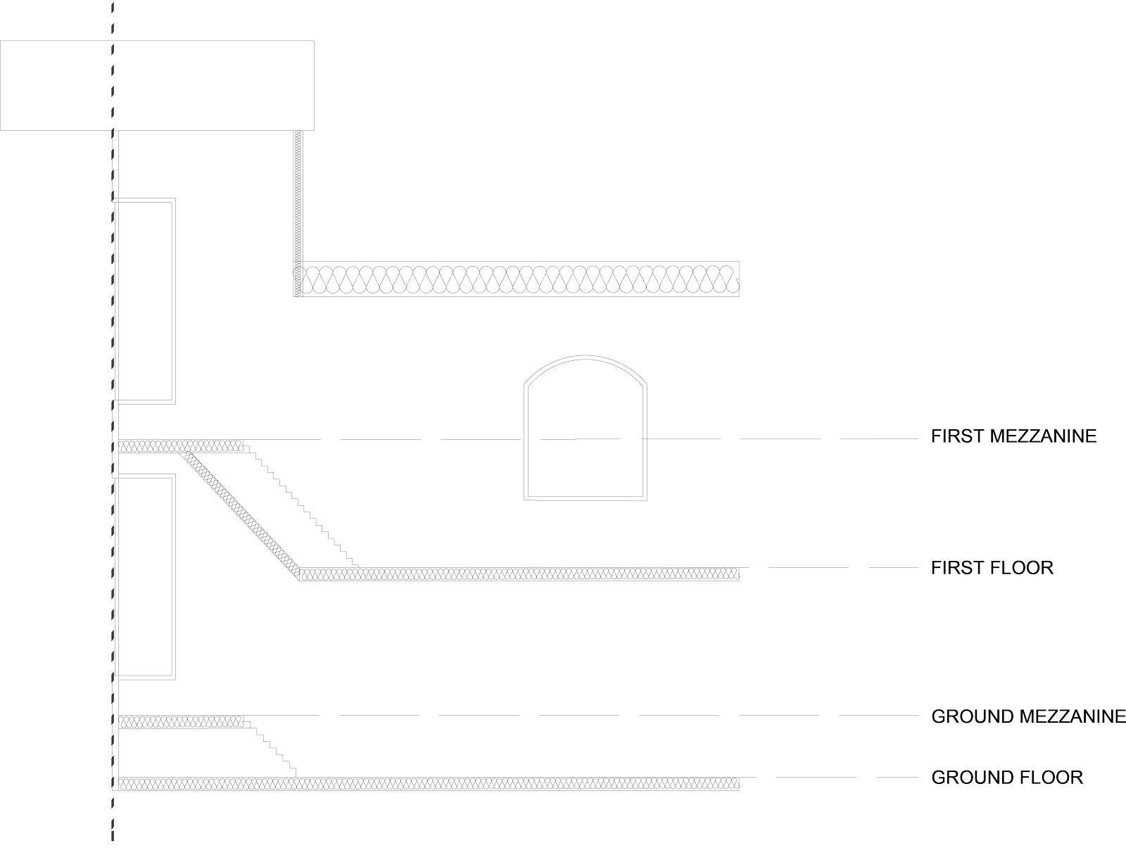
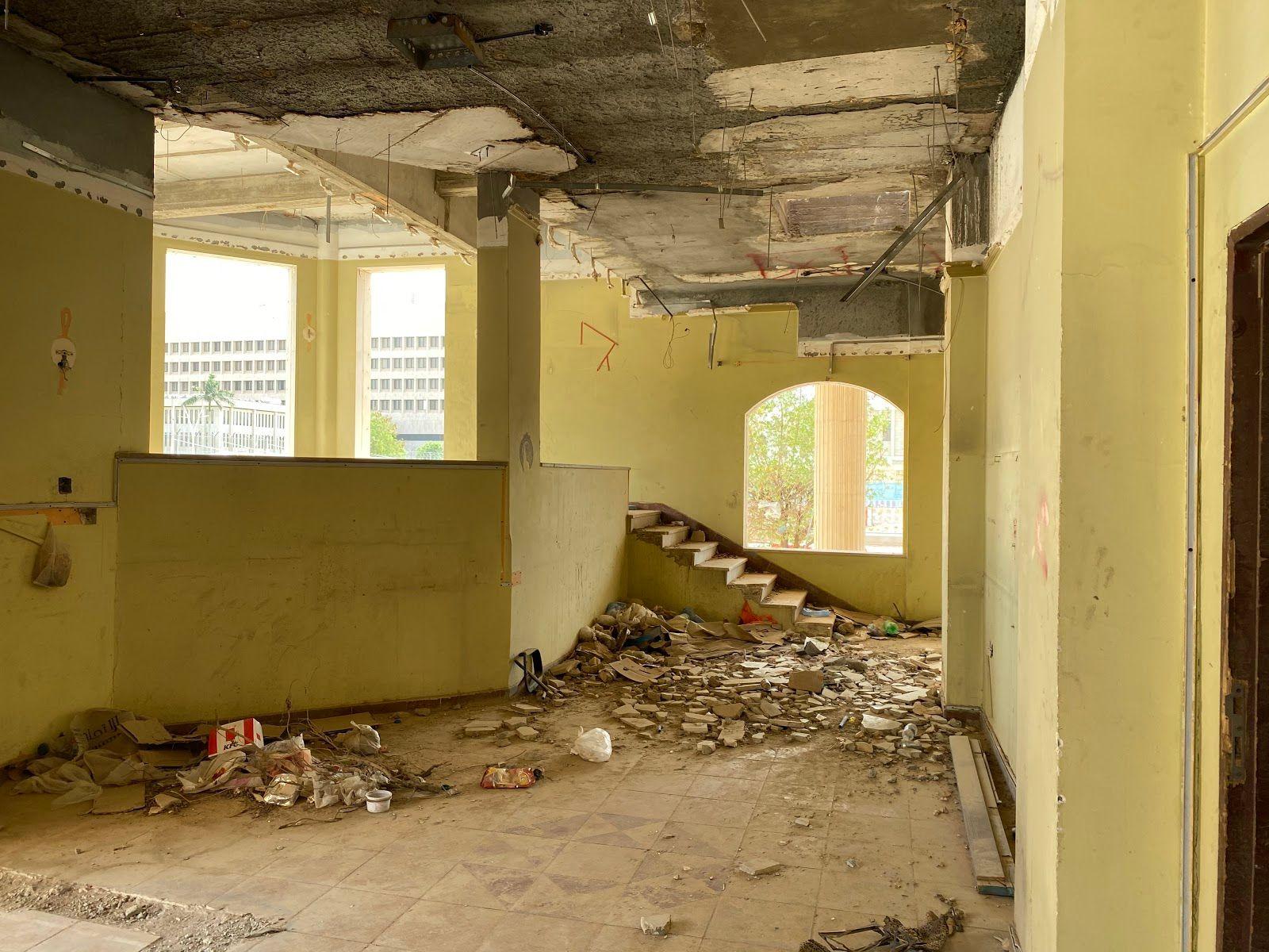
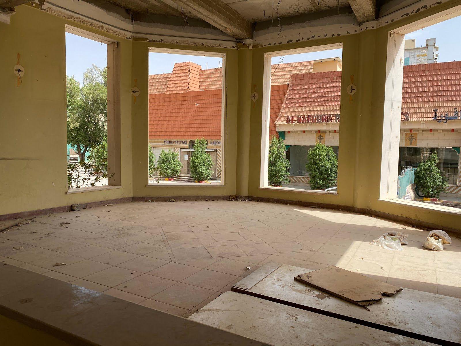
Fig 3.1.8 The two images above show the raised area - the approach and ascent.
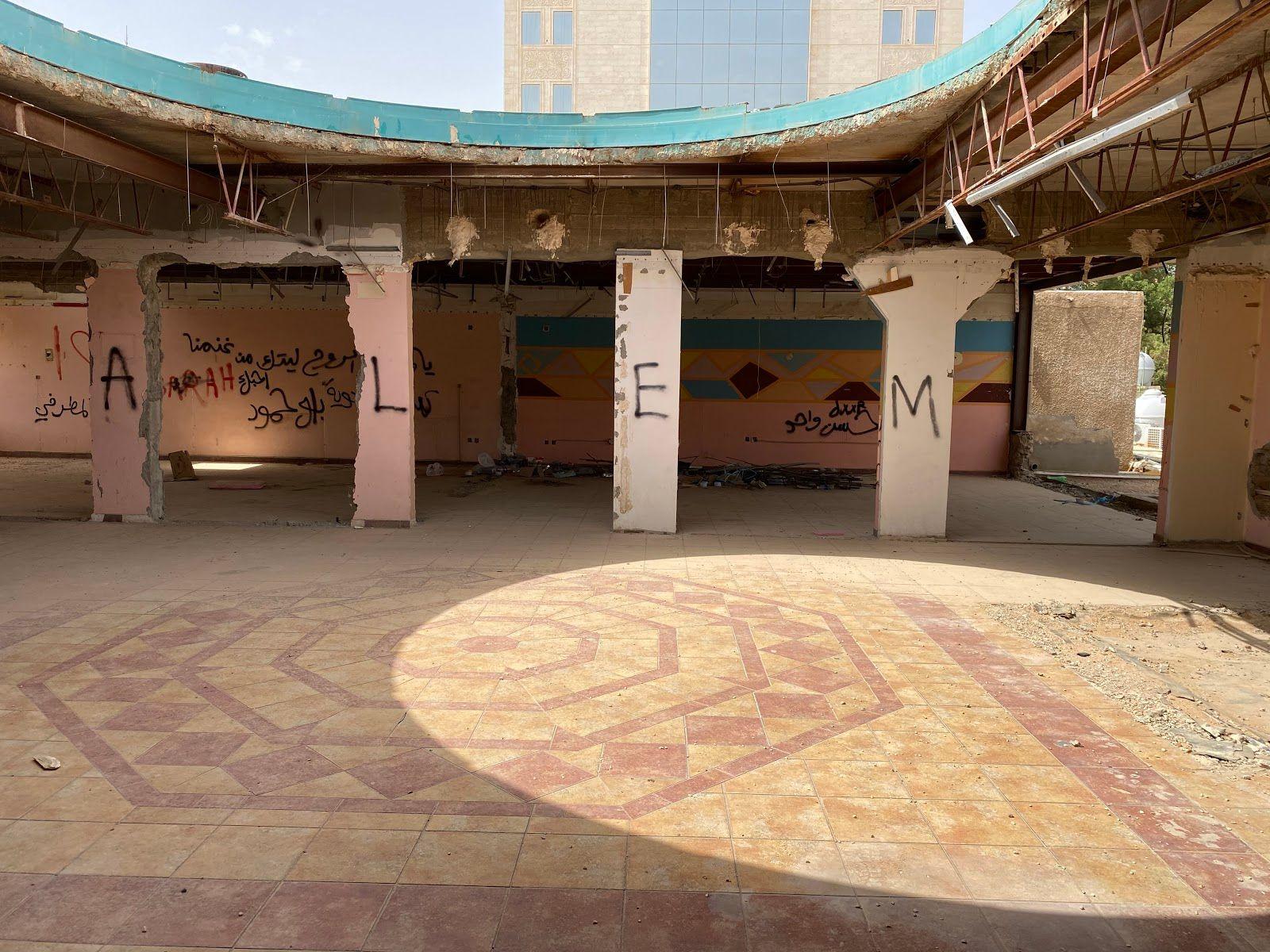
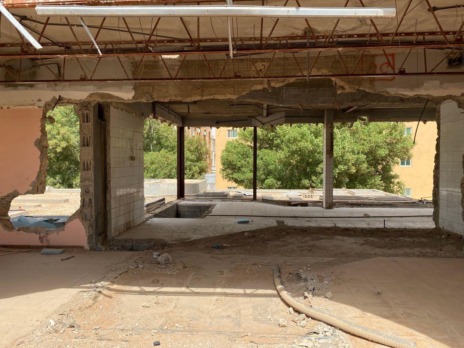
Fig 3.1.9 The image above shows the connection of what used to be the dome, and colonnade.
Fig 3.1.10 The images above show different fenestration frames and opportunities to create views.
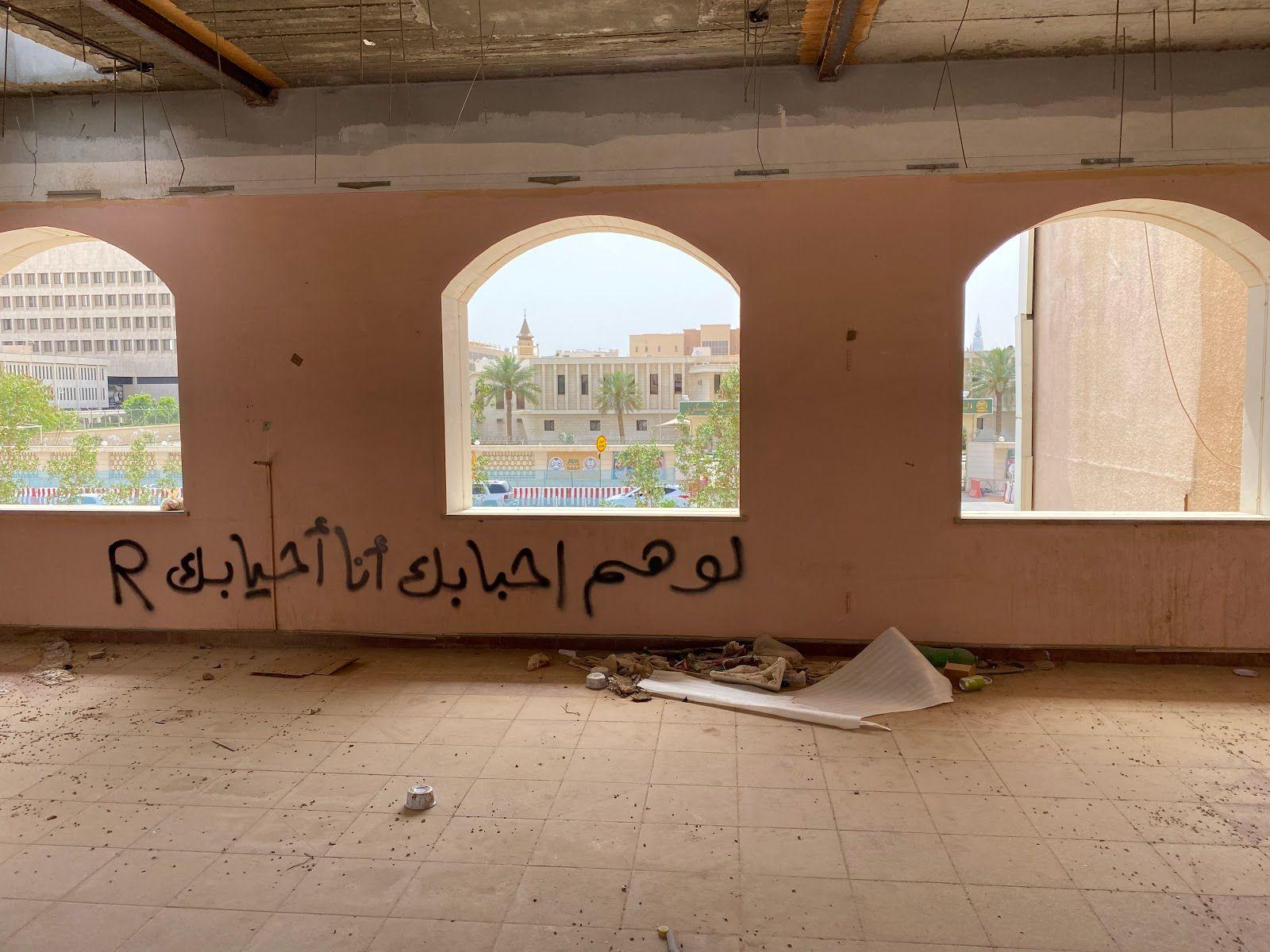
Upon studying the surrounding functions, and analysing both what is required of the TOD and what the building itself could be used for, it was concluded that there are not many children-specific areas around, apart from the parks (which are not directly adjacent to the Metro line). There are also no bookstores or libraries, or a community space where people of all ages could mingle. Therefore, this is what the building will be used as.
On the ground floor, there can be an indoor play area for children to the left, with book cafes lined against the right side. In a pocket on the left will be a bookstore selling both used and new books. The center would simply be an area for circulation, to reach the far back where the bathrooms are, and to appreciate the atrium above.
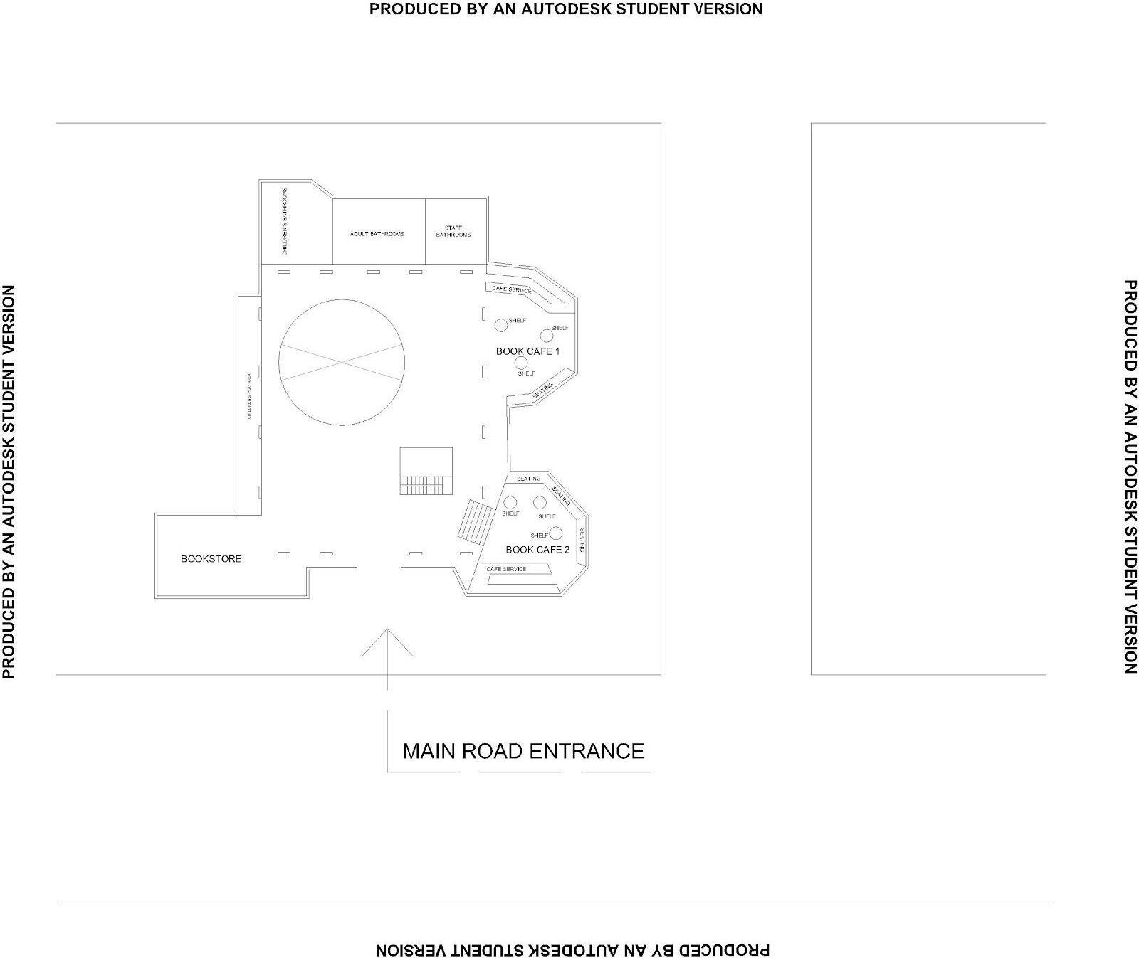
Fig 3.1.11 The reused ground floor schematic sketch. The original columns stay in place, as well as the bathroom area at the back. The circle shows where the atrium would be. The stairs also stay in place.
The first floor, on the other hand, would be a retail and lounge area, where light can filter through an atrium, balcony, curtain wall, and skylight. The retail will consist of traditional crafts shops and gifts shops, in ideal lighting, given their positions by the windows, while the lounge area is shaded by the colonnade, cooler and relaxed.
Fig 3.1.12 The reused first floor schematic sketch.


Fig 3.1.11 The rendering above shows the children’s area on the ground floor.
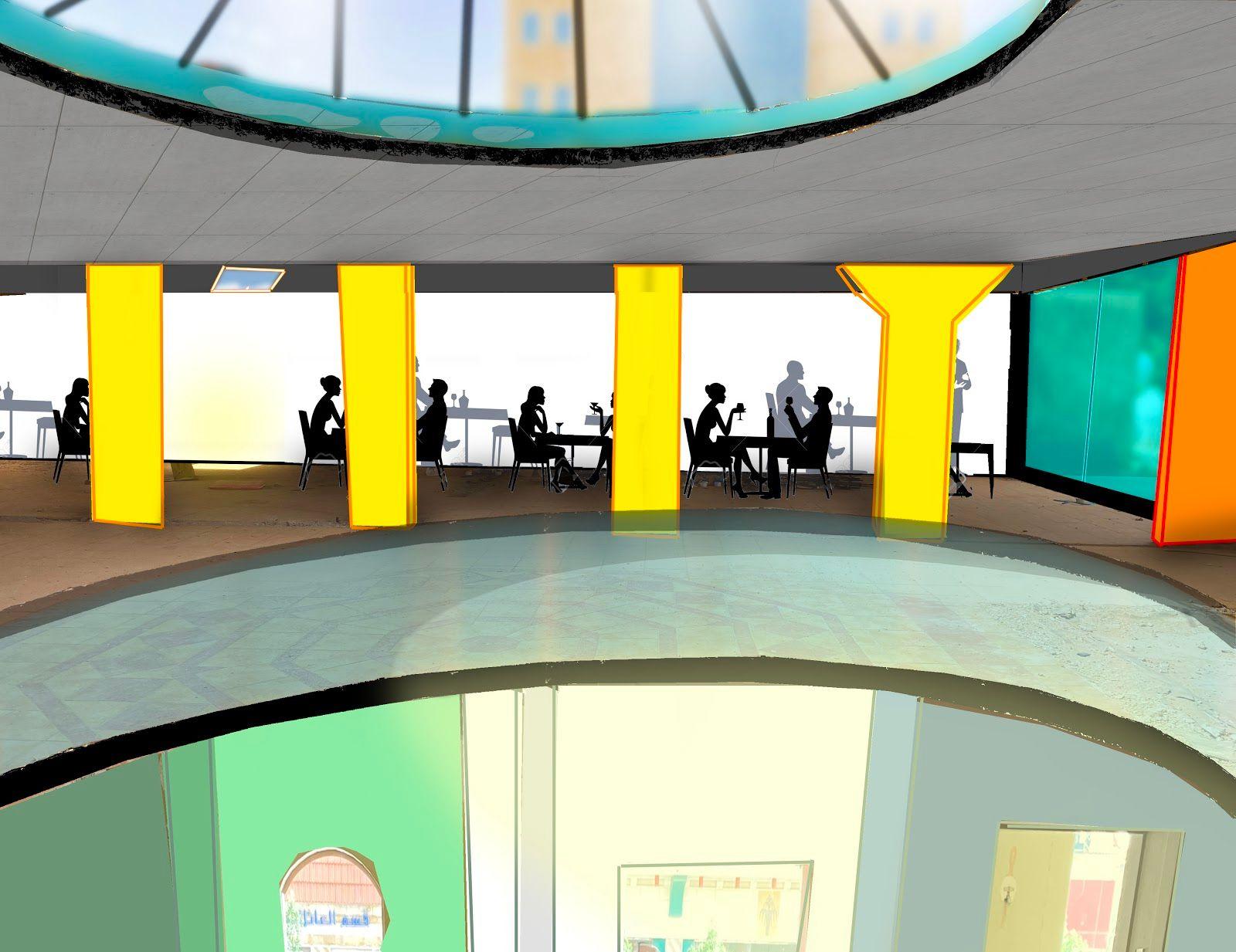
Fig 3.1.12 The image above shows the atrium from the first floor view.
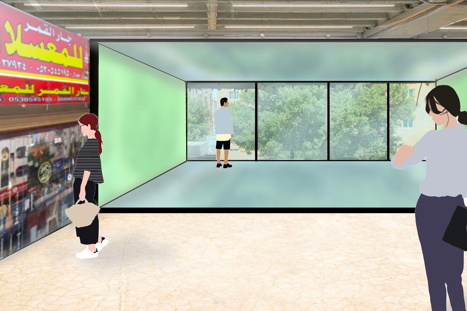
Fig 3.1.13 The image above shows improved glazing from Fig 3.1.10.
Since the openings already provided by the original structure is sufficient for the placement of activities and their daylight requirements, no more windows will be added. The atrium was created only to add dynamism to the building, and this was a feasible move, since the concrete is reinforced and no columns were affected.
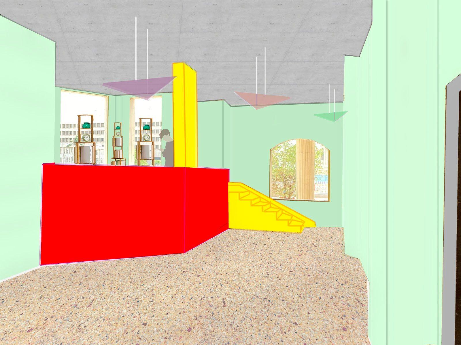
Fig 3.1.14 The image above shows a view towards one of the book cafes.
The visit to the building showed that most of the electrical wiring and plumbing systems were still intact, which means the only upgrading required would be choosing LED light fixtures, and toilet fixtures. For the HVAC, the piping was still visible, as well as the roof of the building. This means aircon units need to be installed, but minimal work will be needed to do so.


