International Research Journal of Engineering and Technology (IRJET) e-ISSN: 2395-0056
Volume: 12 Issue: 03 | Mar 2025 www.irjet.net p-ISSN: 2395-0072


International Research Journal of Engineering and Technology (IRJET) e-ISSN: 2395-0056
Volume: 12 Issue: 03 | Mar 2025 www.irjet.net p-ISSN: 2395-0072
Hashim Naseer1 , Anjana M.S2, Afnan Sackir3, Sufil K Basheer4, Biby Aleyas5
1Bachelor of Technology in Civil Engineering, Ilahia College of Engineering and Technology, Kerala, India
2Bachelor of Technology in Civil Engineering, Ilahia College of Engineering and Technology, Kerala, India
3Bachelor of Technology in Civil Engineering, Ilahia College of Engineering and Technology, Kerala, India
4Bachelor of Technology in Civil Engineering, Ilahia College of Engineering and Technology, Kerala, India
5Assistant professor, Department of Civil Engineering, Ilahia College of Engineering and Technology, Kerala, India
Abstract - Land surveying is a cornerstoneofinfrastructure development, construction, and land management, but traditional methods often come with challenges like lengthy fieldwork, time-consuming processes, and the risk of human error. To address these issues, this study dives into the potential of Differential Global Positioning System (DGPS) technology as a game-changer for landsurveying.DGPSoffers highly accurate geospatial data, slashing errors and speeding up data collection compared to older methods. In this research, a DGPS device was used to survey a specific plot of land. The data collected was then processed to create a detailed site plan using AutoCAD, bringing the survey to life in a digital format. To further understand the terrain, a contour map of the plot was generated using Esurvey CAD software. This map not only provided a clear visual of the land’s elevation changes but also helped in calculating earthwork needed for leveling the site. The findings highlight how DGPSbased surveying can revolutionize the field, offering a faster, more accurate, and efficient way to gather and process land data. This makes it an invaluable tool for engineers, construction teams, and land managers,streamliningprojects and reducing the margin for error. By embracing this technology, the future of land surveying looks not only more precise but also more manageable and less labor-intensive.
Key Words: DGPS, Land Surveying, AutoCAD, Esurvey CAD, Contour Mapping, Earthwork Calculation, Accuracy, Speed, Efficiency
Land surveying is a vital part of civil engineering, construction,andlanddevelopment,providingthecritical geospatial data needed for planning sites and calculating earthwork.Traditionalmethods,likeusingatotalstationor leveling equipment, often demand a lotof timeandeffort, and they’re not immune to human error. To tackle these challenges,newertechnologieslike the Differential Global Positioning System (DGPS) have become increasingly popular.
DGPSisahigh-precisiontoolthatbuildsonstandardGPSby using correction signals from reference stations, boosting
accuracy and reliability. This makes data collection faster and more dependable, streamlining the entire surveying process.Inthisstudy,aDGPSdevicewasusedtosurveya specificplotofland.Thedatagatheredwasthenprocessed tocreateadetailedsiteplanusingAutoCAD,andacontour map was generated with Esurvey CAD software to show elevationchangesandhelpwithearthworkcalculations.
ThemaingoalofthisresearchistoshowhowDGPS-based surveying can improve accuracy, save time, and make the wholeprocesssimplerandmoreuser-friendly.Bycombining DGPS technology with advanced software for data processing, this approach offers a smarter, more efficient way to measure land and analyze terrain, especially for projects that need precise earthwork planning. It’s a step forwardinmakingsurveyingmoreaccessibleandeffective forprofessionalsinthefield.
Accuratelandsurveyingisacornerstoneofengineeringand constructionprojects,providingthevitaldataneededforsite planning, earthwork calculations, and infrastructure development.Traditionalmethods,likeusingtotalstationsor leveling instruments, often come with their own set of challenges they’re time-consuming, labor-intensive, and pronetohumanerror.Theseissuescanleadtoinaccuracies inmeasurements,whichnotonlyslowdownprojectsbutalso driveupcosts.
To tackle these problems, the use of Differential Global PositioningSystem(DGPS)technologyhasbecomeagamechangerinlandsurveying.DGPStakesstandardGPStothe next level by using real-time corrections from reference stations,deliveringmuchmoreprecisepositioningdata.This notonlybooststhereliabilityofsurveymeasurementsbut alsocutsdownsignificantlyonthetimespentinthefield.
Inthisstudy,DGPSwasusedtosurveyaspecificplotofland. Thedatacollectedwasthenprocessedtocreatea detailed siteplanusingAutoCAD.Tobetterunderstandtheterrain,a contourmapwasalsogeneratedusingEsurveyCADsoftware, helpingtovisualizeelevationchangesandmakingearthwork calculationseasier.Thisprojectwasbornoutofthegrowing

International Research Journal of Engineering and Technology (IRJET) e-ISSN: 2395-0056
need for faster, more accurate, and efficient surveying methodsthatreduceerrorsandsimplifyprojectplanning.By combiningDGPSwithadvancedsoftwaretools,thisapproach offers a modern, practical solution for land measurement, making it especially valuable for engineering and construction projects. It’s a step toward making surveying moreprecise,efficient,andaccessibleforprofessionalsinthe field.

3.
Tomakelandsurveyingmoreaccurateandreliable
Tosavetimeandworksmarter
Tomakesurveyingeasierandmoreuser-friendly
Tocreateaclearanddetailedsiteplan
To map out the terrain and understand elevation changes
Tohelpplananddesignearthworkwithconfidence
ToshowhowDGPS-basedsurveyingcanbeagamechanger
4.1 Surveying with DGPS
4.1.1 Description of EFIX F4 and F7 DGPS Instrument
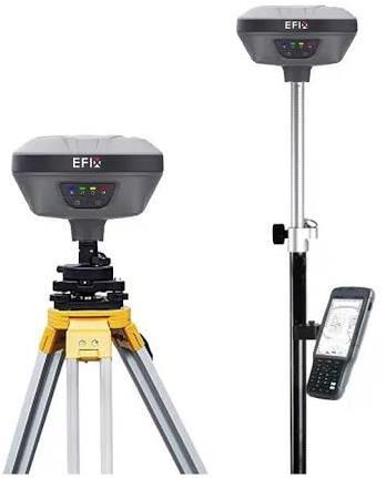
TheEFIXF4andF7arecutting-edgeGNSS(GlobalNavigation Satellite System) receivers built to deliver high-precision resultsforlandsurveyingtasks.Thesedevicesaredesigned toworkseamlesslywithmultiplesatellitesystems,including GPS, GLONASS, Galileo, and BeiDou, ensuring reliable and accurate positioning data even in tough environmentslike dense urban areas or remote locations. Whether you're working on a construction site, mapping out terrain, or planninginfrastructure,thesereceiversarebuilttokeepup withyourneeds.
Oneofthestandoutfeaturesofthesemodelsistheirabilityto connectwithmultiplesatelliteconstellations.Theycantrack signals from GPS (L1, L2, L5), Galileo (E1, E5a, E5b), and BeiDou(B1,B2,B3),whichmeansyou’llalwayshavestrong satellitevisibilityandpinpointaccuracy,nomatterwhereyou are. With an impressive 824 channels, they can handle multiplesatellitesignalsatonce,ensuringyourdataisboth reliableandprecise.
Another game-changing feature is the built-in Inertial MeasurementUnit(IMU),whichallowsfortiltcompensation of up to 60 degrees. This means you don’t have to worry aboutkeepingthepoleperfectlyverticalevenifit’sslightly tilted,you’llstillgetaccuratereadings.Plus,thesedevicesare built to last. With an IP67 rating, they’re dustproof and waterproof,makingthemperfectfortoughfieldconditions, whetheryou’reworkingintherainoronadustyconstruction site. And despite their rugged design, they’re surprisingly lightweighttheEFIXF4,forexample,weighsjust0.77kg,so youcancarryitaroundalldaywithoutfeelingweigheddown.

Google.com)
4.1.2 Setup Process and Data Collection Technique
Step 1 - Equipment Preparation
Before heading out, make sure everything is ready to go. StartbycheckingtheEFIXF4/F7receiver,ensureit’sfully chargedandfunctioningproperly.Dependingonyoursurvey needs, mount the receiver on either astable tripodor asurvey polefor mobility. Don’t forget to attach theUHF
Volume: 12 Issue: 03 | Mar 2025 www.irjet.net p-ISSN: 2395-0072 © 2025, IRJET | Impact Factor value: 8.315 |

Volume: 12 Issue: 03 | Mar 2025 www.irjet.net
antennato the receiver, this is crucial for smooth communicationbetweenthebaseandroverunits.
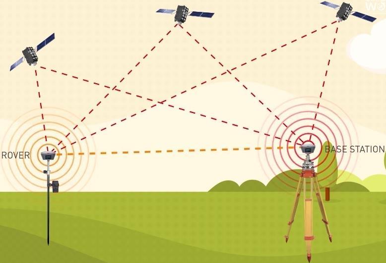
Thebasestationisyouranchorpoint,soit’simportanttoset it up correctly. Begin by securely mounting the EFIX F4 receiver onatripodataknownreferencepoint.Makesure thesetupisstableandthereceiverisperfectlylevel.Turnon thedevicebypressingandholdingthepowerbuttonuntil the indicators light up. Next, use the field software to configure the receiver to operate in base mode. Set the communicationparameters,likefrequencyandprotocol,to matchtheroverunit.Thisensuresseamlesscommunication betweenthetwodevices.
The rover is your mobile unit, so it needs to be ready for action. Attach the EFIX F7 receiver to a survey pole and doublecheckthatthe UHF antenna isproperlyconnected. Power it on by pressing the power button until the indicatorscometolife.Then,openthefieldsoftwareonyour controllerdevice(likeatabletorhandheldcomputer)and connect it to the rover receiver. Configure the rover to operate in rover mode, making sure the communication settings align with the base station. This step ensures everythingissyncedandreadyfordatacollection.
Nowcomestheexcitingpart,collectingthedataFirst,wait for the rover receiver to achieve a fixed solution, which means it’s locked onto the satellite signals and ready to provide reliable positioning data. Once that’s done, start surveyingbyusingthefieldsoftwaretocollectdatapoints. Thanks to the IMU integration, you don’t have to worry aboutkeepingthepoleperfectlyvertical,itcantiltupto60 degreesandstilldeliveraccurateresults.Asyoucollectdata, it’sstoredinternallyonthedevice.Later,youcanexportit for post-processing or use it directly in software like AutoCAD or Esurvey CAD tocreatedetailedsiteplans orcontourmaps.


Volume: 12 Issue: 03 | Mar 2025 www.irjet.net
35
36
Onceyou’vecollectedyourDGPSsurveydata,thenextstepis to turn it into a clear and professional site plan using AutoCAD.Here’sa step-by-stepguidetohelpyouthrough theprocess:
Start by connecting your DGPS device to a computer and downloading the collected data. Save it in a CSV (CommaSeparatedValues)or TXT formatforeasyprocessing.Make sure the data includes all the essential details like Point ID, Easting (X), Northing (Y), Elevation (Z), and Description.Thisinformationisthefoundationofyour site plan, so double-check that everything is accurate and complete.
LaunchAutoCADandcreateanewdrawingfile.Beforeyou start, set the correct units to match your survey data. Type "UNITS" in the command bar and choose the appropriateunit(metersorfeet).Ifyourprojectrequiresa specificcoordinatesystem,setthatupnowaswell.

Volume: 12 Issue: 03 | Mar 2025 www.irjet.net
If your DGPS data is in CSV format, you can use the "DATAEXTRACTION" command or a custom script to import it into AutoCAD. Alternatively, you can use the "IMPORT" tool or the "Survey Database" feature (available in some versions of AutoCAD) to bring in the surveydatainbulk.Thisstepsavestimeandensuresallyour pointsareaccuratelyplacedinthedrawing.
Now it’s time to connect the dots, use the “PLINE” or “POLYGON” to link boundary points based on their descriptions. Draw property lines, roads, and other key featuresusingthesurveydataasyourguide.Thisstephelps youvisualizethelayoutofthesite.
Step
Tomakeyoursiteplaneasytoread,labeleachsurveypoint withit’s Point ID or Elevation.Usethe “TEXT” or “MTEXT” commandtoaddtheselabels.Thisway,anyonelookingat theplancanquicklyidentifyspecificpointsandtheirdetails.
Step 6 -Draw Existing Features (Buildings, Roads, Utilities, etc.)
Next,addexistingstructuresandfeaturestotheplan.Use commands like "LINE," "ARC," and "CIRCLE" to represent buildings, roads, utilities, and other important elements. Organize these features into separate layers to keep your drawingcleanandeasytonavigate.
Openthe Layer Manager (type "LA" inthecommandbar) andassigndifferentlayersforboundaries,text,andsurvey points.Usecoloursandlinetypestodifferentiatebetween elements. For example, you might use a bold line for propertyboundariesandadashedlineforutilities.Thisstep makesyoursiteplanmorevisuallyappealingandeasierto understand.
To wrap up, fine-tune your site plan for clarity and professionalism.Adjust line weights and colors tohighlight key elements and improve readability. Once you’re happy withtheresult,savethefilein DWG format forfutureedits orexportitasa PDF forsharinganddocumentation.


A contour map is a powerful tool that shows elevation changes across a site, making it essential for tasks like earthwork calculations, drainage planning, and terrain analysis.EsurveyCADisauser-friendlysoftwaredesigned specifically for creating contour maps from survey data. Here’sastep-by-stepguidetohelpyougenerateacontour mapusingDGPSdata:
Step 1 - Export DGPS Data
Start by connecting your DGPS device to a computer and extractingthesurveyeddata.SavethedatainCSV(CommaSeparated Values) orTXTformat, ensuring it includes columnsforPointID,X,Y,andZcoordinates.Thisdatawill serveasthefoundationforyourcontourmap.
Step 2 - Launch Esurvey CAD and Open a New Drawing
OpenEsurveyCAD,eitherasastandalonesoftwareorasa pluginwithinAutoCAD.Createanewdrawingfiletobegin workingonyourcontourmap.
Step 3 - Import Survey Data
Navigate to theContour Moduleand selectImport Points. Choose the CSV or TXT file containing your DGPS survey

International Research Journal of Engineering and Technology (IRJET) e-ISSN: 2395-0056
Volume: 12 Issue: 03 | Mar 2025 www.irjet.net p-ISSN: 2395-0072
pointsandclickOpen.Verifythatallthepointsaredisplayed correctlyonthescreen.
Step 4 - Define Contour Intervals
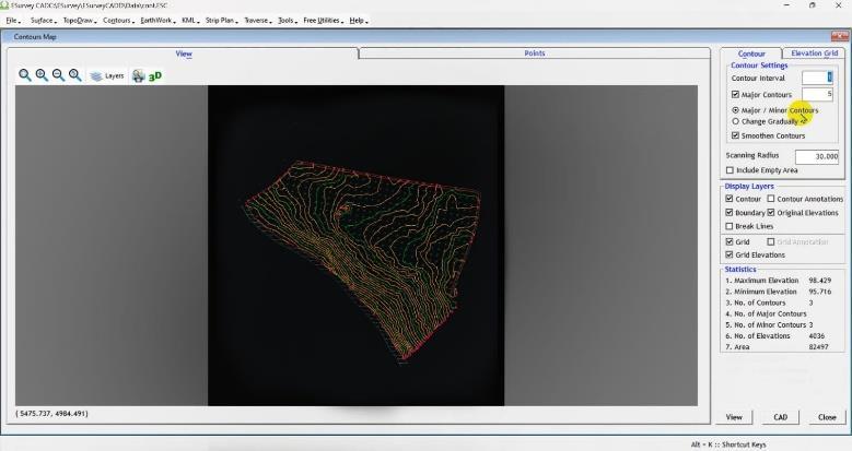
Setthecontourintervalbasedontheneedsofyourproject. For example, you might choose 0.5m for detailed work or 1m or 2m for larger sites. Enter the interval in the Contour Settings under Contour Interval
Step 5 - Create the Contour Surface
Click on Generate Contours to create a Triangulated Irregular Network (TIN Surface) fromthesurveypoints. Thesoftwarewillautomaticallyinterpolateelevationchanges andgeneratesmooth,accuratecontourlines.
Step 6 - Modify Contour Display (Optional)
Ifneeded,adjustthe smoothing settings torefinethecurves of the contour lines. You can also customize the line thickness and colors formajorandminorcontourstomake themapeasiertoread.
Step 7 - Labelling Contours
Use the Annotate → Label Contours tool to add elevation values to the contour lines. Adjust the font size and placement to ensure the labels are clear and readable.
Step 8 - Adding Boundary & Features
If you have additional data like site boundaries, roads, or waterbodies,youcanimportthemusing DXF or DWG files
Use tools like Polyline or Boundary Line to overlay these features onto the contour map, giving it more context and detail.
Step 9 - Save and Export the Contour Map
Once your contour map is complete, save the drawing in DWG (AutoCADformat)or DWT (EsurveyCADformat)for futureedits.Ifyouneedtosharethemaporincludeitina report,exportitasa PDF or JPEG file.

Whenitcomestolandsurveying,accuracy,time,andeffort are critical factors. The introduction of DGPS (Differential Global Positioning System) technology has brought significant improvements over traditional surveying methods. Here’s a quick comparison to highlight the differences:
Table -2: ComparisonofDGPSresultswithtraditional methods
Parameter Traditional Survey DGPS Survey
Accuracy(m) 0.5 0.02
TimeRequired(hrs) 10 4
HumanEffort High Low
As shown in the table, DGPS delivers a remarkable leap in accuracy,reducingerrorsfrom ±0.5meters tojust ±0.02 meters. This level of precision is especially valuable for projectswhereevensmallerrorscanleadtobigproblems.
Intermsof time,DGPScutsdownsurveyinghoursfrom 10 hours tojust 4 hours.Thismeansprojectscanmoveforward faster,savingbothtimeandresources.
Finally,the human effort requiredissignificantlyreduced. Traditionalmethodsofteninvolvelabor-intensiveprocesses, while DGPS simplifies the workflow, making it easier for surveyorstocollectdataefficiently.

Fig -7:AutoCAD-generateddrawingofthesurveyedplot


1
2
4
5
6
7
9
20
The use of DGPS-based land surveying has proven to be a game-changer, bringing significant improvements in accuracy,efficiency,andoveralleaseofsurveyingoperations. Byleveragingadvancedtoolslikethe EFIX F4 and F7 DGPS instruments, we were able to collect highly precise geospatial data, drastically reducing the errors often associatedwithtraditionalsurveyingmethods.
The AutoCAD-based site plan providedaclearanddetailed representationofthesurveyedplot,ensuringaccurateland assessmentandeffectiveplanning.Meanwhile,the Esurvey CAD-generated contourmap offeredavisualunderstanding of terrain elevations, which is essential for earthwork calculationslikecuttingandfilling.
Thisintegratedapproachnotonlyspeedupdatacollection but also simplified post-processing, making the entire
surveying process more efficient and reliable. The project underscores the value of embracing modern surveying technologiestooptimizelanddevelopmentprojects,reduce human errors, and support better decision-making in civil engineeringapplications.
[1] AlabiA.O,AlademomiA.S,SalamiT.J,OkutuboA.Dand Oyedokun W.R, “Accuracy assessment of established controlsforprecisepositioningusingDGPSandCORS,” Science,vol.8,Mar,2024pp,0.1-12doi:10.36263/nijest. 2024.01.01.
[2] Ammar jasim dakhil, Mustafa shareef, and Ihsan Qasim“AssessmentofpositioningaccuracyusingDGPS inIraqisurveywork,”tqujes,Vol11.2,Apr2021ppdoi: 10.31663/tqujes.11.2.401.
[3] Debjyotighosh,Ashvinikumar,AbhishekkumarYadav, Sureshkannaujiya and Pareshnath singha roy“surface deformation monitoring of Raniganj coalfield, India, using advanced InSAR and DGPS,” Geomatics, Nat. Hazards Risk, vol 15,Jul pp doi: 10.1080/19475705. 2024.2375546
[4] Didigwu, and Augustus Ugonna Sunday“Comparative study of differential global positioning system (DGPS) and conventional survey methods of coordinates determination,” arejoen ,vol4(I),Mar2021 pp doi: 10.36265/arejoen.2021.010110.