International Research Journal of Engineering and Technology (IRJET) e-ISSN: 2395-0056
Volume: 12 Issue: 04 | Apr 2025 www.irjet.net p-ISSN: 2395-0072
DESIGN AND ANALYIS OF FLOORING SYSTEM AND FOUNDATION USING CSI SAFE SOFTWARE.
Aniket Patale1 , Ramzan Shaikh2 , Rehan Shaikh3 , Mrs. Shubhra Dhamande4
1Department of civil engineering, New Horizon Institute of Technology & Management, Thane, Maharashtra, India
2Department of civil engineering, New Horizon Institute of Technology & Management, Thane, Maharashtra, India
3Department of civil engineering, New Horizon Institute of Technology & Management, Thane, Maharashtra, India
4Department of civil engineering, New Horizon Institute of Technology & Management, Thane, Maharashtra, India
ABSTRACT
This study explores the application of CSI SAFE, a sophisticated software tool for foundation design, emphasizing its capabilitiesinanalyzinganddesigningvariousfoundationtypes.Theresearchhighlightstheintegrationofloadanalysis, soil-structure interaction, and support conditions, showcasing how SAFE streamlines the design process through its user-friendly interface and robust calculation algorithms. Case studies demonstrate the effectiveness of SAFE in optimizing foundation performance while ensuring compliance with industry standards. By utilizing SAFE, engineers can enhance accuracy, reducedesigntime, and improveoverallproject efficiency, ultimately leadingto safer and more cost-effectivefoundationsolutions.ThefindingssuggestthatadoptingadvancedsoftwaretoolslikeCSISAFEisessential formoderncivilengineeringpractices,particularlyincomplexprojectswhereprecisionandreliabilityaremostcrucial.
Keywords: SoilPressure,Deflection,PunchingShear,SafeDesign,Software.
1. INTRODUCTION
Seismic Design and Analysis of Multi-Storey Building Using Etabs and CSI Safe Software Play a Critical Role Ensuring the Structural Integrity and Safety of Structures Located in Different Seismic Zones. In This Comparative Analysis, We Will Design and Analysis of Building and Its Foundation in Seismic Zone ii and Zone v of INDIA, Using ETABS And CSI SAFE Software. CSISAFEIs WidelyUsefor Foundation Design and Analysis, Provides Engineers with Powerful Tools for Modelling, Analysing and Designing BuildingsSubjected toSeismicForces.TheUse ofCSISAFE Software in Both Seismic, Zone ii and Seismic Zone v Allows Engineers to Conduct Comprehensive Structural AnalysisandDesign,
Considering Factors Such as Seismic Load Combinations, Material Property and Geometric Constraints. CSI SAFE Provides the Necessary Tools for Modelling, Analysing and DesigningofFoundation,TheirPerformanceUnderSeismic Loads and Ensuring Compliance with Local Building and RegulationsSpecifictoEachSeismicZones.
The comparative analysis will delve into specifics of using CSI SAFE software to design reinforced concrete slabs and foundations in Seismic Zone II and Seismic Zone V, highlightingthesoftware'scapabilities.
1.1 EARTHQUAKE
Earthquake Can Be Understood as Earth-Surface Shaking Because Of Energy Which Is Suddenly Released by Reason
of Earth's Movement. This Earth's Movement Is Consequence of Plates Are Termed as Tectonic-Plates. The Crustofthe Earth Is Surrounded by Large-Number of Very BigSizeBodiesCalledTectonic-Plates,TheyAreConstantly Under Motion with Respect To One Another, Due to Their UnexpectedCollisionWithOneAnother-LeadingtoRelease ofEnergyWhichTravelsTowards theEarth -Surfaceinthe FormofWaves.
1.2 DIFFERENT SEISMIC ZONES IN INDIA
Indian Plate Is Responsible for Earthquakes of High Intensities and Frequency Reading Indian Subcontinent to CatastrophicEarthquakesAround53%IndianLandMassIs Vulnerable to Earthquakes, Based on Indian Geographical Statistics. According To Estimations Based on Report of WorldBankandUnitedNations,around200millionIndian Population to Be Affected from Storms and Earthquakes Around2050.AccordingToLatestDesignPracticeCode(Is: 1893:Part-1:2016),India Is Dividedinto4ZonesBased on Seismicity Observed of Indian Land Mask This Zones Are Namely Zone II, III, Iv, V Which Covers Entire Country. BeforeThePresentCodeThisDivisionsofZonesIsofSTo6 Types for Entire Country Which Is Now Reduce Two Only Four Ranging Between Zone V To Zone II Associated with HighesttoLowestSeismicityRespectively.
Zone II: -
This Zone Attracts Less Intensities of Earthquakes and Classified Under Low Damage Risk Zone, As Per Is Code Assigned Factor Of 0.10 As Only 10% Of Gravitational

International Research Journal of Engineering and Technology (IRJET) e-ISSN: 2395-0056
Volume: 12 Issue: 04 | Apr 2025 www.irjet.net
Acceleration Is Experienced by Structure as Maximum HorizontalAcceleration.
Zone III: -
This Zone Classified as Moderate Damage Risk Zone with Factor Of 0.16 As Per Is Code. Regions Included Are Some PartsofHimalayasandKashmir,AndamanandNicobar.
Zone IV: -
ThisZoneAttributedwithHigh-RiskDamagewithFactorOf 0.24 As Per Is Code. The Zone Income Passes Gangetic Plains,NationalCapitalDelhi,State of JammuandKashmir, FaltanAreaofMaharashtra,NorthernRegions ofBiharand BorderofNepalandIndia.
Zone V: -
This Zones Attracts Earthquake of High Intensity with Highest Risk Involved Attributed with Very High-Risk Damaged. Zone Factor Indicates Effective Level of Earthquake I.E. For Zero Period Which Is Used for Designing of Earthquakes Resistance Structures by Structural Engineers. Earthquake Prone Areas Generally Consists of Trap and Basalt Rocks, Regions Under This Zones Are Kashmir and Himalayan Regions, North East States, Northern Areas of Bihar and Region of Gujrat State MainlyKutch.

3. METHODOLOGY
Create the Auto cad plan
Assign beam column, slabs.
Define Load Cases Using IS 456: 2000 And IS 1893-2016
Define shear wall and draw shear walls and define the pier labels for each wall
Check the model and run analysis is carried out.
Export Process File from Etabs to Safe Software for Foundation analysis and design
DefineMaterial andsection Properties(Mat SlabandStiff Column)Againin safefor foundation.
2395-0072
Create The Model In ETABS Define Material and section Properties.
Select slabs and assign live load, floor finish and roof live load for the terrace floor
Define zone factor, importance factor, response reduction factor.
Comparison of zone II and zone V Check results, conclusion.
Define soil subgrade property. ActivateLoad combination dataexported fromEtabs Draw Slab area and stiff column

International Research Journal of Engineering and Technology (IRJET) e-ISSN: 2395-0056
Volume: 12 Issue: 04 | Apr 2025 www.irjet.net p-ISSN: 2395-0072
SeismicZoneFactor 0.10,0.36
DesignStripsin XandY direction
Checkresults, conclusion.
4. SPECIFICATION OF BUILDING.
Checkthe modelandrun analysisis carriedout.
Comparisonof zoneIIand zoneVResults.
4.1 DEVELOPMENT OF PLAN IN AUTOCAD.

4.2 BUILDING PROPERTIES
PARTICULARS VALUES
Typesofbuilding Public
HeightofStructure(M) 30M
NumberofStories G+8
Heightofeachfloorin(M) 3.6M
GradeofConcreteUsed M25
SteelGradeUsed HYSD500
BeamDimension(mm) 300×400,600×800
ColumnDimension(mm) 500×500,800×800
ConcreteDensity 24KN/M
DensityofSteel 78.5KN/M
TypeofSoil Medium
ShearWallThickness(mm) 200 SlabThickness(mm) 125,175
5. MODEL GENERATES IN ETABS AND SAFE.


International Research Journal of Engineering and Technology (IRJET) e-ISSN: 2395-0056
Volume: 12 Issue: 04 | Apr 2025 www.irjet.net p-ISSN: 2395-0072


6: - Foundation Diagram.

-
6. RESULT AND DISCUSSION
For Zone ll
Fig 8: - Displacement Graph

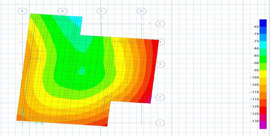
Fig 9: - Soil Pressure Graph


International Research Journal of Engineering and Technology (IRJET) e-ISSN: 2395-0056
Volume: 12 Issue: 04 | Apr 2025 www.irjet.net p-ISSN: 2395-0072
For Zone v
Fig 10: - Displacement Graph.

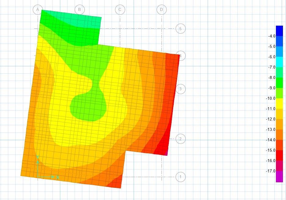
Fig 11: - Soil Pressure Graph.

of Soil. (Taken)
2
2
2
Permissible Limits: -
1) Settlement: - 50 mm for service condition as per IS Code 456:2000
2) SBC of Soil is 250 KN/M2 for Zone II and 450 KN/M2 for Zone V we Taken. According to Geotechnical Conditions.
ZONE II vs ZONE V
Zone II: -
BuildingDetails
Description
BuildingType G+8Storey
FloorHeight
AnalysisType
36m
Displacement and Soil Pressure
DisplacementRange -56mmto-108mm
SoilPressureRange -65KN/M2 TO130KN/M2
Foundationtype RaftFoundation.
Maximum Displacement Location Center of the structure (blue region)
Minimum Displacement Location Outeredges(redregion)
MaximumPressureLocation OuterEdges(RedRegion.)
MinimumPressureLocation CentralRegion(Green/Blue)
StructuralGrid
Contour Colour Representation
Possible Cause of Displacement
Labelled A to D and numbered1to5
Blue (Least displacement) to Red(Highestdisplacement)
Structural load, seismic activity,orwindforce
SoftwareUsed. ETABS,SAFE
Zone V: -
BuildingDetails
Description
BuildingType G+8Storey
FloorHeight 36m
AnalysisType Displacement and Soil Pressure.
DisplacementRange -4mmto-17mm
SoilPressureRange -180KN/M2 to-440KN/M2
Foundationtype RaftFoundation.
Maximum Displacement Location Center of the structure (blue region)
Minimum Displacement Location Outeredges(redregion)
MaximumPressureLocation OuterEdges(RedRegion.)
MinimumPressureLocation OuterEdges(RedRegion.)
StructuralGrid
Contour Colour Representation
Possible Cause of Displacement
Labelled A to D and numbered1to5
Blue (Least displacement) to Red(Highestdisplacement)
Structural load, seismic activity,orwindforce
SoftwareUsed ETABS,SAFE
|

International Research Journal of Engineering and Technology (IRJET) e-ISSN: 2395-0056
Volume: 12 Issue: 04 | Apr 2025 www.irjet.net p-ISSN: 2395-0072
CONCLUSION: -
Inthepresentwork,weaddressedthelimitationsof foundation of multi storey building using Mat/Raft
Foundation, the load sharing of raft results in gradualreductionofsoilsettlementbylargeamount ofareacoverbyraftfoundation.
By analysing multi-storey residential building foundationUsingSAFEsoftwareweconcludethat:
Analysis done by SAFE is very efficient and user friendly.
Software is developed for the analysis of raft using finite difference method, estimation of stiffness for soil.
Mat or raft foundations are adopted primarily to distributeloads froma structureovera largerarea, making them suitable for weak or compressible soils and heavy buildings, preventing excessive settlementandpotentialstructuralissues.
When You move to lower Seismic zones to Higher seismiczones,likeinourcase,ZoneIItoZoneV.
You need to Increase the Dimensions of Column, Beam, Slab Thickness and Bearing Capacity of soil (SBC) for Extreme Conditions, to achieve better stability,controlandSafety.
We have reduced the Settlement and Soil bearing pressurewithinthepermissiblelimitaspergivenin IS CODE 1904:1986 and Geo- technical considerationrespectively.
REFERENCE: -
1. Computers and Structures, Inc. (CSI). (2023). "SAFE: A Software Program for Structural and FoundationAnalysis."CSISAFEDocumentation
2. Bowles,J.E.(1996).FoundationAnalysisandDesign. McGraw-Hill. This textbook provides foundational concepts in foundation designthat cancomplement youruseofSAFE.
3. Abedini, M., & Ghasemi, F. (2017). "Application of CSI SAFE in Foundation Design for High-Rise Buildings." Journal of Construction Engineering and Management, 143(10), 04017075. This paper discusses practical applications of SAFE in realworldscenarios.
4. Dhanasekar, M., & Hossain, M. (2019). "Innovative Foundation Design Using CSI SAFE." Proceedings of
theInternationalConferenceonCivilandStructural Engineering. This conference paper highlights innovativetechniquesinfoundationdesign.
5. Zhang, Y., & Li, J. (2021). "Comparative Study of Foundation Design Methods Using CSI SAFE." International Journal of Civil Engineering and Technology, 12(3), 1234-1246. This case study compares traditional methods with those utilizing SAFE.
7.
BIOGRAPIES


ShubhraDhamande (Asst.Professor,DepartmentofCivil Engineering,NewHorizonInstituteof TechnologyandManagement,Maharashtra, India)
AniketPatale (B.EStudent,DepartmentofCivil Engineering,NewHorizonInstituteof TechnologyandManagement, Maharashtra,India)
RamzanShaikh (B.EStudent,DepartmentofCivil Engineering,NewHorizonInstituteof TechnologyandManagement, Maharashtra,India)
RehanShaikh (B.EStudent,DepartmentofCivil Engineering,NewHorizonInstituteof TechnologyandManagement,Maharashtra, India)
