International Research Journal of Engineering and Technology (IRJET) e-ISSN: 2395-0056
Volume: 12 Issue: 05 | May 2025 www.irjet.net p-ISSN: 2395-0072


International Research Journal of Engineering and Technology (IRJET) e-ISSN: 2395-0056
Volume: 12 Issue: 05 | May 2025 www.irjet.net p-ISSN: 2395-0072
Eshwaraprasad M1 , L. G ovindaraju2 ,
1Post graduate student, Dept. of Civil Engineering, UVCE College (University), Bangalore
2Professor, Dept. of Civil Engineering, UVCE college (University), Karnataka, India 560056
Abstract - Ground improvement is a crucial aspect of geotechnical engineering, enabling engineers to modify the natural state of the soil to meet project requirements. Slope stability is a critical concern, as unstable slopes can lead to catastrophic failures, resulting in widespread damage, loss of life, and economic disruption. Nailing and micropile is known as one of the most used methods of slope stabilization. This research study focuses on the analysis of a composite shoring system of micropiles and grouted nails for slope stabilization. A number of sections with varyingheightswereanalysedusing Plaxis 2D ultimate finite element software, considering MohrCoulomb model are used to define soil parameters. homogeneous, heterogeneous soil, and rock properties are considered. It is observed that the effects of shear force, bending moment, and displacement on the stability of the slope are examined, and the factor ofsafety(FOS)iscalculated for each section. The results demonstrate the effectiveness of the composite shoring system in improvingslopestability. This study provides a valuable contribution to the field of geotechnical engineering, offering insightsintothe design and analysis of composite micropile and grouted nail systems for slope stabilization.
Key Words: Slope Stability, Micropile, Grouted Nail, Composite System, Plaxis 2D, Mohr-Coulomb, Axial Force, Shear Force, Bending Moment, Displacement and Factor of Safety (FOS).
Deepexcavationisafundamentalaspectofgeotechnicaland civil engineering, involving the removal of substantial volumes of earth to create space for structures such as basements,undergroundparkinggarages,tunnels,subways, andothersubterraneanfacilities.Asurbanareascontinueto grow and the demand for vertical construction become increasingly common, particularly in densely populated citieswherespaceislimitedandinfrastructuremustextend belowgroundlevel.Theprocessofdeepexcavationrequires carefulplanning,design,andexecutionduetothesignificant geotechnical, structural, and safety challenges it presents. Unlikeshallowexcavations,whicharerelativelysimpleand typically require minimal support, deep excavations often encountercomplexsoilconditions,highgroundwaterlevels, and adjacent structures that can be sensitive to ground movement.
In modern geotechnical engineering, the demand for innovative,efficient,andadaptablefoundationsolutionshas ledtotheincreasinguseofmicropiles.Thesesmall-diameter, drilledandgroutedpileshaveprovenespeciallyvaluablein situations where conventional foundation methods are impracticalorinsufficient,particularlyinchallengingground conditions and confined construction environments. Micropiles are typically less than 300 mm (12 inches) in diameter and are constructed by drilling a borehole, insertingahigh-strengthsteelreinforcementelement,and fillingthevoidwithcement-basedgrout.Unliketraditional displacement piles, micropiles are installed with minimal disturbancetosurroundingsoilsandstructures.
Soil nailing isa cost-effective method for reinforcement of slopes and construction of retaining walls in a top-down manner. This method of soil reinforcement employs steel tendons which are grout or drilled into the soil to form a composite mass similar to a gravity wall. Soil nails are installedatananglerangingbetween10and20degreesto the horizontal and are most often in tension. It is the deformation of materials that are retained during the excavationprocessthatpassivelyappliestensilestresstothe soilnails.Thepurposeofsoilnailingiscommonlytosecure and support slopes and excavations where superstructure constructionsequentiallyoccursfromthetop.
Thestudyaimstoevaluatethestabilityandsafetyofdeep excavations,rangingfrom13mto21mindepth,subjectedto varyingsurchargeload.The excavationsaresupportedby compositeshoringsystemofMicropilingandNailing.Afinite element based numerical analysis geotechnical software PLAXIS 2D VERSION 24 is used for the numerical analysis purpose.Thesoilprofileisgeometricallymodelledandthe properties of the soil and other elements are created and assigned.Theanalysisinvolvesstagedconstruction,withthe factor of safety evaluated at each excavation stages. The objective of the study is investigating the effectiveness of thesesupportsystemsinmaintainingexcavationstabilityand identify potential failure mechanisms. The results of this studywillprovideinsightsintothedesignandperformance

International Research Journal of Engineering and Technology (IRJET) e-ISSN: 2395-0056
Volume: 12 Issue: 05 | May 2025 www.irjet.net
ofsoilnailingandmicropilingsystemsfordeepexcavations, contributingtothedevelopmentofmoreefficientandsafe excavationsupportsystems.
Table 1 Properties of Grouted nail system

Table 2 Properties of Micropile for composite system
Parameter
Poisson’s
Table 3 Material properties for facing
ByusingPlaxis2Dsoftwaretheresultsofstabilityofslope weresupportedbyacompositeshoringsystemintegrating bothmicropilingandsoilnailingtechniques.Thissystemwas designedtoretainthesurroundingsoilandpreventcollapses underbothstatic anddynamicloadingconditions.Various configurations were analysed, including with and without nails,andalterationsinnaillengthandspacing.Parameters suchas the properties of the micropile and nailingsystem werevariedtoassesstheireffectiveness.
3.1 STABILITY ANALYSIS OF SECTION – 1
The analysis is performed to evaluate the stability and deformationinvolvingatotalexcavationdepthof13.075m consistingofmultiplestagesataconstructionsite.
Table 4 soil properties
Material
Type
Mohrcoulomb
Unitweightofdrysoil, unsat kN/m3 18
Unitweightofsaturatedsoil, sat kN/m3 20
Stiffness,Eref kN/m2 20*103
Poisson’sratio, - 0.3
Thissectiondescribestheexaminationofinitialstabilityof slope without any shoring system. The analysis was performed using PLAXIS 2D software, C-Phi reduction methodiscariedouttodeterminethefactorofsafety(FOS).

Fromtheanalysisresults(Fig-2)itisseenthatthefactorof safetyis0.41.Thefactorofsafetyislessthantherequired value of 1.5, indicating that the slope is unsafe. Hence, a suitableshoringsystemisproposed.
The analysis has been carried out considering micropile system only to retain a vertical cut of 6 m with an embedmentdepthof3m.Themicropiledesignconsistsof using 220 mm diameter steel pipe with 8 mm thick. Two steel bars of Fe500 having diameter 25 mm are used as reinforcementsinthepipe.

International Research Journal of Engineering and Technology (IRJET) e-ISSN: 2395-0056
Volume: 12 Issue: 05 | May 2025 www.irjet.net p-ISSN: 2395-0072


Theanalysisresultsshowthatthefactorofsafetyis0.86and thehorizontaldisplacementofmicropileattopis197mm Additionally, the shear force and bending moment values obtainedfromtheanalysisarepresentedinTable
Table 5 Shear Force and Bending Moment values
Shearforce(kN/m)
The analysis indicates that the slope is not stable with micropiling alone, suggesting that the slope requires a compositeshoringsystem,suchasmicropileandsoilnailing toachievestability.
Inthiscaseuseofmicropileandsoilnailingwasnecessary becausethevariouscasesweredone withoutshoringand micropiling,butthesoilwasnotenoughtostabilisetheslope tocarrytheload. Thesoilnailsoflengthof9mwereused alongwithmicropile.


Fromtheanalysisresults,itisevidentthatthesystemissafe. Figure-6showsthatthehorizontaldisplacementis0.01mm, and factor of safety of 1.72, which exceeds the required minimum value of 1.5. After the analysis, values for axial force, shear force, and bending moment were obtained. Table6showsthemaximumvalues.Basedontheanalysis,it is concluded that the system designed for the excavation depthof13.075misadequatetoresisttheexternalloads, confirmingthatthesystemissafe.
Table 6 Analysis results MICROPILE Forces

International Research Journal of Engineering and Technology (IRJET) e-ISSN: 2395-0056
Volume: 12 Issue: 05 | May 2025 www.irjet.net p-ISSN: 2395-0072
Dynamicanalysis is performedusing Upland earthquake (occurred during 20th feb 1990 at 3.44PM in South California)ofpeakaccelerationof0.245g(2.4m/s2).

Fig -7: Strongmotionrecordedofuplandearthquake
Following the completion of the static analysis, the same excavation geometry and loading conditions were considered for dynamic analysis to evaluate the factor of safety and horizontal displacement of the system under seismicconditions.Thepurposeofthisanalysisistoassess the performance and stability of the excavation when subjected to dynamic loads, such as those induced by earthquakes.Thedynamicanalysisresultsareillustratedin the corresponding figures 8, and the computed factor of safety under dynamic loading was found to be 1.72. Additionally, the maximum horizontal displacement observedwas0.88mminthetopofthemicropile.Compared tothestaticcase,thevaluesofaxialforce,shearforce,and bendingmomentincreasedunderdynamicconditions.

Table 7 ComparisonofStaticandDynamicanalysisresults
3.2 STABILITY ANALYSIS OF SECTION – 2
The analysis is performed to evaluate the stability and deformation involving a total excavation depth of 17.075m consisting of multiple stages at a construction site. A uniform surface surcharge of 12 kPa is applied at the ground level adjacent to the excavation to account for traffic movement. The geotechnical properties assignedarepresentedinTable8.
Table 8 Soil properties
Soil Layer 1
Materialmodel Model Mohrcoulomb
Typeofmaterialbehaviour Type Drained Unitweightofdrysoil, unsat kN/m3 18
Material

International Research Journal of Engineering and Technology (IRJET) e-ISSN: 2395-0056
Volume: 12 Issue: 05 | May 2025 www.irjet.net p-ISSN: 2395-0072

Case 1: Stability Analysis without considering shoring system
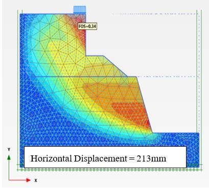
Thissectiondescribestheexaminationofinitialstabilityof slope without any shoring system. The analysis was performed using PLAXIS 2D software, C-Phi reduction methodiscariedouttodeterminethefactorofsafety(FOS).
Fromtheanalysisresults(Fig10)itisseenthatthefactorof safetyis0.34.Thefactorofsafetyislessthantherequired value of 1.5, indicating that the slope is unsafe. Hence, a suitableshoringsystemisproposed.

The analysis has been carried out considering micropile system only to retain a vertical cut of 6 m with an embedmentdepthof3m.Themicropiledesignconsistsof using 220 mm diameter steel pipe with 8 mm thick. Two steel bars of Fe500 having diameter 25 mm are used as reinforcementsinthepipe.

Fig -11: FactorofsafetywithMicropile
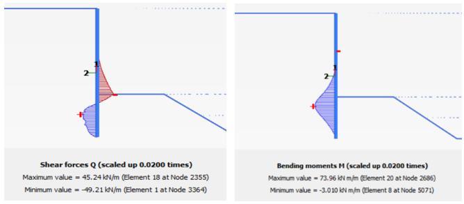
Theanalysisresultsshowthatthefactorofsafetyis0.89and thehorizontaldisplacementofmicropileattopis182mm Additionally, the shear force and bending moment values obtainedfromtheanalysisarepresentedinTable
Table 9 Shear Force and Bending Moment values

Fig -12: ShearForceandBendingMomentDiagrams
The analysis indicates that the slope is not stable with micropiling alone, suggesting that the slope requires a compositeshoringsystem,suchasmicropileandsoilnailing toachievestability.
Case 3: Analysis with composite shoring (Micropile and Soil Nail)
Inthiscaseuseofmicropileandsoilnailingwasnecessary becausethevariouscasesweredone withoutshoringand

International Research Journal of Engineering and Technology (IRJET) e-ISSN: 2395-0056
Volume: 12 Issue: 05 | May 2025 www.irjet.net p-ISSN: 2395-0072
micropiling,butthesoilwasnotenoughtostabilisetheslope tocarrytheload. Thesoilnailsoflengthof 6mwereused alongwithmicropile.

The analysis was initially carried out with a bottom nail spacingof1.2mfortheexcavationdepthof8.075m,using seven nails. However, the factor of safety obtained in this casewaslessthantherequiredvalueof1.5


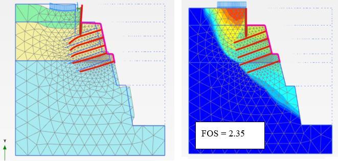
Fromtheanalysisresults,itisevidentthatthesystemissafe. Figure14showsthatthehorizontaldisplacementis0.14mm inthe topofmicropile,and Figure15 indicatesa factor of safetyof1.67,whichexceedstherequiredminimumvalueof 1.5.Aftertheanalysis,valuesforaxialforce,shearforce,and bendingmomentwereobtained.Basedontheanalysis,itis concludedthatthesystemdesignedfortheexcavationdepth of 17.075 m is adequate to resist the external loads, confirmingthatthesystemissafe

After the analysis, values for axial force, shear force, and bending moment were obtained. Table 10 shows the maximumvalues.
The dynamic analysis results are illustrated in the corresponding figure 17 and figure 18, and the computed factorofsafetyunderdynamicloadingwasfoundtobe1.67 Additionally, the maximum horizontal displacement observedwas8.79mminthetopofthemicropile.Compared tothestaticcase,thevaluesofaxialforce,shearforce,and bendingmomentincreasedunderdynamicconditions.


International Research Journal of Engineering and Technology (IRJET) e-ISSN: 2395-0056
Volume: 12 Issue: 05 | May 2025 www.irjet.net p-ISSN: 2395-0072

Fig -18: Deformedpatternofslope

Table 11 Comparison of Static and Dynamic results
The analysis is performed to evaluate the stability and deformationinvolvingatotalexcavationdepthof20.375m consistingofmultiplestagesataconstructionsite.Auniform surface surcharge of 72kPa is applied at the ground level adjacenttotheexcavationtoaccountfortrafficmovement. ThegeotechnicalpropertiesassignedarepresentedinTable.
Parameters Units Data
Soil Layer 1
Materialmodel Model Mohrcoulomb
Typeofmaterialbehaviour Type Drained Unitweightofdrysoil, unsat kN/m3 18
Materialmodel
Soil Layer 2
Model Mohrcoulomb
Typeofmaterialbehaviour Type Drained
Unitweightofdrysoil, unsat kN/m3 20
Unitweightofsaturatedsoil, sat kN/m3 22
Stiffness,Eref kN/m2 80*103
ROCK Layer 3
Materialmodel Model Hoek-Brown Typeofmaterialbehaviour Type Drained

Fig -20: GeometryoftheExcavationSection–3

International Research Journal of Engineering and Technology (IRJET) e-ISSN: 2395-0056
Volume: 12 Issue: 05 | May 2025 www.irjet.net p-ISSN: 2395-0072
Thissectiondescribestheexaminationofinitialstabilityof slope without any shoring system. The analysis was performed using PLAXIS 2D software, C-Phi reduction methodiscariedouttodeterminethefactorofsafety(FOS).

Fig – 21: SlopeStabilityAnalysis(FOS)
Fromtheanalysisresults(Fig-21)itisseenthatthefactorof safetyis0.46.Thefactorofsafetyislessthantherequired value of 1.5, indicating that the slope is unsafe. Hence, a suitableshoringsystemisproposed.
The analysis has been carried out considering micropile system only to retain a vertical cut of 3m with an embedmentdepthof2m.Themicropiledesignconsists of 220 mm diameter steel pipe of 8mm thickness filled with M25 grade concrete. The calculated micropile values is assignedintheTable
Table 6.13 Properties of Micropile

Fig -22: FactorofsafetywithMicropile
Theanalysisresultsshowthatthefactorofsafetyis0.71and thehorizontaldisplacementofmicropileattopis45.98mm Additionally, the shear force and bending moment values obtainedfromtheanalysisarepresentedinTable
Table 14 Shear Force and Bending Moment Values

Fig -23: ShearForceandBendingMomentDiagrams
The analysis indicates that the slope is not stable with micropiling alone, suggesting that the slope requires a compositeshoringsystem,suchasmicropileandsoilnailing toachievestability.

International Research Journal of Engineering and Technology (IRJET) e-ISSN: 2395-0056
Volume: 12 Issue: 05 | May 2025 www.irjet.net p-ISSN: 2395-0072
Inthiscaseuseofmicropileandsoilnailingwasnecessary becausethevariouscasesweredone withoutshoringand micropiling,butthesoilwasnotenoughtostabilisetheslope tocarrytheload. Thesoilnailsoflengthof 6mwereused alongwithmicropile

TheGroutednailsconsistof25mmdiameter,6mlongTMT barasshowninFigure6.35with150mmdiameterdrilled holeswith20°inclinationwithrespecttothehorizontal.The groutednailstartsat4.0mbelowfromtoplevel.Thespacing at1.30mofnailsinhorizontalandverticalshallbedoneina staggeredmanner.

Fromtheanalysisresults,itisevidentthatthesystemissafe thehorizontaldisplacementisobtainedhas2.38mm.Figure 25(a)showsthatthe deformedshapeofthemicropileand soil where the upper part of the soil and micopile is
displaced outwards and the bottom most part of the soil displacedinwards andindicateseverystage ofexcavation the obtained factor of safety is greater than 1.5. After the analysis, values for axial force, shear force, and bending moment were obtained. Based on the analysis, it is concludedthatthesystemdesignedfortheexcavationdepth of 20375 m is adequate to resist the external loads, confirmingthatthesystemissafe

After the analysis, values for axial force, shear force, and bending moment were obtained. Table 15 shows the maximumvalues.
MICROPILE
SHEARFORCE(kN/m) BENDINGMOVEMENT(kN-m/m) 1559 1397
Nail AxialForce (kN/m) ShearForce (kN/m) Bending Movement (kNm/m)
1 2924 171 0455
3 3517 1
4
5 4421 260 0
Table 6.15 Static analysis results
The dynamic analysis results are illustrated in the corresponding figure 27 and figure 28, and the computed factorofsafetyunderdynamicloadingwasfoundtobe2.35 Additionally, the maximum horizontal displacement observedwas5.72mminthetopofthemicropile.Compared tothestaticcase,thevaluesofaxialforce,shearforce,and bendingmomentincreasedunderdynamicconditions

International Research Journal of Engineering and Technology (IRJET) e-ISSN: 2395-0056
Volume: 12 Issue: 05 | May 2025 www.irjet.net p-ISSN: 2395-0072


-28: ShearForceandBendingMomentDiagrams
Comparedtothestaticcase,thevaluesofaxialforce,shear force, and bending moment increased under dynamic conditions.
Table 6.16 Comparison of Static and Dynamic results
The study presented a comprehensive numerical investigationofdeepexcavationstabilityusingacomposite shoring system comprising micropiles and soil nails. Excavationprofilesrangingfrom12 mto21 mdepthwere analyzedusing PLAXIS 2D, under bothstaticanddynamic (seismic)loadingconditions.Thestagedanalysisconsidered different configurations: no shoring, micropile-only, and combinedmicropile-soilnailsystems.
1. Withoutanyshoring,theslopewashighlyunstablewith a factor of safety (FOS) significantly below the acceptablelimit(1.5).
2. Asthedepthofexcavationincreases,thedisplacement ofsoilnailwallalsoincreases.Theglobalfactorofsafety above 1.5 is achieved by combined micropile and Soil nailsystem.
3. Duringbothstaticandseismicconditions,themaximum displacementoccursatthetopofthemicropile.
4. In a shoring system, the minimum bending moments andshearforceinthemicropileareobservedinthecase ofthestaticanalysiswiththemaximumshearforceand maximumbendingmomentsareobservedinthecaseof dynamicanalysis.
5. Shoringsystems(micropileandsoilnailing)consistently yielded the highest FOS (up to 2.25) and the lowest horizontaldisplacementsunderbothstaticandseismic loading.
6. Duetotheenhancedstrengthofmicropilewithnailing, themaximumhorizontaldisplacementisalmostnearer inbothstaticanddynamicconditions.
7. Theeffectoftrafficloadontheexcavationisstudiedby varyingtheloadfromtheexcavationline,anditisfound thatlowerthetrafficloadtotheexcavationareagreater willbethedisplacementscausedandvice-versa.
8. Indynamiccondition,thedisplacementsandtheforces in the micropile are more when compared to static condition.
9. Underseismicconditions,allsystemsshowedreduced FOScomparedtostaticcases,butthecompositesystem stillmaintainedacceptablesafetymargins.
1. Amit Srivastava, Pawan Kumar, G.L.Sivakumar Babu (2012)“Stabilityanalysisof18mdeepexcavationusing micro piles”. Proceedings of Indian Geotechnical ConferenceDecember(scribd.com)13-15,2012,Delhi.
2. Farouk&Hamza(2009)“BehaviorofMicropilesunder verticaltensionandcompressionloads”.Proceedingsof the17thInternationalConferenceonSoilMechanicsand Geotechnical Engineering. doi:10.3233/978-1-60750031-5-1243

International Research Journal of Engineering and Technology (IRJET) e-ISSN: 2395-0056
Volume: 12 Issue: 05 | May 2025 www.irjet.net p-ISSN: 2395-0072
3. Georgiana, Nicoleta, Gheorghe (2016) “Mathenatical modelling for Micropiles embedded in salt rock” MathematicalModellinginCivilEngineeringVol.12‐No. 1:23‐35‐2016Doi:10.1515/mmce‐20160003.
4. Midhula&Chandrakaran(2015)“NumericalSimulation of Soil Nailed Structures” International Journal of EngineeringResearch&Technology(IJERT)ISSN:22780181Vol.4Issue08,August-2015.
5. Morteza Esmaeili, Morteza Gharouni Nik and Farid Khayyer(2013)“ExperimentalandNumericalStudyof Micropiles to Reinforce High railway embankments”, International journal of geomechanics. DOI:10.1061/(ASCE)GM.1943-5622.0000280.
6. DeepakHooda,AnupamMittal(2017),“Studyofmicropiles subjected to lateral loading and oblique pull”, Internationaljournalofadvanceresearchinscienceand engineering. Volume no 6, issue no 1, pp. 369-374. Railway Embankments”. American Society of Civil Engineers DOI: 10.1061/(ASCE)GM.19435622.0000280.
7. Rakesh Kumar Dutta and Anish Pandit (2013). Performance of Rectangular footing on loose sand reinforced with micropiles” Indian Geotechical Journal(Octoberhttps://doi.org/10.1007/s40098-0230725-4.2023)53(5):1053–1063
8. Shu-Wei Sun,Ben-Zhen Zhub, Jia-Chen Wang (2013) “Design method for stabilization of earth slopes with micropiles” The Japanese Geotechnical Society. http://dx.doi.org/10.1016/j.sandf.2013.06.002
9. Tae-HyunHwang,Kang-HyunKim,Jong-HoShin(2016) “Effectiveinstallationofmicropilestoenhancebearing capacityofmicropiledraft”TheJapaneseGeotechnical Society.Soil and Foundations 57(2017) 36-49 www.sciencedirect.com DOI: 10.1016/j.sandf.2017.01.003ISBN:00380806
10. William K.Howe,S.M.ASCE, Denver (2010) “Micropiles for Slope Stability”. ASCE ascelibrary.org by on 08/27/15.