Digital Farbrication Lab (DF Lab)
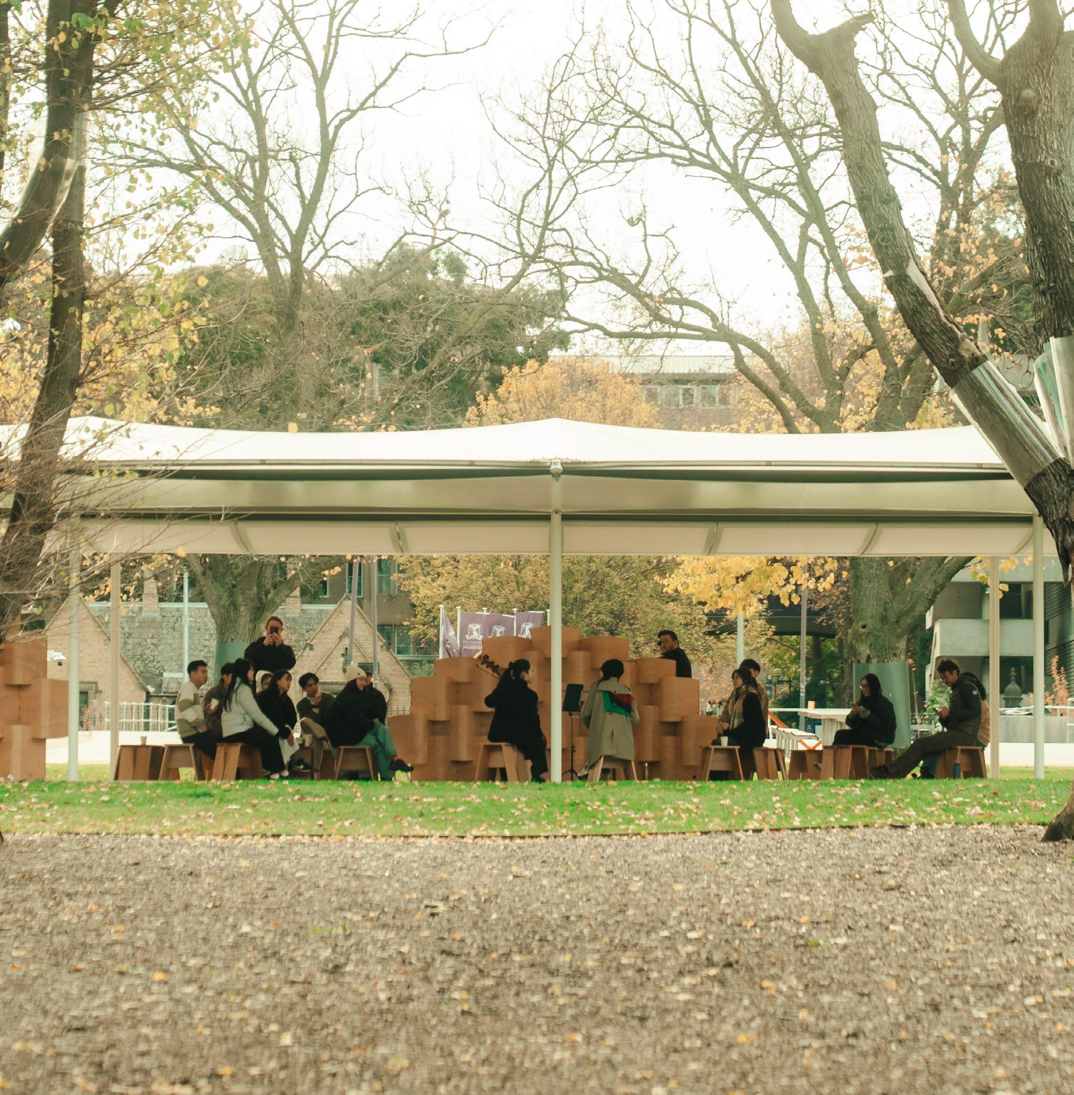
Acoustic Pavilion, MPavilion Parkville
Team work
Melbourne, VIC, Australia
2025 Feb. - June.(Semester 1 In Melbourne Univeristy)
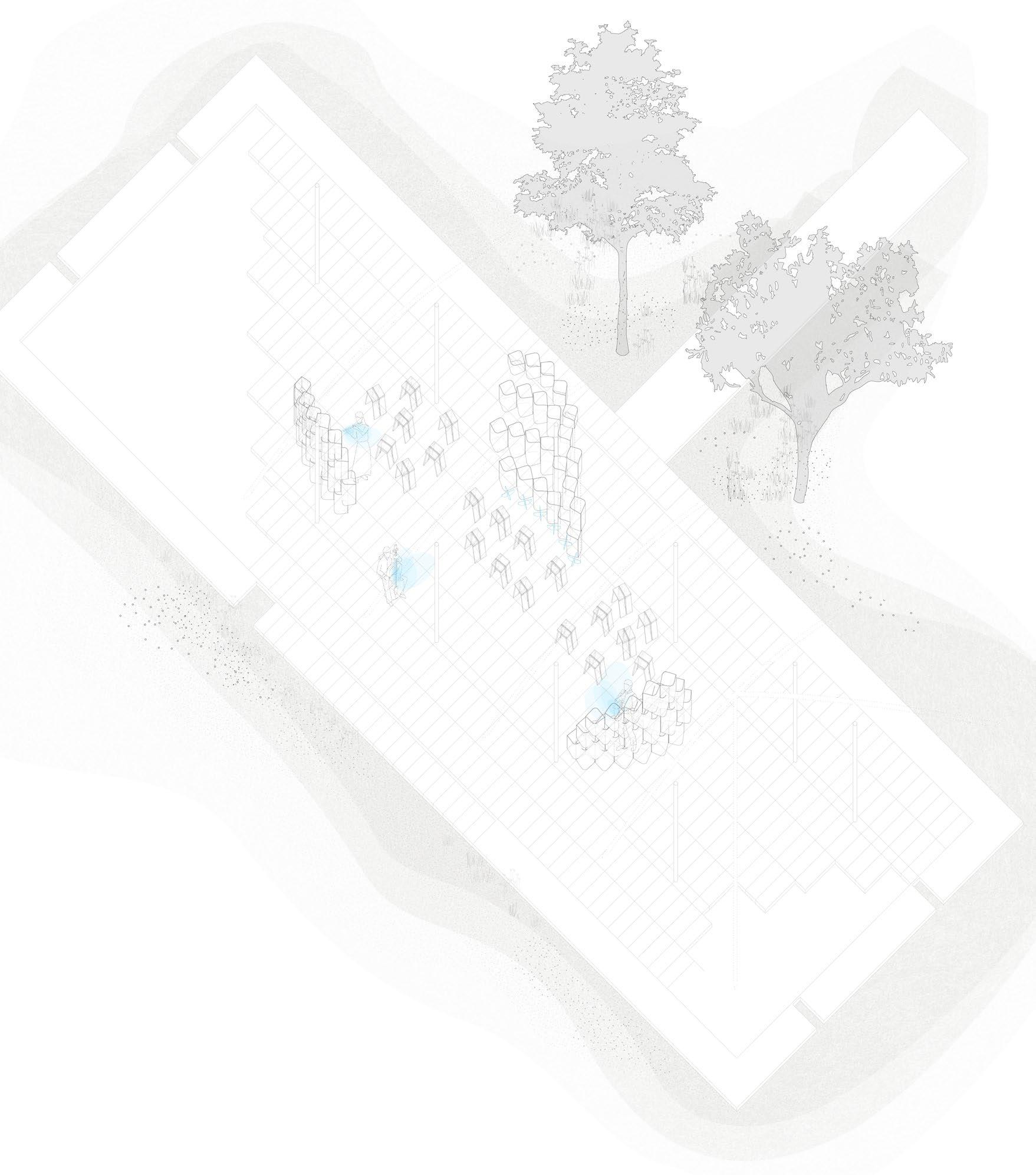
Sonular (Sonus + Modular) is a modular acoustic pavilion designed and built by Architecture students in the elective DF_Lab: Designing Making, at the Faculty of Architecture, Building and Planning. DF_Lab (Digital Fabrication Lab) asked students to explore architectural design through making, combining traditional craft techniques and material affordances with digital technology and algorithmic design tools.
In this iteration, students collaborated with musicians from the Melbourne Conservatorium of Music to design a deployable acoustic pavilion for outdoor performance. The students leveraged parametric design and a modular kerfing panel system to achieve a bent plywood panel that can scatter sound. The panel and wall configurations went through digital iterations to simulate and optimise the acoustic performance and physical prototyping to test the digital fabrication workflow and material and structural properties.
Sonular serves as a prototype for multidisciplinary collaborations between architectural design, digital fabrication, acoustics, and music.
Tutors:
Michael Mack
Jack Halls
Designers:
Monica Ko | Gia (Parker) Chenh | Jing Xian (Dalius) Chua Wing Laam (Tamae) Yu Nicholas Pang
Ellin Minogue Tianhui (Zoe) Feng | Long-Lee Chen | Nicholas Liao Vivian Xu | Xinyue Qiu
Roy AlBayeh | Liang Xiong (San) Alexandra (Sasha) Khomenko Liam O'Donnell
BAISC INTRODUCTION
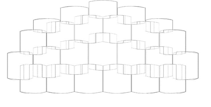
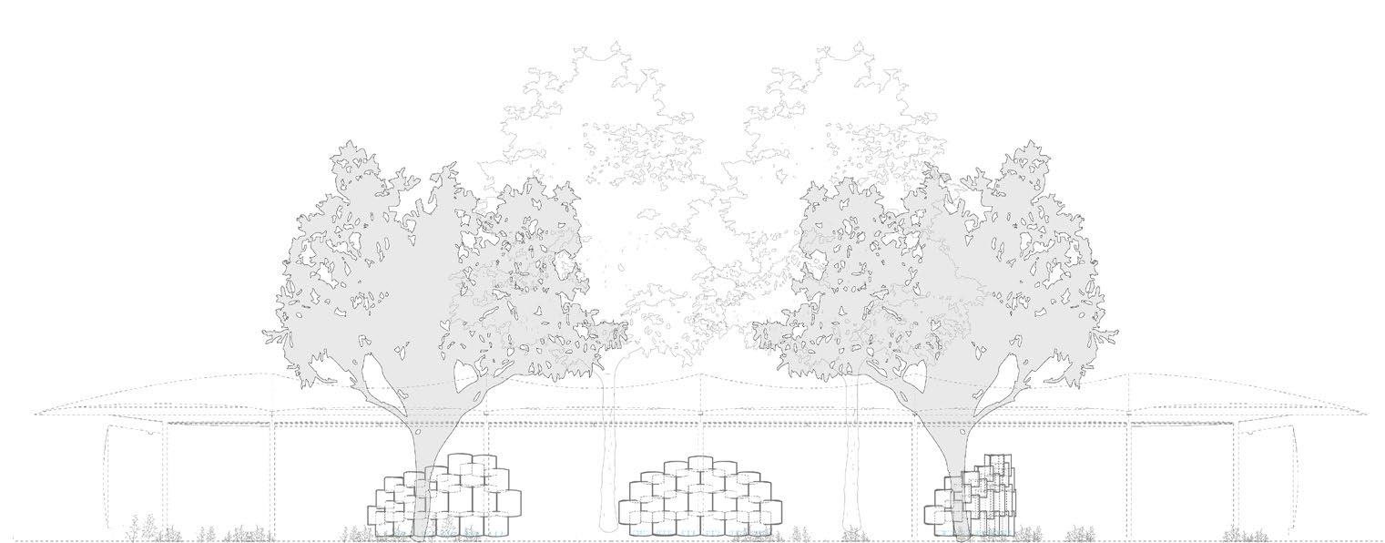
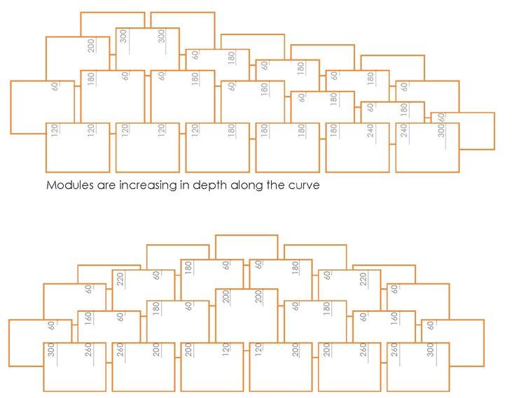
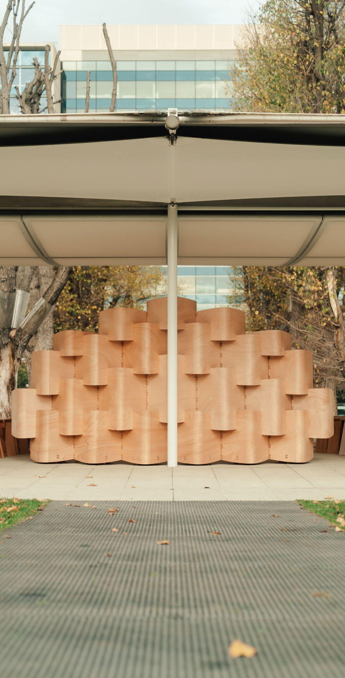
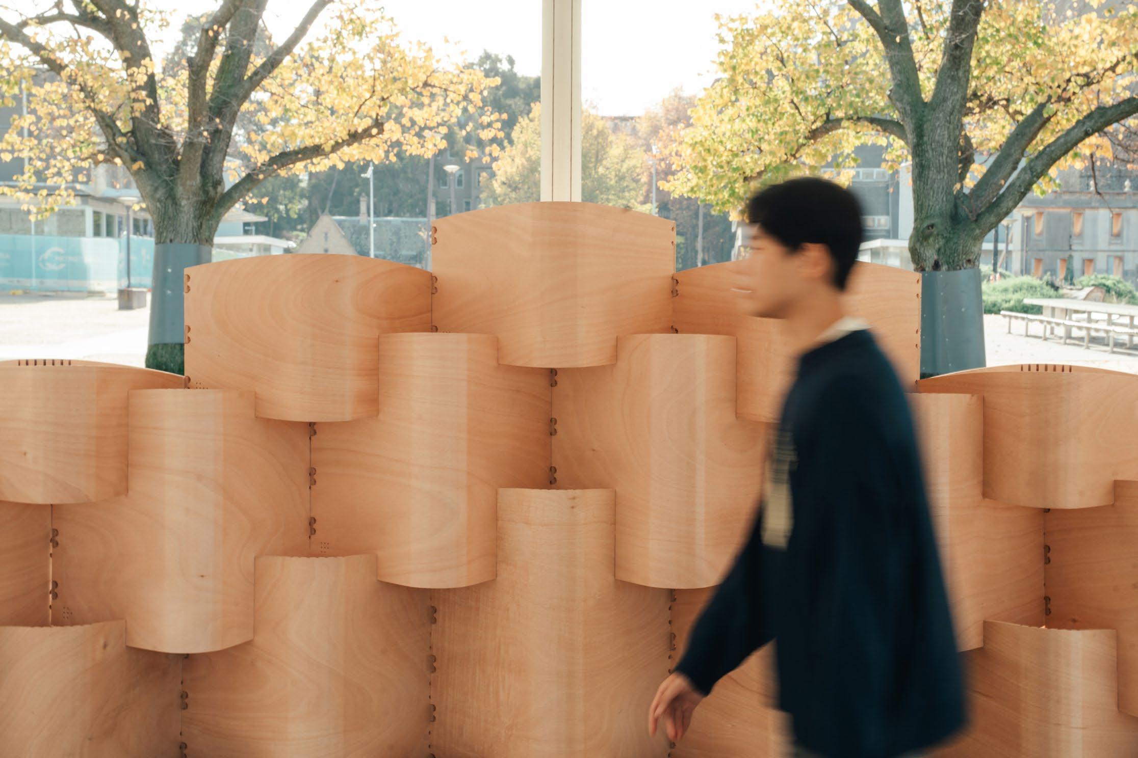
Each ‘wall’ segment consists of a series of modules with change in heights to form the overal ‘curve’ in elevation. This repetition allows for both visual rhythm and tailored acoustic performance, as the number of modules can be increased or decreased in the future to support different musical ensembles and sonic requirements.
OVERALL WALL
Consisting of a series of modules, the design is articulated as three distinct parts, each assembled using a consistent language while varying in their overall configuration. Although the underlying geometry remains uniform, the arrangement of each wall part responds to different acoustic and spatial requirements, resulting in an asymmetrical composition that is both cohesive and dynamic.
A deliberate variation in module heights introduces a sense of fluidity to the visual language, echoing the curved features embedded within each module’s form. This subtle modulation not only enriches the pavilion’s architectural expression but also reinforces the relationship between structure and sound, allowing the wall to function as both an acoustic device and a sculptural presence within the site.
DIGITAL OPTIMISATION
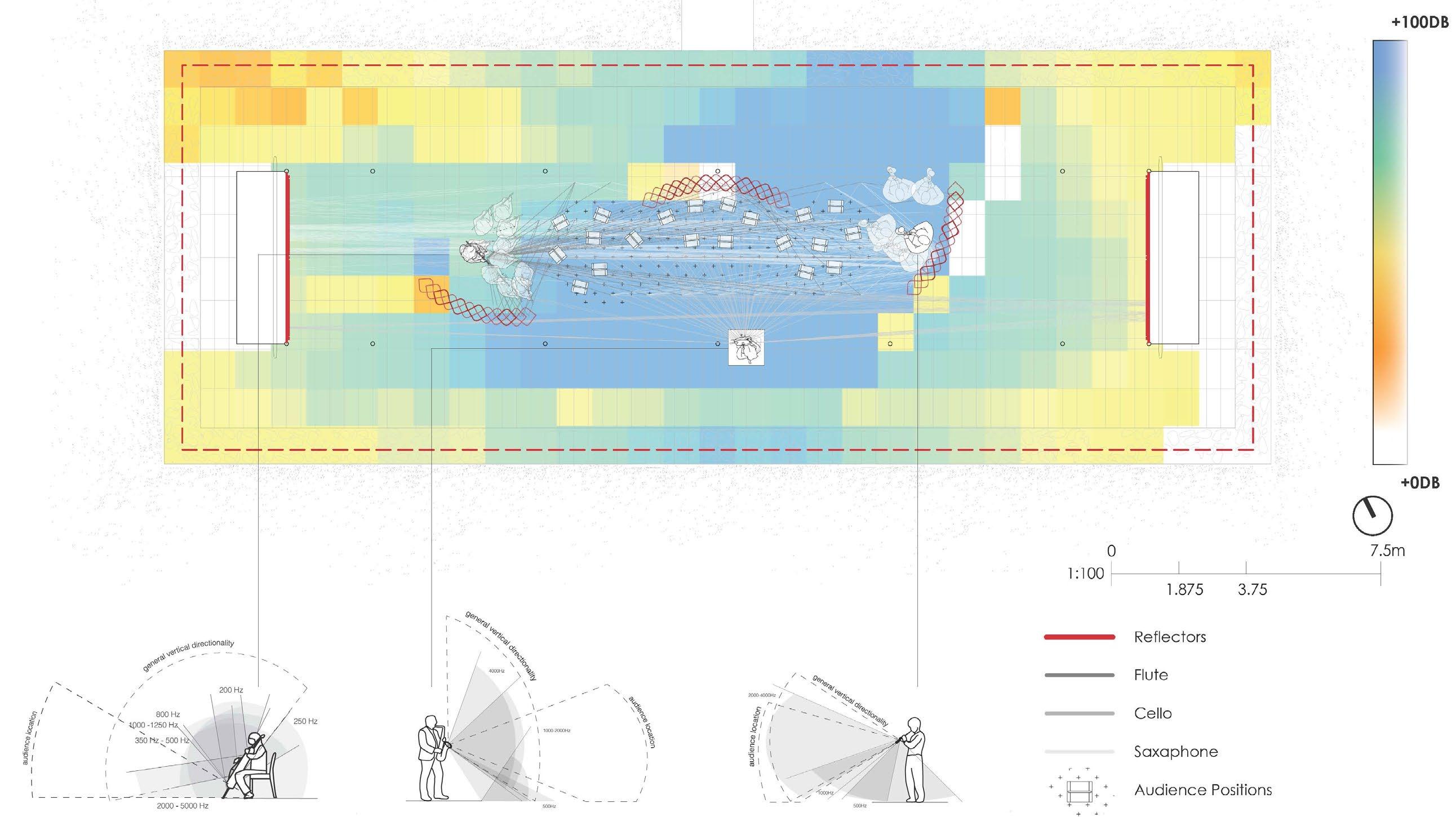
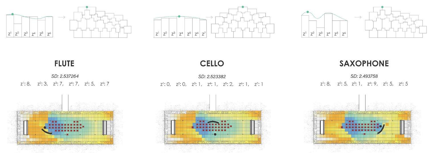
A key feature of the design is an undulating wall that varies in height. To optimise its acoustic performance, the height modulation was digitally refined using an evolutionary solver, allowing for a rationalised peak and overall form. The wall is divided into seven segments, aligned with the modular grid. The amplitude of the extrusion determines the height of each segment, shaping a dynamic yet controlled acoustic surface.
Where z is the multiple to determine the height of each column:
Column Height = 0.56+z(0.12)
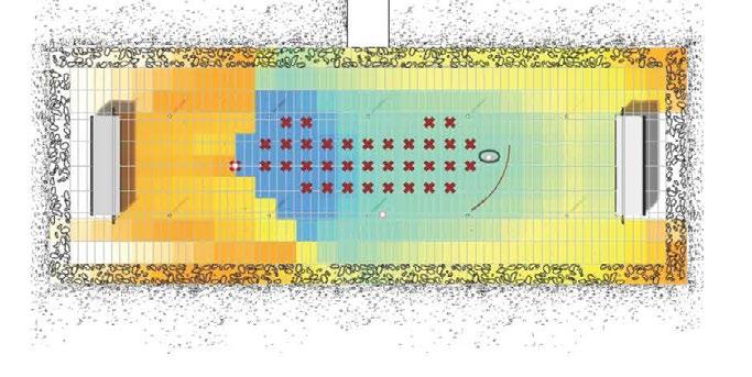
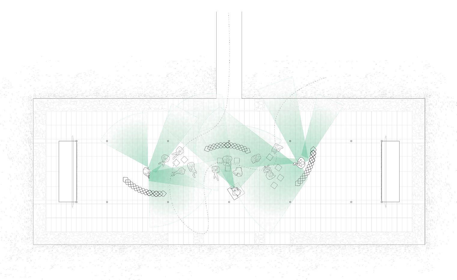
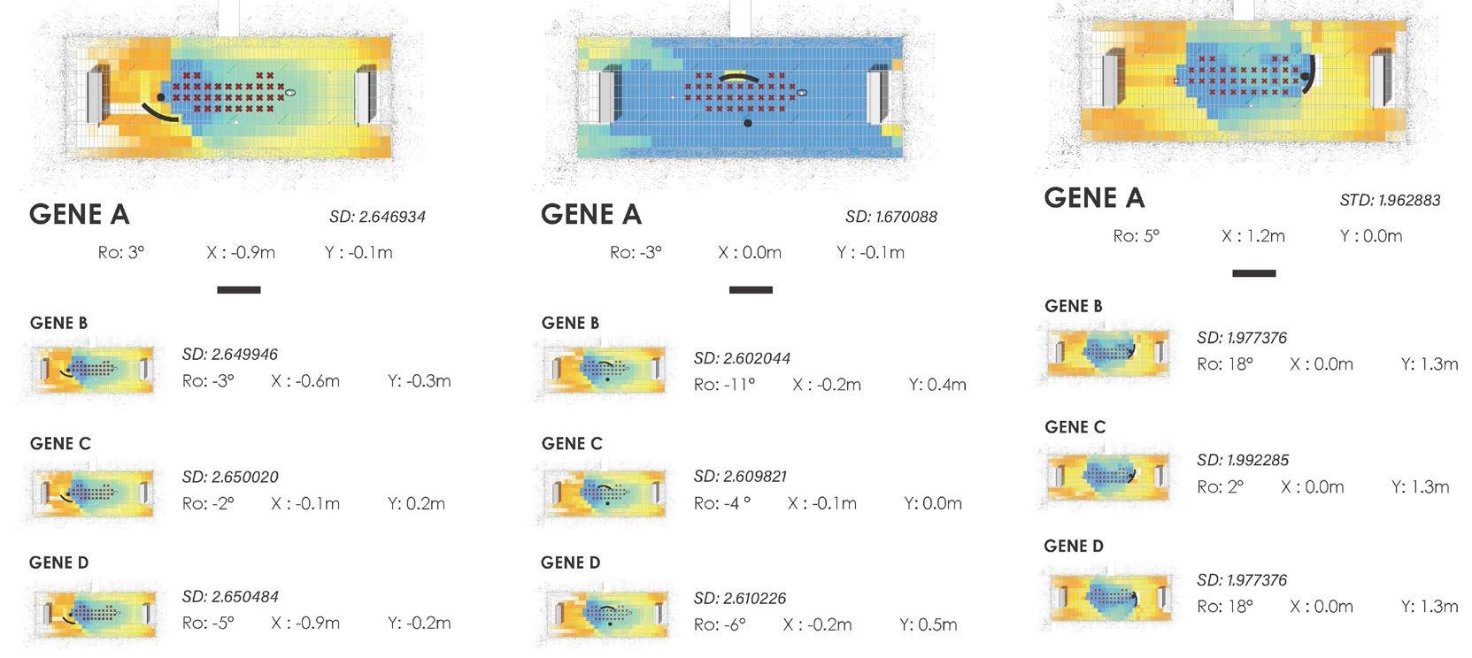
This SPL (Sound Pressure Level) map visualises the decibel distribution from the three musicians/ instruments in the absence of the Sonular Pavilion.
Serving as the control condition (Standard Deviation: 2.641), it establishes a reference point to evaluate the acoustic impact of the pavilion’s design.
WALL POSITION

The wall's initial placement is determined by design intent, musician position, audience capacity, and MPavilion structure. It is then optimized digitally using an evolutionary solver with parameters like rotation and amplitude along the X and Y axes.
For the saxophone, parameters are set to Rotation (Ro): 0°–45°, X-axis: 0.0–2.0 m, and Y-axis: 0.0–2.0 m to avoid overlap with the performer.
FLUTE CELLO

BRACING ITERATION
Hinges Design Multi Notches Design
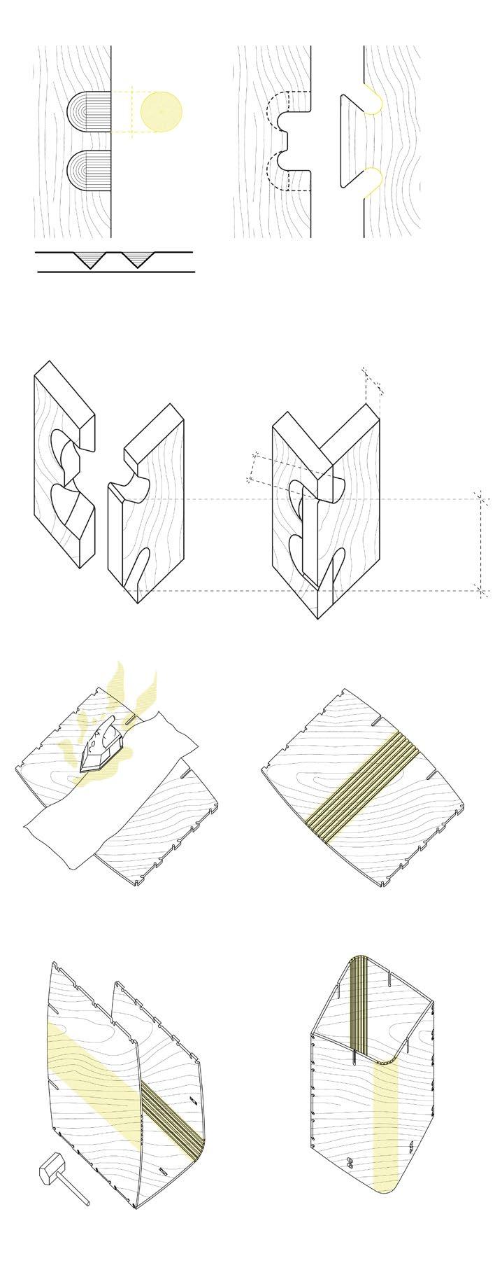
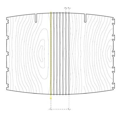
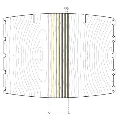
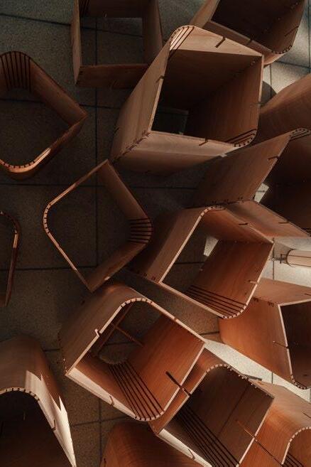
Flexibility was one of the key criteria for the hinges / notches team. Initially, and the team looked at accounting for 5 to 10 degree interval bends. CNC Tool: 45 Deg V-mill
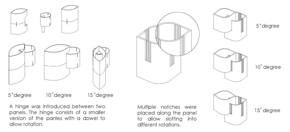
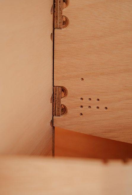
A hinge was introduced between two panels. The hinge consists of a smaller version of the panles with a dowel to allow rotation.
Multiple notches were placed along the panel to allow slotting into different rotations.
NOTCHING LENGTH
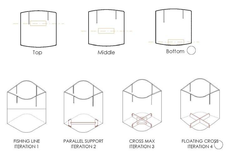
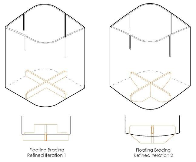
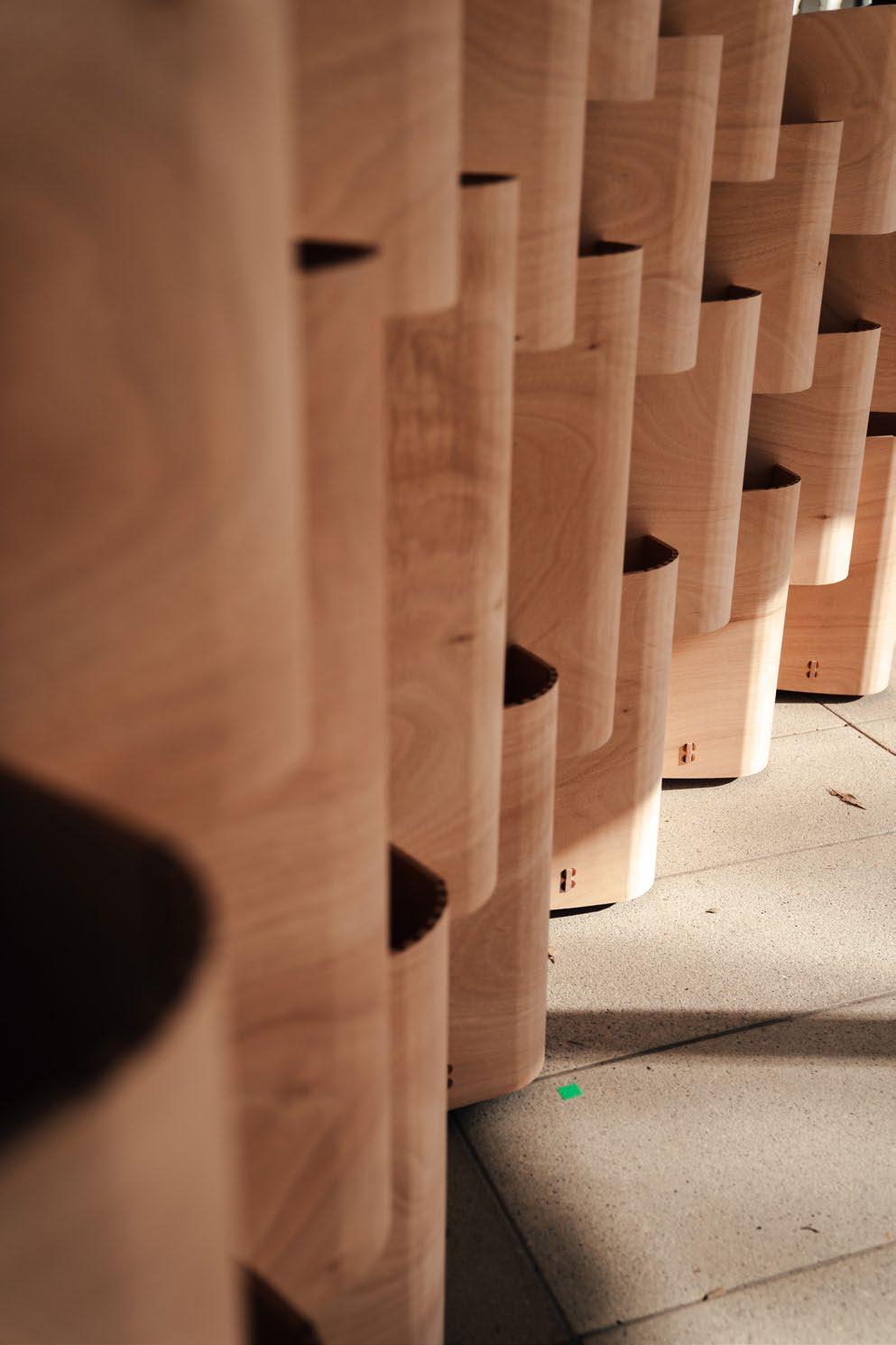
Iteration 4's bottom bracing was chosen for aesthetics and feasibility. The team accidentally discovered levitating panels, which added an interesting and aesthetic touch. Further exploration was done.
A floating bracing created a levitating effect, while chamfered edges ensured a seamless finish at the ground level. The shadow line enhanced this levitating appeal.



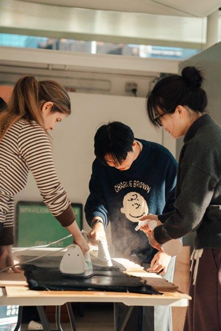
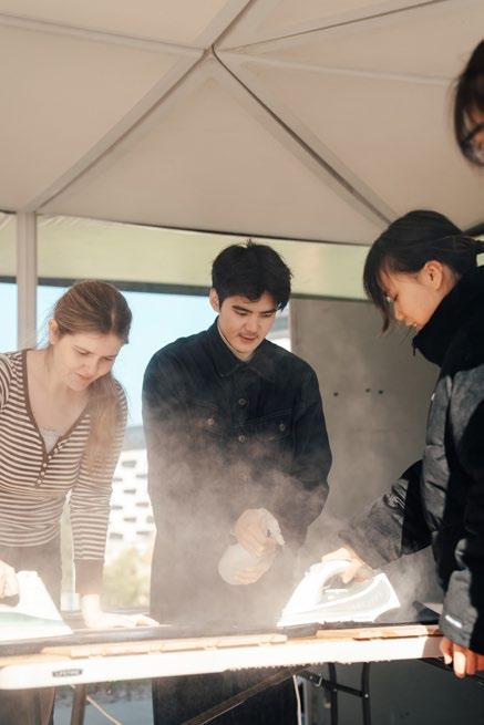

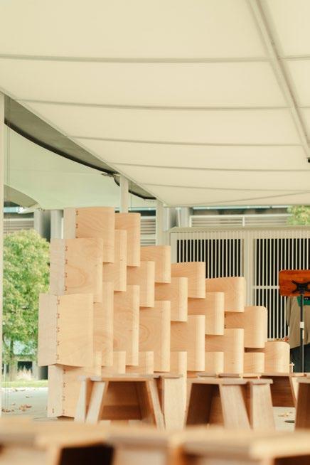

JUST FOR FUN~
SPATIAL 3D-PRINTING TECHNOLOGY OF SURFACE
Team work
TianJin province, China
2022 Feb. - MAY.(Fourth Year In Univeristy)
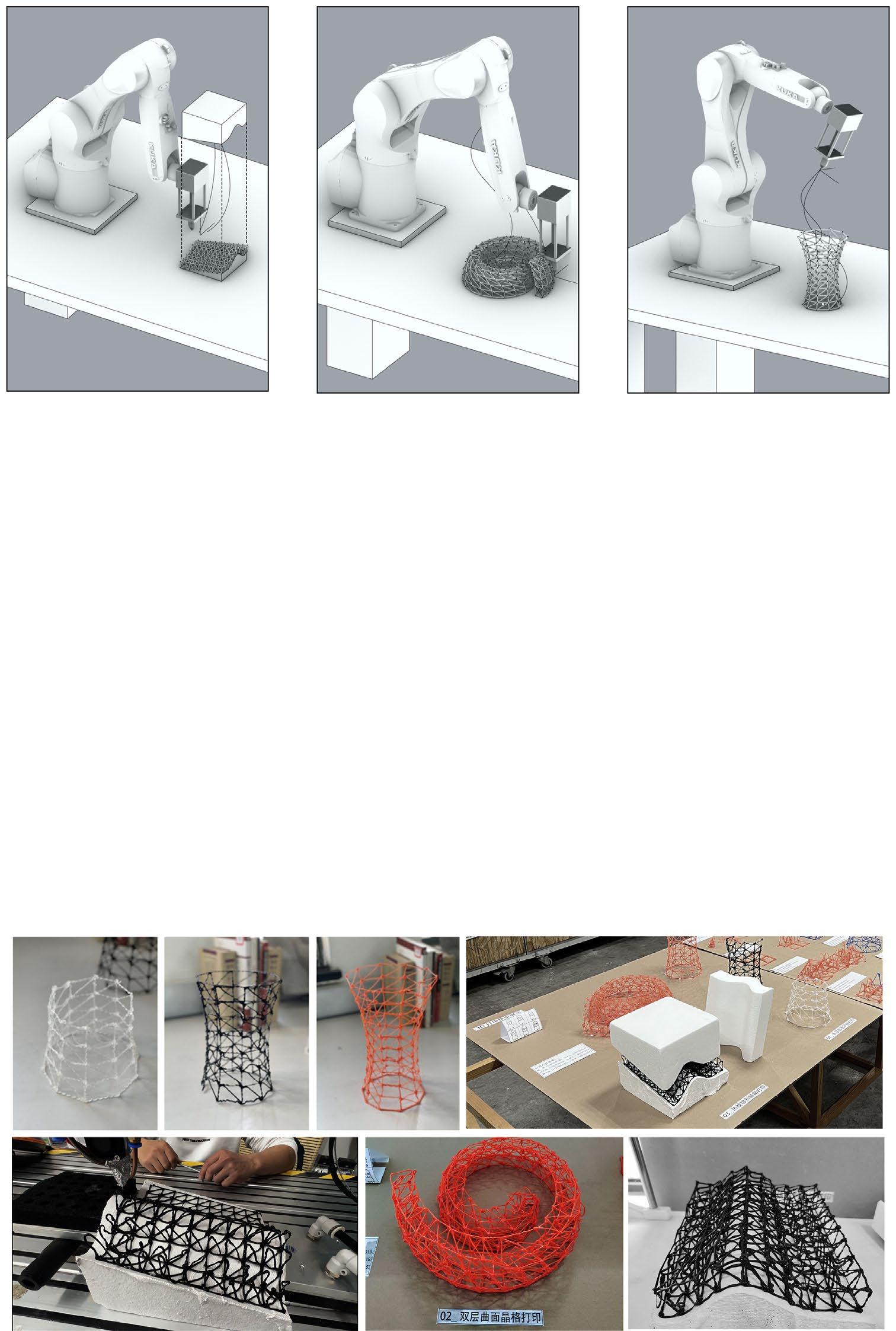
Robot construction using digital information can improve the manufacturing accuracy of complex components, as well as work efficiency and shorten construction time. The robot arm system includes a robot arm and an end effector, as well as control systems, operating equipment, connecting cables, and peripheral devices such as protective devices, transport devices, and sensors.
The robot arm system has the ability to imitate human arms and has unique and flexible operational capabilities. By coordinating the six axes of the robot arm itself, the origin of the tool coordinate can accurately reach a certain point in space, and then the signal will be output to the tool head through the robot arm's signal output, commanding the robotic hand to perform the action. After the robotic hand has completed the action, it will input feedback signals to the robot arm. After receiving the signal, the robot arm can proceed to the next action.

WHAT is spaitial 3d-printing technology of freeform surface
Robot construction using digital information can improve the manufacturing accuracy of complex components, as well as work efficiency and shorten construction time. The robot arm system includes a robot arm and an end effector, as well as control systems, operating equipment, connecting cables, and peripheral devices such as protective devices, transport devices, and sensors.
The robot arm system has the ability to imitate human arms and has unique and flexible operational capabilities. By coordinating the six axes of the robot arm itself, the origin of the tool coordinate can accurately reach a certain point in space, and then the signal will be output to the tool head through the robot arm's signal output, commanding the robotic hand to perform the action. After the robotic hand has completed the action, it will input feedback signals to the robot arm. After receiving the signal, the robot arm can proceed to the next action.
TWO METHODS of spaitial 3d-printing
3D-PRINTING(DIRECTLY)

HOT-LINE CUTTING &3D-PRITING
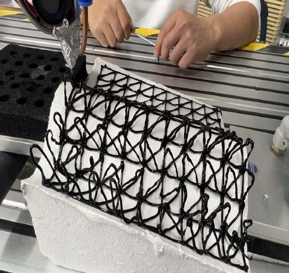
Finding the MOST APPROPRIATE PARAMETERS (blowing speed, material, robotic arm movement speed and temperature) is A MOST IMPORTANT FACTOR that directly affects the aesthetics of the final result.
MATERIAL

1.Transparent: #Cheap #Crunch #Breakable
2.White: #Soft #Expensive #Elastic
3.Orange:(most effective) #Colorful #Toughness, #Contrallable #Expensive
4.Blue #Colorful #Elastic #Soft
Drawing:X(Speed)(based on the 0.45m/s)-Y(Score)
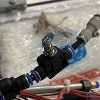
However, the wind speed adjustment is based on the knob, and it is difficult to adjust based on data. Therefore, we keep the wind speed within a suitable range and focus on adjusting other items.
[ ONE ] REPEATED PATH
Since the points generated by modeling do not conform to the actual printing order, there are many repeated paths.
[ TWO ]JITTER CURVE
The speed of discharging materials is much greater than the speed of movement of the robotic arm.
[ FOUR ]PROTECT FOAM BOARD
The high temperature of the gun tip will melt the foam base, so you need to put a plaster cloth on it for heat insulation.
[ FIVE ]CLOSED PATH
The double-layer structure requires each layer to form a closed loop, so the movement path is obtained taking into account the structural support and nonrepetition of trajectories.
[ SEVEN ]OPTIMIZE PATH
[ THREE ]OFFSET STARTING POINT
If you start printing the finished product directly, it will be difficult to maintain the appropriate temperature at the glue outlet. So a track will be reserved
FAST SLOW
[ SIX ]DEBUGGING PARAMETERS
The moving speed of the hot wire cutting machine is too fast or too slow, which will directly affect the surface smoothness of the underlying foam base plate.
ODD NUMBERED LAYERS
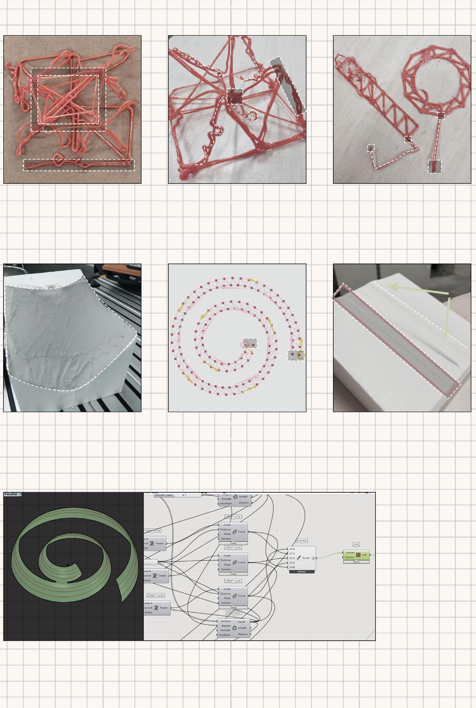
First use hot wire to cut out the foam block and then 3D print on the block. Space feasibility needs to be considere.
Print on a regular plane, but horizontal path closure needs to be considered. The main difficulty lies in path optimization.
DIVIDE SURFACE
FINAL RESULT EXHIBITION [ Hard ] OPTIMIZE PATH(evaluation standard) [ Medium ] [ Easy ]
It is a relatively simple printing model, and the main difficulty lies in debugging parameters. It directly determines the quality of the finished product.
SURFACE SURFACE POINTS POINTS POINTS POINTS POINTS POINTS POLYLINE POINTS POINTS POINTS POINTS POINTS
EVEN NUMBERED LAYERS
The order of path activities in odd-numbered layers and even-numbered layers is completely opposite, and the tree structure relationship of the paths needs to be adjusted.Finally, the model is optimized to obtain the relationship characteristics of oddnumbered layers and even-numbered layers respectively. Draw a closed path clockwise Counterclockwise
