






Editorial Board
Geoff Mutton
Jeff Smit
Technical Editor
Jeff Smit
Sub-Editor
Cameron McGavin
Scan Data Director
Rod Maher
Technical Research
Brendan Sorensen
Technical Assistance Moderator
Scott Thomas
Technical Contributors
Brendan Sorensen
Mark Rabone
Frank Massey (UK)
Jack Stepanian
Sam Nazarian
Jason Smith
Clinton Brett (Diesel Help)
Technical Assistance Team
Deyan Barrie Andrew Kollosche
Sideth Chiv Maurice Donovan
Gil Sher Anthony Tydd
Wayne Broady Jason Smith
Marty Hosie Jack Stepanian
Mark Rabone Rob Romano
Daniel Armer Jack Mackay
Gary O’Riain
Associate Team Members
Gary Homan Peter Hinds
Columnists
Geoff Mutton (TaT Biz)
Advertising Enquiries
Paul Woods,
National Advertising Manager
E: pwoods@tat.net.au
Ph: 0494 044 958
Graphic Design
Brigid Fraser
E: production@tat.net.au
PH: 0413 009 122
Affiliated Associations
AAAA – info@aaaa.com.au
Capricorn Society Alliance Supplier
VASA – secretary@vasa.org.au


The Soapbox is a familiar perch for Jeff Smit, and rightly so. He has carried an enormous load for TaT and the trade for longer than I’ve been allowed near the good tools.
In this issue of TaT, I’m adding another voice alongside him on the Soapbox, and you’ll see me up here regularly. Not to take anything away from Jeff, who is still going from strength to strength, but to help keep the work that matters moving at a sensible pace. He has been a mentor to me for years and remains tireless – hopefully he does not overdo things. Inside TaT we have looked at our list and asked the questions. What is mission-critical? What needs a specific person’s unique experience? What can be shared, documented or delegated without losing quality? That is part of why you are reading me here. The aim is simple – to help make the best use of our team’s time and attention while keeping the momentum you expect from TaT
The same thinking, applied in a workshop, is a practical survival move. If you are the owner, foreman or go-to tech, you cannot grow your capability or your business if everything routes through you. There is a ceiling you will hit and it is usually made of late nights and missed family dinners.
So here is a simple framework to try.
• Stop – Take 10 quiet minutes. No phone. List the repeated tasks that eat your day.
• Sort – Mark which items truly need your signature or experience. Then mark the ones that could be handled by a staff member with clear steps, a short brief and check at the end.
• Shift – Move one task this week. For example, have a younger tech do the initial scan and report to you with what they believe the diagnostic plan should be.
• Support – Provide the tools, checklist and context; align with front of house (FOH) so the plan and promise match.
• Review – Own the outcome. Give feedback. Adjust the process. Repeat. None of this is about dropping standards. It’s about building them into more of your people. That younger employee who keeps asking questions, they are signalling where you can invest time now to gain time later.
We know the objections: it’s faster to do it myself; customers expect a consistent, professional voice at the counter; last time it bounced back into my face. Sometimes true – but fast today can be slow forever and structure beats muscle memory.
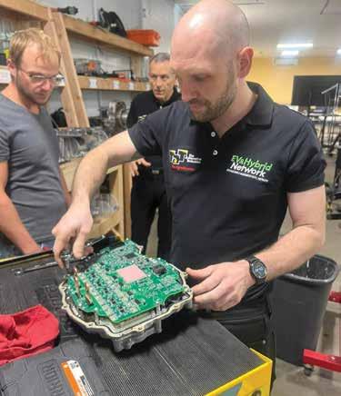
What does structure look like in practice?
• For diagnostics – Use a simple template: complaint, history, confirmed symptom, test plan, results, analysis, next step. Hold junior techs to the template and praise the process, not just the answer. The greener the technicians, the more checkpoints they pass through with you – the goal is to just increase the time between checkpoints.
• For FOH – Does the service advisor really need to pull a tech off a job to help reply to a technical email or could they ask Tech Tina – a professional technician ready to answer any question they have – on the TaT website?
• For housekeeping – Assign scan-tool updates and restocking consumables to build ownership with low risk.
The gain from this is not just hours freed. You lift the ceiling on the work your shop can take on. A young tech who learns to plan a diagnostic job becomes a mid-level tech who closes jobs faster with fewer comebacks. A mid-level tech who learns to structure information with FOH becomes a senior who can run a bay without you hovering. The compound interest on that is real.
Back to Jeff. This is not a changing of the guard. He has spent years giving his time to build people up. Many of us stand a little taller because of it. My stepping in here is simply adding capacity so he can keep doing what he does best. That is exactly what we are asking you to try in your workshop.
So stop for a moment and have a think. Is it time to involve a staff member a little more, expand their role and give them responsibility with the support to succeed?
Pick one change and start this week – review, then repeat. You’ll gain time to tackle the seemingly never-ending tasks that keep the doors open and the standards high – and you might just make space for someone else to find their voice.

Brendan Sorensen
You had a firm pedal before, just did a routine brake-fluid flush and now your stomach is sinking as much as the brake pedal that refuses to firm up.
Modern brake systems can turn a simple maintenance bleed into an all-day drama if you’re not armed with the right knowledge, tools and a few tricks.
Most technicians are comfortable with pressure bleeders, vacuum bleeders and classic pedal-pumping – they’ve all been around for decades.
What’s made things trickier today is the sheer number of places for air to hide. Modern systems pack in complex valve networks, accumulators and full electro-hydraulic boosters. Each of these introduces more fluid paths and extra chambers where air can get stuck, making it far easier to wind up with a soft pedal after a routine bleed, even when nothing was wrong to begin with.
Pressure, vacuum or the pedal pump?
• Pressure bleeder: Hands down, a professional pressure bleeder is the best option for most workshops. These keep the master cylinder topped up under pressure, ensuring a steady flow through every line and forcing air out of stubborn anti-lock braking system (ABS) or modulator blocks.
If you’ve got the option, start here every time. The only real pitfalls are cheap kits with poor sealing caps (which usually make a huge mess as they pressure-leak fluid everywhere) and using too much pressure (risking blown seals). One bar (about 15psi) is plenty – no need to overdo it.
• Vacuum bleeder: Vacuum bleeding is popular because it’s a genuine one-person job and it works well – until it doesn’t. You can also fool yourself by constantly seeing air bubbles coming out in the clear hose of the tool.

2. There are plenty of pressure bleeders on the market – let us know what you think of yours on the TaT Equipment Reviews page.
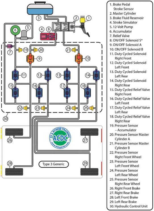
1. The hydraulic brake circuit in a typical hybrid or EV has many areas for air to hide.
When you apply vacuum at the caliper, air can be drawn into the bleed hose at the threads of the bleed screw. This shows up as bubbles in the outgoing fluid, which can make it hard to judge if all the air is truly out of the system, even though these bubbles don’t affect pedal feel.
• The classic pedal-pump bleed: Still valid if you’re careful but it won’t do the full job on a modern system. Pedal-bleeding can trigger ABS/stability-control faults and simply fails to move air out of trapped valves or accumulators.
Submerged hose: The one-person trick that can help I’ve had cases where no amount of vacuum or pressure seemed to bring the pedal back but the old submerged-hose trick did. Here’s how to do it:
• Fill a container with clean brake fluid.
• Attach a clear hose to the caliper or wheel-cylinder bleed screw.
• Submerge the free end in the container so it stays below the fluid surface.
• Crack open the bleed screw and gently pump the pedal. Because the hose end is always under fluid, any air coming out is seen as bubbles but as the pedal returns, only fluid can be drawn back – not air. You don’t need the old ‘up, down, up, down!’ routine and you don’t have to keep closing the bleed screw. It’s simple, controlled and avoids reintroducing air.
• Why it works: The submerged hose acts as a one-way valve. The fluid column in the hose can’t suck air back into the caliper but it will show you when bubbles are truly gone.
More systems are turning to an electro-hydraulic brake master/ booster assembly, particularly in hybrids but also a huge range of 4WDs and European vehicles.

These systems feature a pump and accumulator, so they can generate and modulate hydraulic pressure without pedal input. If you’re flushing fluid on one of these, avoid just pumping the pedal. Most will have an OE brake-bleed function that can be found in most aftermarket scan tools.
The tool will command the pump to cycle, opening valves in sequence to push out any air trapped in the actuator or accumulator while instructing you which corner of the vehicle to open a nipple on. Traditional bleeding just doesn’t reach the extra internal chambers; pressure has to be applied and valves cycled by the system itself.
Why you get a soft pedal after a simple flush
On certain vehicles (I’m looking at you Renault Master), it’s not uncommon to finish a routine bleed only to find a soft pedal, even if you never let the reservoir run dry and had a good pedal beforehand.
The exact cause is still debated but experience shows that particularly vacuum bleeding alone can allow air to enter the system, possibly due to low pressure zones or pulling past marginal internal seals.
In these cases, switching to pressure bleeding or finishing with the submerged-hose method is your best path back to a firm pedal.
It is becoming more common for an internal ABS module valve to fail to seat after being cycled during a scan tool-assisted flush, particularly on poorly maintained systems that haven’t been bled in years. This allows an internal leak in the hydraulic system, bleeding off pressure through the leaking valve (basically the same thing that happens during ABS operation when the valve opens), giving a soft pedal.
Cycling the ABS valves with a scan tool or carrying out a heavy ABS braking event may temporarily restore the seal but it’s often a sign of pitting or poor seat surface on the valve, meaning the soft pedal can return at a later date, typically after the ABS has cycled again. This issue typically requires replacement of the ABS module’s hydraulic valve block.
Rapid rescue: What to do if the pedal won’t come back
1. Double-check your bleed method: If you used vacuum, try pressure or submerged hose to finish.
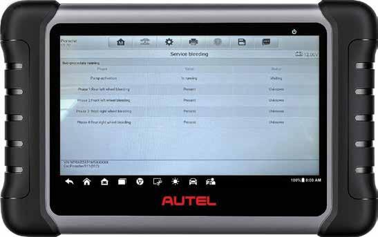
4. Most modern vehicles have an accompanying brake-bleed scan-tool function, especially electro-hydraulic setups.
2. Clamp all four flex hoses: If the soft pedal remains, it’s likely in the master or ABS module. Pedal now firm? Release clamps one at a time – when the pedal goes soft, you’ve found the corner to focus on.
3. Check for new leaks such as weeping bleed screws or fluid at the master-cylinder pushrod.
4. If you suspect ABS module air, a proper scan-tool bleed routine to cycle all actuators is worth trying. The next diagnostic step is to fit blanking fittings to the master-cylinder outputs (typically M10 x 1mm thread). If the pedal is now hard but becomes soft again when you move the blanks to the ABS module outputs, the problem must be in the ABS module.
Tips from the trenches
• Keep reservoir topped: Of course this goes without saying but if not pressure bleeding, I strongly recommend utilising a clip-on style reservoir-refiller tool.
• Hybrids and electro-hydraulic boosters: Always follow the OE bleed routine; it is often guided in your scan tool and is the only way to ensure old fluid doesn’t remain in unopened areas.
• Use clear hose on the submerged method: So you can see air bubbles.
Sidebar: Why fluid should be flushed every two years
Hygroscopic brake fluid absorbs moisture from the air, which lowers its boiling point and increases the risk of corrosion and valves sticking inside ABS and brake-by-wire modules.
A two-year flush keeps water, dirt and corrosion out of the expensive parts, makes maintenance bleeds easier and help avoids the headaches outlined in this article.
Final word: Don’t let a routine bleed become a comeback
In our experience, nearly every ‘soft pedal after a flush’ headache can be solved by switching bleeding methods or rebleeding with the right approach.
Professional pressure bleeders are your best bet to not find yourself in this situation to start with. A pressure bleeder, or the submergedhose trick, is what usually helps me when I’m the third guy called over to have a crack at the ‘unbleedable’.
If you’re still getting no-where, having a clean syringe of brake fluid to gently reverse the flush from caliper back might even be the ticket on that very troublesome vehicle. For hybrids, EVs and models with electro-hydraulic boosters, the scan tool is your friend – use it. Most of all, don’t panic – a good pedal is nearly always just a different method or two away.

Jeff Smit
Liquidcooling systems have been a vital part of motor vehicles since the first production cars appeared on our roads.
For decades, the design approach for these systems was simple – use a water pump, radiator and thermostat to prevent the engine from overheating. The aim was clear –remove enough excess heat to avoid damage and keep the vehicle running reliably.
This steady evolution took a sharp turn in 2005 when Australia officially aligned with global emissions-reduction targets. From that point, vehicle manufacturers started implementing a variety of new technologies aimed at lowering emissions and the cooling system – or more precisely, the thermal-management system – became a key part of achieving these goals.
Traditionally, the main function of the internal combustion engine (ICE) cooling system was to dissipate excess heat to prevent premature component wear or catastrophic failure. As engine outputs increased over the years, so did the demands on these systems.
In modern engines, however, managing heat has become much more subtle. Excess heat remains problematic in some cases but in others heat can be a helpful partner. The challenge is no longer just dissipating heat but regulating it to keep different parts of the powertrain at their ideal temperature during various stages of operation.
By 2018, the term cooling system was already outdated. Manufacturers started calling these setups thermalmanagement systems (TMSs) – integrated solutions that control the warm-up and cooling phases of the engine, turbocharger, heater core and even the transmission.

So what’s the ideal operating temperature for an ICE?
The science of engine heat
In an ICE, the combustion of fuel and air creates heat energy. This energy is split roughly into three parts:
• One-third is converted into mechanical work, pushing the piston down.
• One-third exits with the exhaust gases.
• One-third is absorbed by the engine’s metal components and then transferred to the cooling system.
Historically, the goal was to dissipate this absorbed heat as quickly as possible. Nowadays, we understand that running an engine hotter – within safe limits – can enhance fuel efficiency. This is because higher operating temperatures decrease heat loss during combustion, enabling more of the fuel’s energy to be transformed into usable work.
However, there’s a catch. If the temperature gets too high, pre-ignition or knocking can happen, which lowers efficiency and threatens engine damage. The solution is to increase the operating temperature during light-load cruising (to boost efficiency) and decrease it during high-load operation (to prevent knocking).

• Short answer: As hot as possible –without causing knock or damaging components.
• Long answer: Water (H2O) is a by-product of combustion. If all components in the combustion chamber remain above 100°C, this water stays in vapour form and exits through the exhaust. If temperatures drop below 100°C, condensation can occur, leading to corrosion and oil contamination.
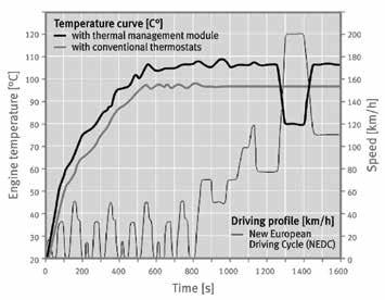
For this reason, many modern petrol engines with advanced TMS setups run (pic 1):
• Low-load cruising: ~105-107°C.
• Full-load operation: ~85°C.
This dynamic temperature control can only be achieved with advanced systems such as the thermal-management module (TMM).
The thermal-management module (TMM)
One notable example of modern cooling technology is Schaeffler’s Thermal Management Module, used on various Audi and Volkswagen models with the EA888 Gen3 engine (pic 2 and 3).
The TMM combines the water pump with two electronically controlled rotary valves, completely replacing the traditional thermostat. The water pump is belt-driven from the rear of the balance shaft and a finned pulley draws cooling air through the housing to prevent the belt and pulley from overheating.
The ECU commands the rotary valves, offering eight distinct coolant-flow strategies:
1. Cold start – No coolant flow to allow rapid warm-up.
2. Auxiliary heating – Directs heat to the cylinder head, turbocharger and heating, ventilation and a/c (HVAC) system.
3. Partial cooling – Maintains moderate temperatures for light-load operation.
4. Engine-oil cooling – Transfers heat from engine oil to coolant.
5. Transmission-oil cooling – Regulates automatic-transmission temperatures.
6. Low-load cooling – Maintains ~107°C for optimal efficiency.
7. Full-load cooling – Drops to ~85°C to prevent knock.
8. Turbocharger cool-down – Postshutdown coolant circulation to protect the turbo.
Feature Traditional thermostat system
Warm-up control
Coolant distribution
Temperature range
TMM-equipped system (EA888 Gen3)
Fixed thermostat opens at a set Can completely shut coolant flow during temperature (~90 °C) warm-up for rapid temperature rise.
One fixed bypass to radiator
Limited control
Two rotary slide valves manage coolant flow with precision between block, oil cooler, heater core and more.
Dynamic control from ~80 °C up to 110 °C depending on load and conditions.
Warm-up speed Slower ~30% faster block heating, reducing time to reach oil temp by ~50%.
Efficiency and emissions Standard
Complexity
Simple, mechanical setup
For Australian workshops, understanding the principles and operation of modern thermalmanagement systems is becoming essential. Diagnosis is no longer just a matter of checking coolant flow or replacing a stuck thermostat. Technicians must now consider:
• ECU-controlled coolant strategies.
• Integration with transmission and oil cooling circuits.
Improved thermal efficiency, reduced fuel use and CO₂, better cabin comfort.
More complex, integrating electronically controlled valves and unified module assembly.
• Turbocharger after-run cooling cycles.
• The relationship between temperature control and emissions compliance.
As vehicle technology continues to evolve
– particularly with the rise of hybrid and electric vehicles (EVs) – the role of thermal management will only grow. For ICE, EV and hybrid platforms alike, controlling temperature precisely is the key to performance, efficiency and component longevity.


Clinton Brett
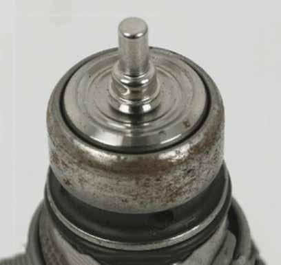
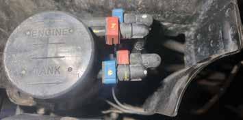
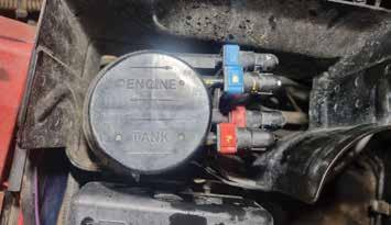
These Bosch pressure regulator valves (PRVs, pic 1 and 2) are distinctively different from other OE valves that you may have seen on rails. These units are common on diesel vehicles from Audi, BMW, Jeep, Mercedes-Benz and VW.
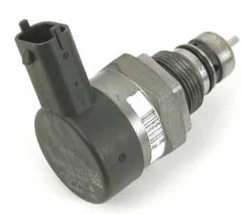

enabling the rail pressure to increase and decrease, depending on what the ECU demands at the time.
The pressure valves mounted to rails without an electrical harness are referred to as hydraulically and mechanically operated pressure-limiting valves.
This means that when high fuel pressure is present within the rail, the hydraulic force will overcome the spring holding the valve in place, releasing it from the seat, returning fuel to the low-pressure return circuit and relieving the fuel system of pressure. The valve spring immediately overcomes the void and snaps closed on the valve seat, preventing further fuel from exiting and an immediate drop in pressure.
In my experience, this type of valve is less reliable. Repeated opening weakens the spring and wears the seat, causing it to leak over time and leading to earlier failure than the electronically controlled type. In contrast, an electronically controlled fuel-
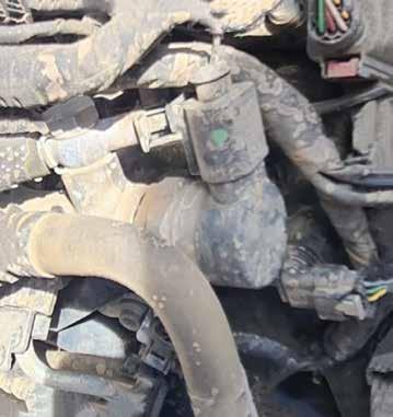
input signals, providing a more accurate and reliable way to regulate fuel-rail pressure.
As soon as the ignition is switched on, the fuel-rail pressure (FRP) sensor monitors rail pressure. The FRP sensor relays this information to the ECU, which modulates the PRV position. Opening the valve increases return flow and lowers rail pressure; closing it restricts return flow and raises rail pressure according to engine load and demand.
Here’s an example I find is easier to understand. Using a garden hose with an adjustable spray nozzle, rotating the nozzle to provide a fine mist fan appearance of the water reduces the flow of water, yet you can feel the harsher effect of the water on your hand. At the same time, you can feel the pressure building in the rubber hose. When opening the nozzle to change the fine spray to a more direct flow, you create an increased flow of water but less pressure. In a situation when pressure is too high in the system, the ECU will command the PRV to open, relieving the system of excess pressure.
There are many good features about this pressure-control valve. One of them is it is failsafe, particularly as protection against over-pressure, which can cause engine failure.
Here at Diesel Help, we have been motivated by our clients to offer an online training course on this subject, as well as publishing my articles in this magazine. There appears to be quite a bit of misunderstanding of such valves in common-rail diesels (CRDs).
For example, the rail valve – which is mounted to the rail and often overlooked – is electronically controlled and is often mistaken for a sensor.
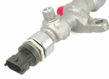
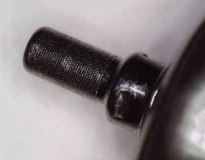
where the fuel-rail pressure sensor on the opposite end of the rail is operated by three wires. In some engines using a V6 or V8 configuration, one rail will be fitted with the FRP sensor (pic 3) and the other fitted with this fuel-pressure regulator.
The other way to determine the design of the rail is the outlet shown here (pic 4). It uses either a banjo bolt and banjo fitting or a quick-release fitting (pic 5).
Common faults and issues experienced with these fuel-rail pressure control valves include pressure being too high, too low or a no-start.
In situations where we have experienced ‘pressure too high’ codes, such as P0088, the cause has often been a restriction in
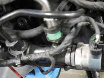
the tiny filter (pic 6 and 7) on the internal end of the pressure regulator. Due to the restriction of fuel flow through the control valve, the rail pressure increases, triggering a fault code.
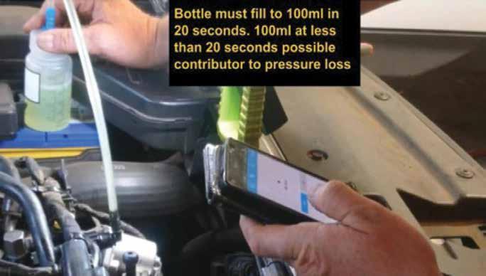
The other issue we often see is that the steel seat can become worn by contamination, creating an uneven surface or a failed seal, allowing the rail valve to leak excessive fuel from the rail. There are some easy test methods which we’ve created for sorting out this issue. If possible, start the vehicle and monitor the fuel flow from the return outlet (pic 8). This should be approximately 100mL in 20 seconds (observe diesel safety
and route the return into a suitable container).
In any situation, once the pressure regulator has been confirmed as failed, replace the entire rail assembly. Most rail valves and sensors are not replaceable as they do not have a specified torque setting and do not come with a replacement gasket or seal. Without these, you can’t guarantee a reliable seal or you can easily overtighten and distort the valve or sensor.
• For more information about Diesel Help’s services and training courses, go to dieselhelp.com.au

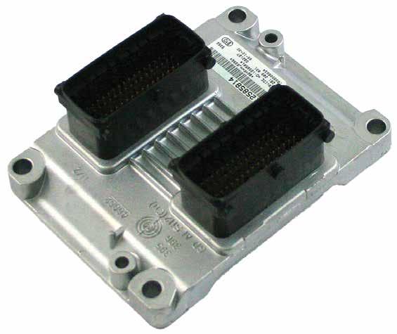
Injectronics continues to deliver industry-leading solutions its remanufactured GM Alloytec V6 ME9.6 ECM (CO code: 0261209025CO), supporting a wide range of Holden vehicles including the Adventra, Colorado, Crewman, One Tonner Rodeo from 2005 to 2012.
This changeover product is designed to provide a quick, dependable alternative to traditional ECM repairs, with each unit rebuilt to surpass OEM standards. A key feature of this process is Injectronics’ use of ultrasonic wire-bonding technology, an advanced method that guarantees strong internal connections and long-lasting durability, particularly in high-vibration settings.
Technicians benefit from reduced turnaround times and streamlined ordering. Once the

faulty part number and vehicle details are confirmed, a precoded unit is promptly dispatched. Programming is required on installation but Injectronics’ technical support and documentation help to make integration seamless.
Injectronics changeover units are engineered to resolve a range of known faults, including:
• No crank.
• Misfiring.
• Fuel gauge error in dash cluster.
• Injector circuit faults (P0201–P0206).
• Canister purge-valve fault (P0443). This remanufactured ECM is designed to deliver exceptional value and performance. Whether addressing intermittent no-starts, misfires or fuel-control issues, Injectronics’
changeover service ensures vehicles are quickly back on the road with a reliable, thoroughly tested unit.
With a national distribution network and decades of expertise, Injectronics continues to set standards in automotive electronic remanufacturing.
• To find out more, go to injectronics.com.au

This vehicle wasn’t at my shop but Deks Auto Repairs, a shop across town.
The vehicle had been at another shop for three months before it was sent to Derek. It had driveability issues and an initial scan came up with:
• P0642 – Sensor reference voltage A circuit low.
• P0106 – Range performance manifold absolute pressure/barometer pressure circuit range.
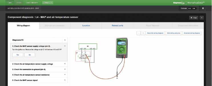
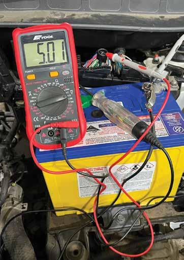
The manifold absolute pressure (MAP) sensor had already been replaced, so we sourced a diagram from Haynes (pic 1) and started to test for power and grounds, which appeared OK until the vehicle was driven. Soon after we took off, the check-engine light (CEL) would illuminate and we had drivability problems. The fault code logged again for the MAP sensor and on testing we found the 5V reference had dropped out (pic 2).
The fault continued to reoccur after clearing the code but usually only when driven. When it lost the 5V reference, it would sometimes come back fast and other times take a while to return. It could idle for 30 minutes or more with no issues but log soon after driving.
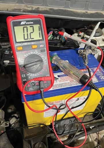
We wiggle-tested the loom and got the ECU hot but that didn’t affect the 5V reference (pic 3). We decided to get a second-hand ECU and had the original cloned. Unfortunately, this didn’t fix the problem.
After some research – special mention to the Doctor, Scott Thomas – we were advised there were multiple 5V reference bars internal to the ECU that supplied the 5V to multiple wires exiting the ECU. I hadn’t known this.
We were advised to disconnect all the sensors until the 5V reference was restored. I told Derek and he disconnected every sensor on the engine with no change. He also disconnected the transmission – still no change.
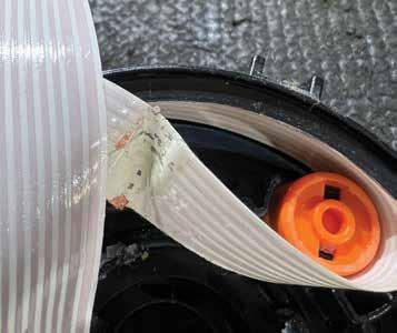
Then he proceeded to probe all wires from the ECU in an attempt to find any other 5V reference that had been dragged down. After finding one, he then looked at a wiring diagram and traced it to the clock spring. Disconnected the clock spring and all other plugs reconnected. The car now started and ran fine.
Sourced and fitted another clock spring, cleared the codes and road-tested the vehicle with no returning faults.
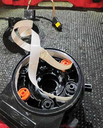
- Anthony Tydd 1
No doubt a few of you might say, ‘Why not test all the wires coming out of the ECU in the first place?’ and after reading this story, it’s easy to think, ‘Yes, that’s a pretty good idea.’
But this was intermittent with no other codes – I’m still not sure why there wasn’t an airbag code with the MAP code. So we had nothing pointing to other sensors until we had cloned and cleared the ECU of acting alone in this evil course of events.
Once you knew it was the clock spring at fault, the correlation was easy to see. The steering wheel could be in the right spot to short or just near. If it was moved getting in or out, or the car was moved to a different spot in the workshop, it could potentially trigger the fault. The fault didn’t trigger a light every time the wheel was moved either, so it wasn’t like you could just move the wheel and the CEL would come on (pic 4 and 5).
5 4
The time I spent on this was between jobs and after hours, so hard to calculate, but it would run into days, that’s for sure.
The main reason I wanted to share the experience is because, firstly, I didn’t know there were 5V reference bars inside the ECU – I hadn’t really given it much thought! And you don’t get to find out what sensors are paired on what bar.
I also didn’t know you could have a sensor –a clock spring, in this case – drag down other sensors and cause them to log a code, all the while it was sitting up the back laughing and not logging any involvement at all.
I hope this is educational for more people than just us.
This 2015 Kia UM Sorento with 234,984km on the clock came in with its check-engine light (CEL) illuminated and the engine down on performance. The customer reported the vehicle had been to another workshop. It had replaced the transmission control module (TCM) and internal wiring harness in the automatic transmission but the fault had persisted. Road-tested the vehicle and found the transmission was in fail-safe mode, stuck in fourth gear.
Back in the workshop, a scan of the vehicle revealed the DTC, P0880 – TCM power input signal.
Followed the factory fault flow chart and load-tested both permanent power and key power to the TCM ground – both tested OK,
indicating the TCM had good power and earth.
Checked both TCM power outputs to the transmission solenoids and no power was present.
Tested the continuity of both wires – they were good. Checked for a short to ground and found the red wire (power 1 wire) shorted to ground.
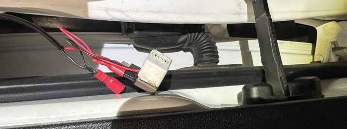
Installed a piezo buzzer to this wire and performed a wiggle test – found the short behind the interior blower-motor box against the interior firewall.
This area is impossible to access without removing the dash, so cut the red wire at both the TCM and transmission plug, then ran a new wire.
Cleared the codes and road-tested the vehicle – it was now all OK.
Diagnostic time for this job was three hours and repair time two hours.
Graham Hamilton Hamilton Automotive Services GOONELLABAH, NSW


Frank Massey
In this article I’m going to take you through a very interesting diagnostic challenge with a Hyundai Tucson 2.0 CRD.
It’s only fair to explain from the outset there was no confirmed conclusion to the tests conducted; the value here is in the process and my opinion on the results.
The first problem was the vehicle history. It was bought from an eBay account, originally listed for $AU5000 but reduced by $AU2000 when our customer viewed the vehicle with an engine-performance problem.
Obtaining a detailed triage from an owner is the first vital step to a quick and accurate diagnosis. We were told attempts were made to rectify the fault by the previous owner prior to the sale. I suspect this was the reason for the sale.
The vehicle mileage was modest at approximately 110,000km and outwardly it appeared in good condition. The problem was its engine-running issues. The fault was intermittent and unpredictable in nature.
Regrettably, I wasn’t the first tech to attempt a repair, although I did not necessarily disagree with some of the actions taken. There were no diagnostic trouble codes (DTCs). Because of the poor idling, the decision was taken to remove and benchtest the injectors. This was conducted by Diesel Bob in the Lancashire outback –equivalent to your Northern Territory – but what is important here is I always trust and respect his judgement completely. His conclusion was the balance was slightly out, though not sufficient to cause the symptoms.
The decision was taken to have the injectors fully overhauled, with the new coding programmed into the Bosch powertrain
control module (PCM). A new pressure-regulation valve (DRV) was also fitted with no change in symptoms whatsoever.
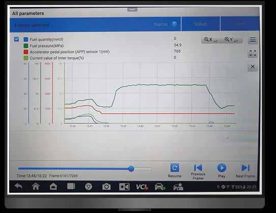
You may note from my logs that rail pressure did increase independently of accelerator pedal-position (APP) input, suggesting a sticking DRV valve (pic 1 – fuel pressure increase, no APP input request).
This is the point I become involved. Having rechecked the PCM for DTCs and correct injector coding, I decided to connect my low-pressure/flow gauge with extension hoses to evaluate low-pressure (LP) fuel supply in the vehicle, establishing the symptoms while monitoring LP priming and fuel cavitation.
Always observe diesel safety when doing this – use diesel-rated hoses, eye protection and keep clear of high-pressure (HP) lines. I can confirm that when the faults were demonstrated, low pressure remained steady at 450 kilopascals (kPa) with no cavitation.
The vehicle had an erratic idle at all times, hot or cold, with the engine speed rising and falling slightly. Static open-throttle response was reasonable.
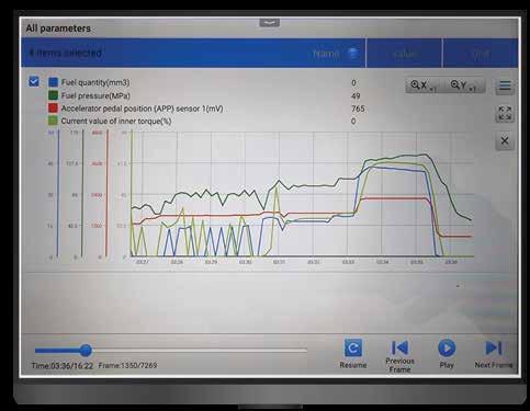
Driving the vehicle demonstrated inconsistent and random faults, from a total lack of throttle response to an increase in power delivery without any throttleinput request. There was also violent surging without warning at approximately 2000RPM (pic 2 – rapid change in desired torque and injected fuel quantity, no APP input change, engine surging violently).
The HP pump was a Bosch CP3, which has a volume valve (MPROP) controlling input volume, with a DRV mounted on the fuel rail –dual-point control. The four essential functions I chose to log using our scan tool – a maximum of five was possible – were ‘APP track 1’, ‘rail-
pressure sensor output’, ‘DRV control duty’ and ‘MPROP control duty’.
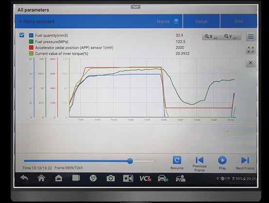
For a baseline comparison, refer to pic 3 (normal expected response to APP snap throttle), where rail pressure and torque track APP as expected.
Given the symptoms, I would have expected to see a change in PCM response due either to rail-pressure change or injector-opening duty, which takes place over three opening events. The very essence of electronic diesel control is instant PCM modulation to rail pressure from APP demand and correction when there is deviation between request and actual values. All of my observations took this into account.
Sadly, it wouldn’t be possible to publish all my data logs. I will choose the most interesting and relevant; I’m hoping you can study them in detail.
These tests were repeated several times with two different co-pilots. My most critical focus was ensuring the APP input request was not the cause of erratic performance. I will return to these logs later.
It was important for me to scope the previous four functions, allowing me to visually monitor control and response with real-time evaluation. Serial-data sampling rates have the effect of smoothing out data, which may hide critical glitches.
A perfect opportunity to understand the erratic idle was via scoping the rail-pressure sensor voltage, DRV duty (with cursors), the MPROP (disconnected as it has no function at idle; its default function is fail-open or maximum flow) and the injector-open duty (using a current clamp). This was repeated on all injectors.
Despite there being erratic idle speed and a distinctive uneven rotation speed, there was no deviation in rail pressure, DRV duty or injector-delivery period, except a minimal change at the tail of the third open event, usually a function of smooth-running correction.
I removed the APP from the floor pan to scope both tracks 1 and 2; after conducting
a full sweep several times, no glitches were found. I also found the PCM location close by the left-side A-pillar.
So what, if anything, did all of my testing establish? The diesel particulate filter (DPF) back-pressure sensor was not changing serially but functioned correctly and within spec at the sensor.
The one single serially monitored event that was inconsistent when logging during fault events – with rapid changes in value, both up and down – was engine-torque calculation. Great care was taken to avoid any change in APP input on these occasions (pic 4 – note
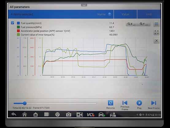
value of calculated torque increase with fuel pressure, no APP input request).
My initial conclusion was a poor software update, possibly for exhaust-gas recirculation (EGR) or a DPF delete. My opinion later changed due to the random nature of the fault. A software issue would be predictable and repeatable.
So on reflection – and this is totally against my nature – I advised replacing the PCM with a second-hand donor PCM. If it worked, OK; if not, I had missed something and needed to look deeper.
The problem is, of course, the cost versus
value. My attention was drawn to a rise in rail pressure without APP request or, more to the point, no correction to DRV duty. The PCM was not in closed-loop or was simply deaf to the problem. This would explain the unpredictable nature of the engine performance.
The vehicle is currently in the car park. Just a footnote: I did conduct a relativecompression test which returned a perfect mechanical cylinder balance. I also noted the serial injector-correction balance values were excessive given new injectors and correctly coded.

Already offering one of the largest gasket Permaseal has now expanded this further gaskets for light-commercial vehicles and cylinder-head covers for passenger vehicles.
This latest addition of light-commercial vehicle gaskets provides coverage for more than 150,000 Japanese light trucks such as Toyota Dyna, Hino, Isuzu and Mitsubishi Fuso, with more than 150 part numbers.
Full OEM cross-referencing allows the Permaseal team to find you the right product for your vehicle to get it on back on the road sooner, from service level items through to full sets.
Permaseal’s light-commercial range is backed by its trusted local team of technical experts committed to providing products that meet or exceed OEM specifications.

Backed by a fiveyear/150,000km
Permaseal provides the range, confidence and expertise to keep vehicles on the road.
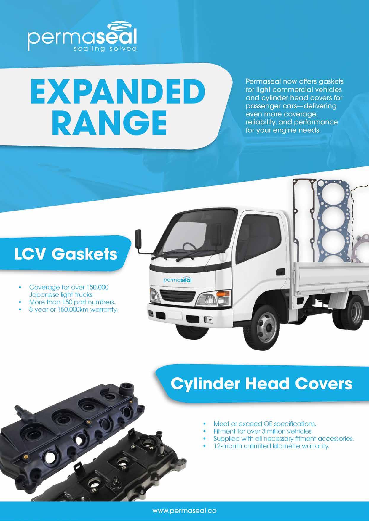
As part of its commitment to providing sealing solutions, Permaseal has added a range of cylinder-head covers to suit the most popular vehicles on the road. Over recent years, manufacturers have moved to plastic for optimisation of weight and costs. As they age, they can be prone to failure resulting in oil leaks, cracking, warping or blocked positive case ventilation (PCV) valves.
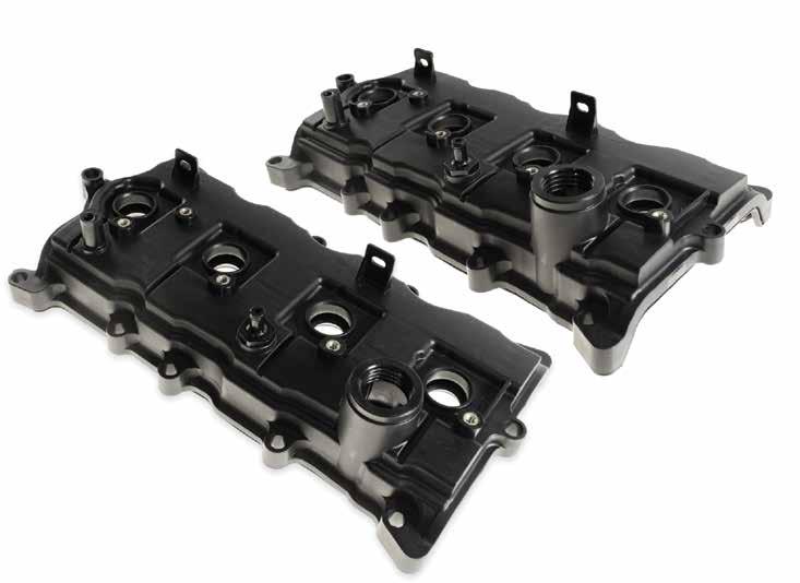
integrate components such as oil-mist separators, pressure-regulating valves, check valves or vacuum tanks.
While cylinder-head covers are crucial for sealing the engine from dirt, moisture and oil loss, the modern cylinder-head cover does more than simply forming a cover secured to the cylinder head. They often
I’ve had the privilege of meeting some amazing people during my 38-plus year journey in the automotive industry. In my time with TaT over the last 15-plus years, many very knowledgeable people have become close friends.
In June, we said goodbye to a very good friend of the TaT Tech Team, Stephen Kasapis.
Some of you may not have met Stephen. He was a very knowledgeable but humble man with a desire to learn and share that was second to none.

Permaseal’s range of 47 cylinder-head covers is made to stringent standards to meet or exceed OE specifications, ensuring correct fitment for more than three million vehicles. All covers are supplied with all necessary fitment accessories, making them a suitable replacement for the original cover and backed by a 12-month unlimited kilometre warranty.
• Find out more at www.permaseal.co

Stephen was constantly learning, sharing and attending as many training courses as possible, even travelling to the UK to learn from the best in the industry. His knowledge and ability to diagnose faults in complex systems was amazing.
I visited Stephen in hospital. He was in a lot of pain but still very grateful for the visit and loved chatting about diagnostic jobs. We even discussed the Pico waveform captures I had on my phone. He lent his ear and gave advice about some of the challenges I was facing in my business – what a great guy!
The international guest speakers at this year’s Autocare show even made sure to drop by for a visit.
Just before Stephen’s passing, he received an achievement award from the Australian Automotive Aftermarket Association (AAAA) presented by Stuart Charity at his bedside. The presentation was also attended by other industry VIPs – that’s how important he was. Stephen you will be greatly missed!
- Jason Smith
Responding to customer demand, Protex has expanded with two new twin-piston calipers for (2001-on) models, engineered to OE-level drivers who expect nothing but the best. Every Protex caliper is made to meet or surpass OEM standards, ensuring a precise fit and dependable performance right from the start. Each unit undergoes thorough pressure, performance and durability testing, giving drivers full confidence in their braking system even in the toughest conditions.
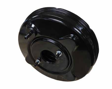
Joining the range are six new brake boosters. Compact but critical, a brake booster multiplies pedal force to deliver smooth, effortless braking, making every stop safe and controlled.
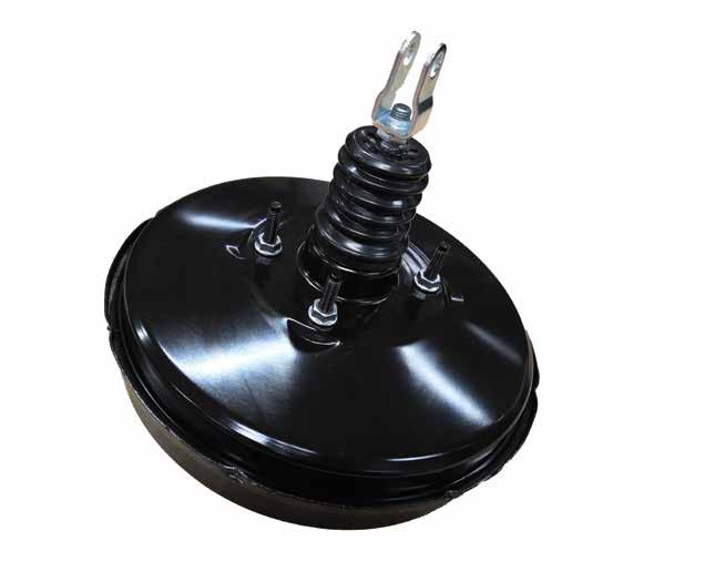
Many popular vehicles, including Toyota’s HiLux/Fortuner, Holden’s Colorado, Mitsubishi’s Triton and Nissan’s Navara, non-negotiable
Protex brake boosters
Part # To suit Year range Notes
JV1045 Toyota HiLux Workmate, Rogue, Crusade 2015-26 2.4L/2.8L diesel
JV1047 Holden Colorado DX/LX/LS/LT/LTZ/Z71 2012-20 2.5L/2.8L diesel
JV1051 Mitsubishi Triton MQ/MR 2015-26 2.4L diesel
JV1053 Nissan Navara D40 2005-15 2.5L diesel/4.0L petrol
JV1049 Hyundai i30 (FD) 2007-13 Petrol and diesel JV1052 Kia Sportage (SL), Cerato (TD) 2010-15 2.0L/2.4L petrol
Protex brake calipers
Part No To suit Year range Notes
090D0877 Nissan Nissan Patrol Y61, front left
When it comes to vehicle safety, every stop counts. Calipers and boosters are critical components in delivering smooth, secure braking and Protex is a trusted name in the automotive aftermarket for good reason. With a reputation built on high-quality, reliable brake parts, Protex continues to set standards for performance, durability and value – and these latest additions are no exception.
All Protex calipers and boosters are covered by a two-year/50,000 km warranty, giving workshops and drivers complete confidence in every stop.
• Find out more at protexparts.com.au

you like the magazine, you’ll love the website
TaT is a unique platform that provides members with practical information and solutions straight from the workshop floor. Information of the kind you won’t find in a call centre, manual or wiring diagram. Sign up at tat.net.au

TaT MAGAZINE: Australasia’s top technical automotive magazine, mailed to you six times a year, plus search 2,000+ pages of back issues online.

REPAIR SOLUTIONS: Instantly search 5,000+ expert diagnostic solutions by vehicle, symptom, or fault code.

GOOD SCAN/SCOPE DATA: Compare your results against 24,000+ verified scan and scope data uploads.


TECHNICAL ASSISTANCE: Direct support from the TaT Technical team and fellow members when you need it.

TECH TINA (AI): Instant, step-by-step diagnostic help with direct links to proven Repair solutions.

FAULT-CODE DATABASE: Access 8,000+ electronically indexed fault code definitions.
Like us on Facebook @theautomotivetechnician

Customer complaint
The car would crank but not start.
Problem summary
Spoke to the customer and they’d just purchased the car from someone who had spent thousands – I was told anywhere between $10,000 and $14,000 – trying to get it working properly.
Many components had been replaced – the injectors (unsure if all four, but at least two), suction control valve (SCV), turbocharger, fuel-rail pressure sensor, fuel-rail pressure limiting valve (PLV), crankshaft position (CKP) sensor and camshaft position sensor (CPS). All this work had been done at local workshops.
Diagnostic sequence
Carried out a cranking-cadence test and the engine sounded normal, though I did notice it didn’t sound like the injectors were even attempting to fire.
Checked for diagnostic trouble codes (DTCs) and none were present. Monitored the fuel-rail pressure – it was only getting as high as 10 megapascals (MPa) and it took a long time to get there.
Carried out a fuel-injector leak-back test and found injectors #2 and #3 were returning an excessive amount of fuel. Injector #2 returned around 20mL diesel within 15 seconds of cranking. Injector #3 returned around 10mL within 15 seconds of cranking (pic 1).
Recommended the replacement of all injectors, as well as draining both the main and sub fuel tanks and replacing the fuel filter.
Carried out these repairs, then carried out the bleed procedure for the injectors. The


car now started normally, quickly building to 30MPa.
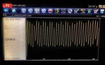
However, it now had a fluctuating idle, fluctuating between 28MPa (4110psi) and 180MPa (26,100psi, pic 2). There was also a definite diesel/injector-knock noise when the accelerator pedal was pressed. Removed the SCV and found the inner O-ring was torn (pic 3), so replaced and refitted the O-ring.
Also noticed the PLV on the end of the fuel rail had a damaged O-ring – someone had replaced it or at least removed it – so replaced that too. The PLV was extremely tight, requiring a breaker bar to unfasten.
Restarted the car and the idle was now normal and did not fluctuate – I suspect this issue was just the SCV O-ring I had replaced.
Next, road-tested the vehicle and found it lost power from around 2700RPM. It also set the code, P0089 – Fuel pressure regulator A performance.
Decided to test the PLV. Removed the banjo bolt at the end of the rail so I could connect a clear hose into a bottle for the PLV and also bypass the injector return into the rest of the return system so they were not affected.
The banjo bolt was very difficult to remove from the banjo fitting. Thought the copper washer might have crushed into the threads of the bolt but it was loose.
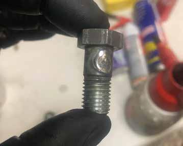
After removing the banjo bolt and fitting as an assembly, I hit the banjo fitting with a hammer to get it off the bolt – this revealed someone had welded up the holes for the banjo bolt (pic 4).
I can only speculate but suspect the thought process had been, ‘If I clamp a return hose on, say, a Falcon or older Commodore, the fuel pressure goes up and it delivers more fuel per injection in the same amount of time. This probably works the same.’
Drilled the holes back into the banjo bolt and carried out the PLV test. The PLV failed miserably, relieving fuel pressure at around 2700RPM – the same revs as when it lost power during the road test.
Based on previous experience – and a chat with Clinton Brett from Diesel Help Australia – I advised the customer to replace the entire fuel-rail assembly (with the fuel-rail pressure sensor and PLV included).
Performed that repair, bled the fuel system and tested the PLV again to be sure – there was now no relief of pressure at all when revving the engine on the spot.
However, I did spill about a litre of diesel on the floor after a rock-hard return hose cracked when I moved it about 1/50th of an inch.

I’m not sure where to start or even what the original issue was.
But to me, the original fault/s were the injectors, SCV O-ring, PRV failure and return-system tampering, which may have caused the previously replaced injectors to fail.
Replaced four injectors, the SCV O-ring and complete fuel rail, as well as drilling a hole in the banjo bolt, replacing fuel in both fuel tanks, replacing the fuel filter and bleeding the system correctly.
Diagnostic time was two and a half hours, taking into account preparation and research.
Repair time was five hours, taking into account the location of parts and carrying out the repair to a tested outcome.
This was a tricky one. Not knowing what repairs had been done was one thing but coming across welded and changed parts was another!
Repair Solution by TaT Tech Team member Gary O’Riain.
The customer said the vehicle lost power when hot, particularly after driving for 30 minutes. He said the issue had seemed to crop up following an exhaust-gas recirculation (EGR) cooler fit elsewhere. The customer said he had spent more than $10,000 chasing the fault over the last 12 months at various shops. Work had included a transmission rebuild.
Problem summary
No fault codes were stored, so roadtested the vehicle by driving it home while recording engine data during the 20-minute drive

As I approached home, I noticed the car seemed to have a little less get up and go –nothing drastic, but noticeable.
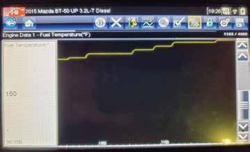
Reviewing the saved data, I noted the fuel temperature had steadily climbed throughout the whole drive, reaching 65ºC (pic 1).
I recalled hearing of a similar loss-of-power situation during long drives with a Ford PX Ranger due to the fuel pipes at the fuel filter being put on back to front.
Checked the fuel pipes on this BT-50 and they were indeed fitted incorrectly (pic 2), which I assume must have made the fuel bypass the fuel cooler.
Moved the fuel pipes to their correct positions (pic 3) and was able to drive to work the next day with fuel temperature remaining much lower.
Fault description
The fuel pipes at the fuel filter had been installed in the wrong locations.
Fault solution
Refitted the fuel pipes to their correct locations.
Recommended time
Diagnostic time was one hour, taking into account preparation and research. Repair time was about 10 minutes, taking into account the location of parts and carrying out the repair to a tested outcome.
Repair Solution by TaT Tech Team member Brendan Sorensen.

Customer complaint
The vehicle – a KDJ150R model with 349,483km on the clock – had the anti-lock braking system (ABS), traction control and check-engine light (CEL) warnings showing on the dash.
The previous repairer had erased codes several times but the warning lights kept returning.
The ABS control module had been replaced in an attempt to solve the problem.
Problem summary
Verified the warning lights were showing on the dash during a road test and in the workshop.
Diagnostic sequence
Started with usual diagnostic tests: battery tests, all lights and charging-system operation.
Conducted a full electronic scan and several fault codes were present in the ABS module:
• C0226 – SFR solenoid circuit.
• C0236 – SFL solenoid circuit.
• C0246 – SRR solenoid circuit.
• C1225 – SA1 solenoid circuit.
• C1227 – SA3 solenoid circuit.
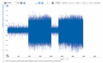
Decided to focus attention on the ABS control module. Load-tested the main power and ground circuits with an oscilloscope and noticed an unusual amount of noise on the main, thick ground circuit with the engine running – approximately 2V AC noise peak to peak.
Was initially a bit puzzled because the circuit had tested fine with key-on/engine-off (KOEO).
After some tinkering around, verified the noise was present with the low-beam headlights on – because the lights were set to ‘auto’, they came on when the engine was started each time.
When the headlights were switched off, the noise reduced to approximately 0.25V (pic 1).
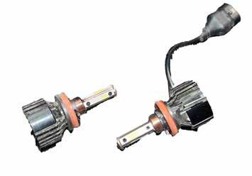
Inspected the headlights and found new, cheap LED headlight globes (pic 2).
Disconnected the LED globes and fitted standard halogen globes to retest. The excessive AC ripple on the ground circuits
Erased all codes and extensive road testing verified the problem was solved.
Fault description
Replacement LED headlight globes were back-feeding AC ripple into the vehicle’s ground circuit.
Fault solution
Refitted standard halogen headlight globes and the fault was resolved.
Recommended time
Diagnostic time was two hours, taking into account preparation and research. Repair time was 30 minutes, taking into account the location of parts and carrying out the repair to a tested outcome.
Repair Solution by TaT Tech Team member Marty Hosie.
Customer complaint
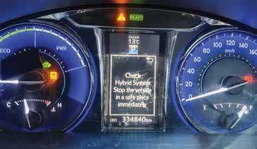
The ‘Check hybrid system’ (pic 1) and ‘Charging system malfunction’ (pic 2) warnings were illuminated in the vehicle’s instrument cluster and braking power was reduced.
Another workshop had already fitted a second-hand inverter/converter assembly but this had not fixed the problem.
Problem summary
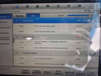
Confirmed the warning messages, while a full vehicle scan retrieved the following fault codes (pic 3):
Hybrid system
• P0A08 – DC/DC converter status circuit. Anti-lock braking system (ABS)
• C1336 – Zero point calibration of deceleration sensor not performed.
• C1345 – Linear solenoid valve offset learning not performed.
There were also a handful of communicationtype codes in various modules that were a knock-on effect of the core fault.
Diagnostic sequence
Cleared the fault codes to determine what returned. With ignition on, found the only code that didn’t clear was C1345. All warning messages had disappeared from the cluster. Used my Autel’s ABS special functions mode to carry out a linear solenoid-valve offset learn procedure, which buzzed several valves and flashed certain cluster lights over the course of a minute. At the completion of the procedure, the code cleared.
With the vehicle in ‘Ready’ mode, I still had no fault codes and full braking power had returned.
Road-tested the vehicle and after approximately one minute the warning lights came back, along with the P0A08 code.

Tested the 12V battery in the boot, which was in good condition having obviously been recently replaced.
Cleared the fault code again and noted the 12V battery was charging at 14.2V when in Ready mode. Then after approximately one minute with the vehicle at a standstill – still in Ready mode – the P0A08 set again and the battery started charging at 14.6V.
Repeated this process a couple of times, each time seeing nothing aside from charging voltage from the DC/DC converter change in scan-tool data at the moment the code set, like clockwork.
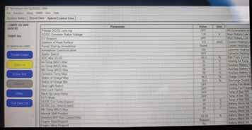
The DC/DC converter temp was reasonable at 28ºC and the DC/DC converter target pulse duty of 66.5 per cent at 14.2V was similar to a known good on TaT and increased to 73.7 per cent at 14. 6V.
I did notice the data parameter ID (PID) ‘DC/DC converter status voltage’ at 1.91V (pic 4). The known goods on TaT did not show this PID.
Brought out a Toyota Techstream scan tool. It read the same P0A080 code but the data PID ‘detail code’ read 264. This subcode meant the full code was P0A080:264. Using a Toyota data subscription, I looked up the fault tree for this code, which called for checking several fuses to confirm the inverter/converter cooling system was operational, then performing some wiring checks from the converter to the control module.
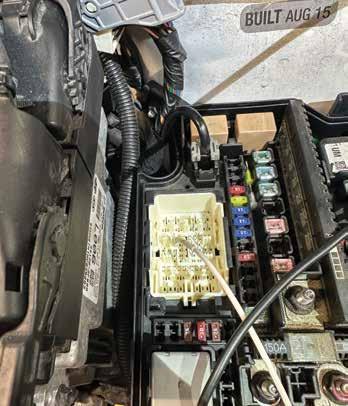
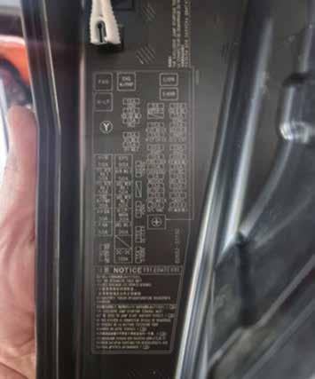
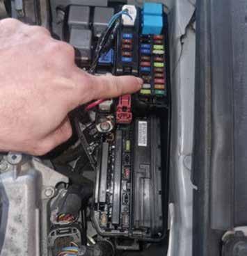
While a section in the service information gave descriptions for all data PIDs, neither this nor the fault tree mentioned anything about DC/DC converter status voltage. Decided to check all fuses, starting in the underbonnet fuse box with a test light. Out of habit, I checked the labelling on any missing fuses and – to my surprise – the third fuse holder up on the left was missing and it was labelled DC/DC-S (pic 5).

Inserted a 7.5A fuse (pic 6) and noticed the data PID DC/DC converter status voltage changed to 3.83V.
Cleared the fault code and found the car could now sit in Ready mode indefinitely, charging at 14.2V. The fault was fixed.
Fault description
The DC/DC-S fuse was missing from the underbonnet fuse box.
Fault solution
Replaced the DC/DC-S fuse.
Recommended time
Diagnostic time was 90 minutes, taking into account preparation and research. Repair time was about five minutes, taking into account the location of parts and carrying out the repair to a tested outcome.
Repair Solution by TaT Teach Team member Brendan Sorensen.
Customer complaint
The traction-control warning light was intermittently illuminating, along with the messages ‘Service ESC’ and ‘Service 4WD’ in the instrument centre cluster screen.
Problem summary
Noted no warning messages or lights on initial start-up. However, while sitting with the ignition on during the code scan, the Service ESC and Service 4WD messages popped up.
Diagnostic sequence
A full scan of the vehicles revealed the following fault codes:
Anti-lock braking system (ABS)
• U0102 – Lost communication with transfer case control module invalid serial data received (symptom 71).
Body control module (BCM)
• B1517 – Battery voltage plausibility failure (symptom 5A).
• U0159 – Lost communication with parking assist control module (symptom 00).
Transfer-case module
• B2725 – Transfer case range selection switch circuit signal invalid (symptom 08). History DTC, test not passed since power up.
Retrieved the freeze-frame for the transfercase code B2725, which showed range actuator position 96 degrees and in two-wheel-drive (2WD) mode. The rangeselection switch showed 1.76V.
Cleared all fault codes and only U0102 and B1517 did not clear.
Tip: In the past, I’ve had other GM vehicles that won’t clear ABS codes with a full vehicle code clear. Rather you have to go into the specific ABS module to clear them.
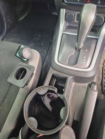
Looking at the transfer-case module’s live data for the range-selection switch – the dial in the centre console used to choose transfer-case position – I noted that it was correctly reporting I was in 2WD mode but the voltage was fluctuating around 1.9V to 2V.
During a road test, I noted the voltage would continue to fluctuate. Going over bumps it


could drop below 1.7V, which would change the data PID from 2WD to inactive.
It was definitely a fault, however the glitches mustn’t have lasted long enough as they produced no additional codes and no warning lights.
While stationary, I found wiggling the rangeselection switch could make the data PID fluctuate erratically all the way down to 1.74V despite still physically being in the 2WD position.
Given the live data had lots of other helpful information – including that the transfercase range-selection switch reference voltage should always stay at 5V – it was obvious the fault was inside this switch itself (pic 1).
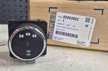
The switch pulled out of the centre console easily. I stripped it down slightly but it was too flimsy to clean properly and a replacement was only about $100 new (pic 2).
Fault description
A faulty contact in the range-selection switch.
Fault solution
Fitted a new range-selection switch (pic 3).
Recommended time
Diagnostic time was one hour, taking into account preparation and research. Repair time was 30 minutes, taking into account the location of parts and carrying out the repair to a tested outcome.
Good readings for the range-selection switch are: 2WD = 2V, 4WD high = 3V, 4WD low = 1.5V. It appears the module doesn’t
know what position you are requesting if the tolerance is 100 millivolts (mV) outside of these ranges.
Repair Solution provided by TaT Tech Team member Brendan Sorensen
Share a solution to earn reward points tat.net.au/tat-share

The vehicle
Subaru XV GP7, built 11/2015, FB20 2.0-litre engine, 76,000km on the clock, continuously variable transmission (CVT).
The complaint
This was the first time I had seen this vehicle as it had recently been purchased. It was also a first-time customer – they’d booked the car in for a service. They were unaware of any problems and had not mentioned any issues at the time of booking.
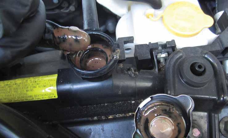
During my normal service checks I discovered some unusual things. The engine and bell-housing bolts had been tampered with, with wreckers texta markings on some components. Alarmingly, I discovered an oily substance underneath the cooling-system radiator cap. This oily substance was also at the top of the radiator filler neck and in the cooling-system recovery bottle. I could not 100 per cent identify whether it was engine oil or transmission (CVT) fluid (pic 1). I immediately pressure-tested the cooling system, which indicated no pressure loss and there were no visible signs of external leaks. I obviously also checked the engine oil level and colour for contamination – they appeared OK.
At this point, and before I called the
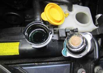

customer, I did a little bit of research to see if there were any known faults, fixes, technical service bulletins (TSBs) or TaTassists for Subarus with cooling-system issues.
Alarmingly, I found three common issues with this particular Subaru engine:
1. A two-port plastic positive crankcase ventilation (PCV) fitting at the top of the engine can leak via the two O-rings that are supposed to seal it.
2. Internal transmission-cooler leak problems between the cooling system and the transmission.
3. Engine-block sealing O-rings deep inside the engine can fail.
I called the customer with the information
I’d sourced so far and a request to do some diagnostics to ascertain where the source of the contamination may be coming from. He agreed to some diagnostics but as far as he was concerned, the car didn’t have a problem – it was running fine.
I got the impression he didn’t comprehend the potential seriousness of the situation that was unfolding. I cautiously moved on with the job.
Next, I performed a cylinder-head gasket test using a simple Tee-Kay tester as a preliminary check, then with a pressure-pulse sensor with the PicoScope looking for any combustion or cylinder events in the cooling system – none were found.
I’d already checked the transmission fluid for level, quality and contamination – it was OK, much like the engine oil I’d already been checked.
I contacted the customer again but with no hard evidence of where the oil may be coming from. He wasn’t keen to spend more money, so we set in place a minimum plan which included inspecting and replacing the PCV fitting at the top of the engine as it was an easy, non-invasive job and not very costly. We would then clean the top of the cooling system, including the recovery bottle, and
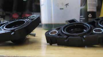
bleed the cooling system before returning the vehicle for him to drive for a week before reinspection.
I also mentioned the possibility of removing the transmission-oil cooler to pressure-test it. I said bench-testing components was not foolproof; temperatures that may normally cause a part to fail may not be met, which may lead to an unsatisfactory test. The customer made it clear he didn’t want to spend the money on testing anyway.
I replaced the PCV fitting and, on inspection, found the O-rings that seal the PCV housing to the engine block were flattened, though there was no hard evidence that may have led to a leak between the PCV system and the cooling system (pic 2). Next, I cleaned the cooling system, including the recovery bottle, though it was not a full system flush as the contamination appeared to be only around the radiator filler and recovery bottle.
Refilled the cooling system with coolant, then bled the system, road-tested the car and returned it to the owner. I left a sample of the oil that had been removed from the cooling system in a cup overnight to see if it could be identified after it had time to settle and hopefully separate from the coolant. Once again, I could not 100 per cent identify whether it was engine oil or CVT fluid.
One week later, the owner returned the car for inspection. I inspected the cooling system and there was no notable oily residue on the radiator cap. I once again warned them that while nothing significant was found, there could be other underlying issues that may develop in the future. He decided to drive on
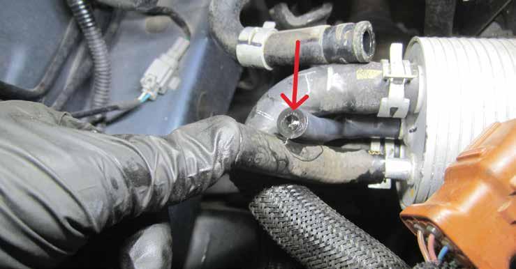
because as far as he was concerned, there were no driveability issues.
Fast forward eight months and 13,000km and the vehicle arrived again for service.
On inspection of the cooling system, I once again found a small amount of oily residue on the radiator cap, filler neck and in the recovery bottle – though not as much as eight months earlier (pic 3). The top radiator hose was oil-contaminated and had become soft, so replaced it.
Once again, I cleaned the cooling system and corrected the level. Service completed, I sent the car on its way again with warnings of potential further problems.
Fast forward another three months and 3000km and customer returns the vehicle reporting a steering problem. I road-tested
the car with them and heared what seemed to be a bad rear-differential clunk. After further inspection on the hoist, I discovered a large oil stain coming from the coolingsystem recovery bottle and spraying all underneath the car all the way to the back and onto the tailgate.
I lowered the car from the hoist, removed the radiator cap (when cool) and found lots of oil in the cooling system which was overflowing into the recovery bottle (pic 4). Checked the engine oil and found it was at the correct level and colour.
Raised the car on the hoist again and found the front and rear diffs were basically functioning OK – no notches or clunks were experienced during the road test.
The suspect component was the centre diff in the transmission. I then checked the transmission fluid and found it was 1.7 litres low, though the colour and the quality appeared OK and there were no signs of coolant contamination. I suspected the transmission cooler could be the issue.
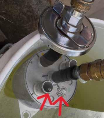
With the transmission cooler still installed in the vehicle, I removed the oil hoses and put them in a raised position, then pressuretested the cooling system, which led to very small bubbles coming from the disconnected transmission-cooler oil pipes (pic 5).
Contacted the customer to gain a financial commitment for further diagnostics. Removed the transmission cooler from the vehicle, then set up a test rig to pressure-test the suspect cooler. Submersed the cooler in a bucket of water, forced air under pressure into the cooler and could see bubbles slowly starting to escape from the oil chamber and clearly coming from the transmission cooler (pic 6).
Armed with this evidence, I contacted the owner to confirm the transmission cooler was
indeed faulty and would need to be replaced. I also explained the transmission/centre-diff problem would need to be investigated. I said the transmission fluid had been 1.7 litres low and there was a small chance the low fluid level could be the problem, so further testing would be required.
The new transmission cooler would take a couple of days to arrive on order from interstate. However, even after explaining all of this to the owner, I received a text 20 minutes later asking if he could pick up his car that night. At this point I realised he had not really comprehended anything I’d told him, so I involved his wife in the communication and decision-making; she’d been a customer for a long time and was very good at listening, comprehending and making decisions.
While waiting for the new transmission cooler to arrive, I looped both the oil and coolant hoses together so the vehicle could be run and the car could still be worked on.
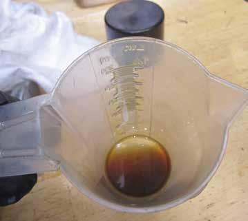
I also thoroughly flushed the cooling system using a product from Natrad called Oil Stripper 2. Following the instructions closely, I flushed the cooling system five times, leaving it totally clean and free of any oily residue. I also drained the transmission fluid into a clear container where it could be visually checked for coolant contamination – no contamination was present (pic 7) – then refilled the transmission fluid and performed a short road test. After draining the fluid and closely inspecting, I found no signs of contamination.
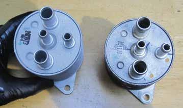
The new transmission cooler finally arrived and was installed into the vehicle (pic 8). I then refilled and bled the cooling system following correct procedures before filling the transmission fluid to the correct level, also following the correct procedures and adding a treatment product to the fluid.
I then road-tested the vehicle. The cooling system was functioning correctly and no oil was present in the cooling system. The transmission/centre-diff problem showed a huge improvement but there was still small evidence of an infrequent clunk.
I suspect some moisture had entered the transmission, possibly affecting some of the friction material and causing further issues. I discussed this with the owner, who decided to take the vehicle and drive it to see how the issue would develop. He traded the car shortly thereafter.
Although this case study focuses on a cooling-system fault, it once again highlights the need to have good communication skills with customers. While I believe I’m good at this kind of thing, this customer was very difficult to communicate with and never did seem to take in what I was saying. I’d even sent pictures and videos with descriptions as the job had progressed.
Happy diagnosing!

Does changing the DC pulse width also change the frequency of emulated sine waveform? And are frequency, RPM, cycles, Hz and wavelength all the same?
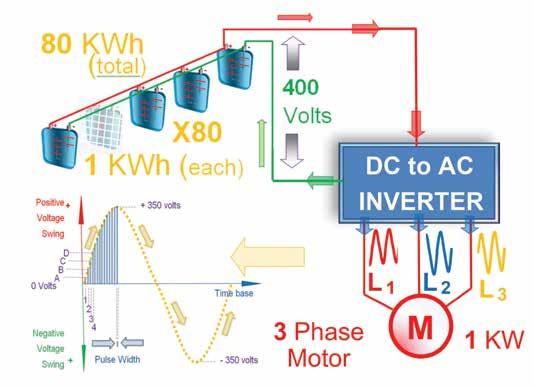
In our previous article we explored one of the many ways how the inverter of an electric vehicle (EV) generates alternating current (AC) from a direct current (DC) source – such as the vehicle’s highvoltage battery – by incrementally pulsing the output voltage (pic 1, blue trace) to emulate a sine wave (pic 1, yellow trace).
Power-electronics engineers have effectively transformed (or made available) the 80kW of DC power from the battery pack into a usable three-phase AC supply – delivered in a ‘pulsed’ form to the motor. By increasing and decreasing the pulse voltage in a sinusoidal manner, a pseudo sine waveform is created to power the load (i.e. the three-phase electric motor).
By the way, have you noticed the three input wires to the threephase 1kW motor (pic 1, red) are not only labelled as inductors ‘L1’, ‘L2’ and ‘L3’ (red, blue and orange) but the sine waves are ‘out of phase’ to each other? That’s an essential ingredient for three-phase motors, but more on that later.
For now, and before we get into how changing pulse width affects waveform frequency, let’s revise the core concepts from a mechanic’s point of view (MPOV) and build a common understanding of the technical terms and acronyms that hybrid and EV technology have introduced.
RPM – Revolutions per minute
We’re all familiar with RPM as a measure of how fast something –say, an engine crankshaft or an EV motor shaft – rotates. It tells us how many revolutions occur per minute (i.e. every 60 seconds). From the MPOV, it simply measures how many full turns a shaft
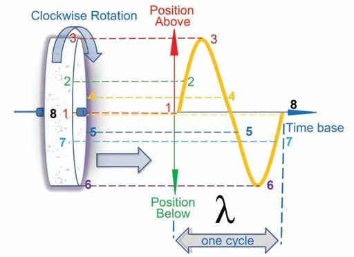

makes in one minute, be it from a three-phase motor and/or a crankshaft. But if we were to plot the motion of that rotating shaft over time, it would trace out a waveform resembling a sine wave.
Example (pic 2):
1. Suppose the shaft starts at the 9 o’clock position (labelled ‘1’).
2. As it rotates to 10 o’clock (labelled ‘2’), then through to ‘3’ through ‘8’…
3. We plot these positions along a time axis (X-Y graph).
4. The result is a complete cycle – a waveform that visually resembles a sine wave.
Therefore, one mechanical revolution equals one sine-wave cycle –at least in a diagrammatic sense.
Hz, frequency and cycles per second
Let’s now relate RPM to frequency, which is measured in Hertz (Hz). Imagine an engine running at 3000RPM:
1. Divide by 60 (seconds per minute): = 3,000 ÷ 60 = 50 cycles per second.
2. So 3000RPM = 50Hz.
This aligns with standard AC frequency in Australia, where power points operate at 50Hz. Hence, RPM, cycles per second and frequency are interchangeable, depending on context.
Wavelength (λ – lambda) and RPM
Another key concept is wavelength, represented by the Greek letter λ (lambda). From a waveform perspective, it answers the question:

How long (in time or distance) does one complete cycle take?
For example:
At 3000RPM or 50 cycles per second…
· Each cycle lasts:
= 1 ÷ 50 = 0.02 seconds = 20 milliseconds (ms).
So the wavelength in this context is 20ms per cycle. It’s a temporal wavelength but spatial wavelength (distance per cycle) peak-topeak or trough-to-trough can also be relevant, especially in signal propagation or motor windings (more on that later).
Sine-wave patterns – AC vs DC
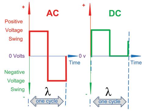
From the MPOV or electrical standpoint, a true sine wave oscillates above and below a central reference line (zero volts), as seen in pic 3:
• Red waveform (AC) swings both ways – therefore the current alternates direction (alternating current [AC]).
• A waveform entirely above the centre line (pic 3, green) is a direct current (DC) signal – it flows in only one direction.
Sensors such as magnetic crankshaft position (CKP) sensors generate pure sine waves (AC). Others, including oxygen (O2) sensors, may oscillate above the centre line – technically still a wave, but not classified as DC.
Important note: Whether a waveform is AC or DC depends on how it’s positioned relative to the zero reference. However, frequency and wavelength remain defined the same for both.
Square-wave patterns – AC and DC
Another familiar waveform is the square wave (pic 4, green and red).
While it shares many of the same attributes as sine waves – frequency (Hz), wavelength (λ), RMS values, etc – the on/off nature introduces a unique measure, duty cycle.
In EVs and internal combustion engine (ICEs) vehicles, square waves are common in:
• Sensor outputs (e.g. Hall effect sensors on camshafts – pic 4, green).
• Trigger signals (e.g. from ECUs to solenoids or relays).
If it’s a trigger signal (such as from the ECU to a/c solenoid), then the on and off times (pic 5A – brown arrows) become critical. This timing is what we call pulse-width modulation (PWM).
DC pulse-width modulated square waves
In PWM signals, a square wave is modified by varying its on time (pulse width) while keeping the same frequency (pic 5B and 5C –brown arrows).
This is the core principle used by inverters to build sine-wave-like voltages. Instead of a continuous analogue signal, they deliver bursts of voltage with controlled width and spacing so the average voltage over time traces the shape of a sine wave.

Pic 5D1 and 5D2 show how different stages of square waves combine to form this sinusoidal pulse-width modulated (SPWM) wave pattern, employed in EV/hybrid cars.
While OEMs use a variety of other techniques to control the speed and torque of AC motors, SPWM (i.e. varying the pulse width – pic 5D1) allows control over amplitude and changing the reference sine frequency controls motor speed. This efficiently controls torque and speed on three-phase AC motors.
In summary
From the MPOV, DC PWM is used in EVs to mimic sine waveforms, enabling inverters to change DC battery power into AC to drive electric motors.
Here, we’ve clarified key terms such as RPM, Hertz and wavelength and explained how square wave pulses can be shaped to emulate sine waves – hence the term SPWM.
Changing the pulse width primarily alters amplitude (torque); the fundamental frequency is set by the reference sine and determines motor speed.
By skilfully manipulating both amplitude and pulse width, powerelectronics engineers deliver precise torque and instant acceleration – hallmarks of EV performance.
Until next time
While EVs use high-voltage DC from their main battery packs to generate AC power for driving the electric motor (via inverters), do they still have traditional 12V (or 24V) batteries under the bonnet?
And if so, why do EVs still require a jump start when this low-voltage battery goes flat?
After all, there’s no starter motor in an EV – so, and this is just a teaser, what’s the purpose of the jump start?
Safety warning: These articles aim to improve understanding of EV electrical systems using simplified theory and practical insight. However, readers must be warned – contact with high voltage is lethal. If you intend to test or work on high-voltage (HV) systems:
• Use CAT IV-rated tools (e.g. digital multimeters [DMMs]).
• Wear insulated gloves and personal protective equipment (PPE).
• Follow industry de-powering protocols.
• Work only after completing certified HV training.
• For more information, check out TaT’s EV training resources at tat.net.au/scandata/classes/webinar/main_template.php
The workshop is humming, the phone is ringing off the hook and a tricky diagnostic job lands in your bay, threatening to throw the entire day into disarray.
In these moments, having a clear diagnostic process is crucial but sometimes even the best of us can lose our path when the usual tests don’t yield the expected results. But what if you had an assistant who not only helped guide your process but also offered instant access to a vast library of known good data and confirmed fixes?
Meet Tech Tina v3. Our artificial intelligence (AI) powered assistant has received her most significant upgrade yet, making her an even more indispensable tool for TaT members.
A quick refresher: Who is Tech Tina?
For our newer members, Tech Tina is our dedicated AI assistant, designed to help TaT members with vehicle information, diagnostic troubleshooting and repair guidance. She is the sister of our other AI, Tech Tony, and her primary focus is to provide fast and accurate answers to your vehicle-related questions, saving you valuable time and streamlining your workflow.
Tech Tina combines advanced AI capabilities with highly specialised automotive training. Her knowledge base includes detailed, industry-specific instructions tailored explicitly for automotive diagnostics and repair scenarios. This specialised training enables Tina to understand technical language, common workshop scenarios and automotive terminology, providing you with precise and actionable information.
To get the best results, you need to provide Tina with as much detail as possible. Think of it like booking a car in with another technician; you wouldn’t just say, ’It’s running rough.’ You’d provide the make, model, year, engine and fuel type, along with any symptoms, fault codes and testing performed or parts you may have already replaced.
The more specific your query, the better Tina can narrow down the possibilities and provide the most accurate guidance.
While the core of Tina remains the same, v3 represents a monumental leap forward in her capabilities. We have integrated Tech Tina directly into TaT’s most valuable resources, transforming her from a knowledgeable assistant into a data-powered diagnostic partner.
Tina now has direct access to TaT’s extensive database of Repair Solutions, scan data and technical-video archives. This integration means she can instantly cross-reference your query with thousands of verified repairs, known good scan-tool data, fault-code diagnostics and proven fixes.
By accessing these resources, Tina provides even smarter, more precise diagnostic guidance and detailed repair strategies based on real-world case studies, significantly enhancing her accuracy and efficiency.
Putting v3 into practice
Let’s walk through a common scenario. A vehicle presents with a lack of power, and your initial wide-open throttle (WOT) oxygen (O2) sensor test shows the sensors staying rich, telling you the issue isn’t a lack of fuel. Your next thought might be a restricted exhaust.

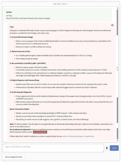
With v3, your workflow could look like this:
1. You ask Tina: ‘How do I test for a restricted exhaust using a vacuum gauge?’
2. Tina responds, explaining the test procedure: ‘A healthy engine should show a steady vacuum between 18-22 inches of mercury (inHg) at idle. When you increase RPM to around 2500 and hold it, the vacuum on a vehicle with a restricted exhaust will slowly fall towards zero.’
3. You ask for a visual: ‘Do you have a video showing this test?’
4. Tina provides the link to the TaT video.
5. After confirm the fault, performing the test and verifying the restriction, you ask: ‘What are the common causes of a restricted exhaust on this model?’
6. Tina provides a solution after searching the repair database and might report: ‘Collapsed catalytic converter monoliths are a common issue on this model, leading to a restricted exhaust.’
In just a handful of steps, you have moved from a symptom to a confident diagnosis and likely repair.
A valuable tool, used correctly
As powerful as v3 is, it’s important to remember Tina’s purpose and limitations. She is designed to assist, not replace, the skilled technician. While her knowledge base is now vastly larger, it’s still wise to compare her data against factory information if you’re in any doubt. She cannot provide wiring diagrams, pinouts, or other copyrighted materials; for those, you’ll still need to use the OEM Info Resource.
Tech Tina v3 is a powerful evolution, designed to integrate seamlessly into your diagnostic routine. By leveraging TaT’s collective knowledge of scan data, videos and real-world repairs, she is ready to help you solve problems faster and more efficiently than ever before.
• Try the new and improved Tech Tina today at tat.net.au/scandata/aiteam/techtina.php
Mackay Australia’s ever-expanding range now includes some new stable mates – wheel hubs, wheel-bearing kits and drive belts.
As with any product bearing the wellknown Mackay brand, these ranges have undergone thorough durability testing to ensure they are fit for purpose.
Mackay drive belts are made using reinforced high-quality EPDM compounds to ensure long service life, quiet operation and excellent wear resistance.
The range includes both V type (11A, 13A) type (PK) belts.
sizes and lengths ensures coverage of Australia’s diverse car park.
Mackay wheel hubs and wheel-bearing kits use industry-proven high-quality bearings,
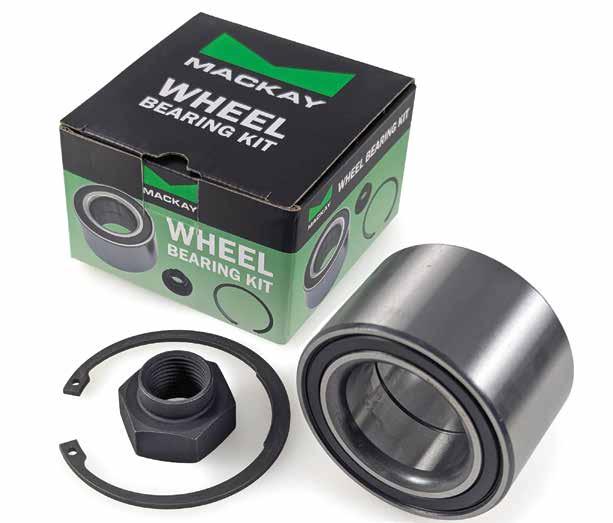
duty seals and OEM-grade anti-lock braking
where applicable. The raceways undergo multi-stage grinding and superfinishing processes, providing the foundation for durable and quiet bearing operation.
The sealed bearings use high-performance, industry-leading lubricating
grease, ensuring a protective film on rolling contact surfaces, which is essential for long service life.
The bearing kits include the seals, gaskets and circlips required to get
One hundred per cent Australian owned, Mackay has been supplying quality parts to both OEM production lines and the auto-aftermarket industry since 1932. This industry experience guarantees quality, durability and cost-effective product solutions you can rely on.
With more new ranges in the pipeline, Mackay is committed to meeting the industry’s parts needs.
• To find out more, go to mackayrubber.com.au/automotive

Repairyis a Melbourne-built scheduling platform that aims to let workshops, in its words, ‘deliver their magic’ by removing the friction between customers finding you, actually turning up, having a great experience and, importantly, telling others about it.
After trialling it within the TaT Technical Team, I found Repairy to be a tidy, practical tool for getting more bookings with less phone tennis, keeping customers on schedule and informed and turning finished jobs into public reviews.
What Repairy actually does
At its heart, Repairy gives you a clean, customisable online booking page that runs 24/7. Existing and new customers can choose a service, pick a time and land straight in your calendar. The booking flow is sensibly constrained by the rules you set. You control which services can be booked online, caps per day, lead times, buffers, closed periods and technician availability. That means you can protect diagnostic slots, avoid landing three tyreand-alignment jobs at once and block out the late Friday rush that always ends in overtime.
The system then works to keep the customer informed for you and gives both parties a great sense of control. Links can be provided to the customer via SMS and email, so they can recheck their booking or reschedule themselves when life happens – this all happens behind the scenes while
updating your calendar rather than tying up your reception phones. SMS and email reminders follow and, of course, Repairy handles follow-up so you can build your allimportant reviews repertoire.
Repairy cites big reductions in no-shows when automated reminders are used. In our hands, the automation reduced manual follow-ups because the system quietly does the nudging for you.
One of the standouts is the Google Business Profile connection. If you switch it on, customers who find you on ‘Search’ or ‘Maps’ see a ‘Book Online’ button and can reserve a slot without ever calling.
For busy front counters, this is gold. You still set the guardrails, so you are not handing the keys to the internet. You are simply catching intent at the moment the customer is ready to act.
Setup is quick if you already have a clear idea of your services and calendar rules.
On the integration front, Repairy integrates with the Marlin shop-management platform. Scott from the TaT Tech Team, meanwhile, connected Repairy to Mechanic Desk (MD) at his diagnostics-only workshop. With a couple of hurdles regarding synching of analytical data that were sorted by the Repairy assistance team, he had data flowing and appointments syncing.
Information flows two ways, so any booking made through Repairy lands in Repairy and MD and vice versa. The same is true with

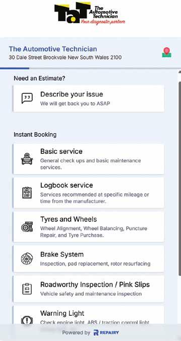
An intuitive online booking experience for customers, even right from their phone.
the customer database – update one and the other mirrors it.
Scott’s take was Repairy will really shine in general repair and tyre shops where the daily car count is higher, while a niche diagnostics outfit still benefits from the automation but feels less of the step change. I agree with that assessment.
Once configured, the calendar view is the natural hub. You can drag and drop bookings, apply quick blocks for training or parts delays and create internal-only appointment types that never appear on the public page.
One benefit over MD, which only allows you to cap hours booked per day, is Repairy also allows you to cap types of job per day. Only want one timing-belt job per day? No problem. Staff can add notes for special tools or parts to order and you can tag customers who need a loan car or early drop-off so the front counter is not caught short.
Where Repairy differs from a few marketplace-style models is ownership and control. Repairy does not take a slice of your job profit, dictate terms or pricing or hold your customers’ information hostage. It is a tool you use to attract work, schedule it on your terms and communicate under your brand. That will matter to a lot of independent workshops.

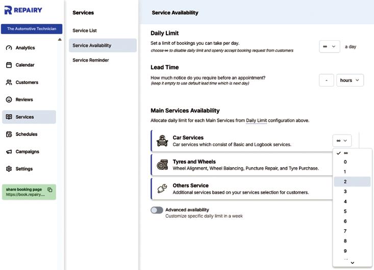
Another quiet achiever is review generation. After the job, customers receive a friendly request to rate their experience. Positive reviews help you rank locally and build social proof.
More importantly, you start a loop of reminders and rebooking prompts that keep regular services on time.
None of this is particularly new but it is exactly the sort of reliable process that reduces gaps in the diary and builds a cohort of loyal customers.
AI phone assistant in beta
Repairy is currently behind the scenes testing an artificial intelligence (AI) phone assistant that you can preload with your workshop’s instructions and common questions and answers.
I had a conversation with the beta and it handled basic queries and rescheduling with an alarmingly natural, human tone. It left me thinking, we really are living in the future. This is not replacing your front counter but it’s definitely taking the load off by handling those mundane task-based calls. It is a way to stop missed calls turning into missed opportunities, especially after hours or during the lunch rush. It will be interesting to see when this technology gets released out of beta, along with a range of other improvements Repairy is working on.
Repairy reports more than 30 Australian brands using the platform, including some large franchises, giving more than 2000 active users in total.
It is built locally, which shows in the language, the support experience and the sensible defaults. The interface is clean and nonthreatening for staff who are not particularly tech savvy. That matters, because any system you have to push uphill will be abandoned by Friday.
Repairy runs on a subscription model. There is no per-booking sting and no percentage clipped off your invoice.
For a workshop, the real cost is the hour or two it takes to define sensible services, capacities and rules. Do that once and the system does a lot of little jobs for you, day after day, quickly offsetting the cost with time saved in labour.
Repairy is not trying to be your full workshopmanagement system. It is a specialised layer for your tech stack to handle online bookings, smart scheduling and customer comms that does exactly what most of us have been trying to hack together for years. It will not fix poor processes or make a slow day busy by itself. Used properly, it clears the noise so your team can get on with delivering the magic under the bonnet.
If you want to see it in action, watch my short demo video that accompanies this review, then have a chat with the Repairy team about your specific workflow. For many shops, the combination of less phone time, fewer no-shows and more reviews will be enough reason to give it a run.
• Scan the QR code to watch my detailed video review.
- Brendan Sorensen

Century’s next-generation Lithium Pro Gen 2 batteries have arrived, delivering the same proven performance trusted by auto electricians and 12V specialists across Australia but with even greater efficiency and smarter power management.
Built using lithium-iron phosphate (LiFePO4) technology, the new Lithium Pro Gen 2 delivers the same 3000-plus cycles at 80 per cent depth of discharge (DoD) as its predecessor, meaning a significantly longer service life and more usable energy than conventional lead-acid batteries. Thanks to its superior energy density and high recharge efficiency, the Lithium Pro Gen 2 also reduces system size requirements and provides up to 10 times faster recharge times, making it ideal for deep-cycle use in caravans, camper trailers, motorhomes, 4x4s, and marine dual-battery setups.
One of the key improvements of Gen 2 is its

reduced weight – it’s lighter than earlier models and nearly half the weight of the comparable Century N70T flooded deepcycle battery (12.6kg versus 25.1kg). This means greater flexibility for weightrestricted or gross vehicle mass (GVM) limited setups. The smaller, lighter design also simplifies installation, especially with multi-angle fitment and compatibility with M8 terminal threads.
Lithium Pro Gen 2 also introduces a low power-consumption mode (LPCM), a clever feature designed to reduce self-discharge by automatically limiting energy draw after 72 hours of inactivity. It’s ideal for situations where the battery may sit unused for long
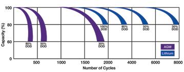
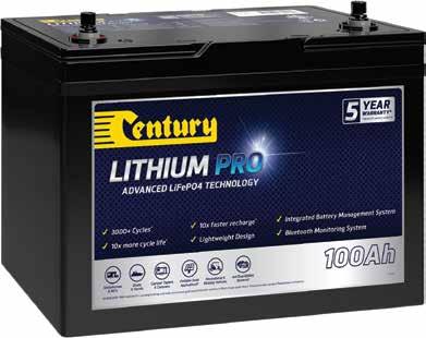
periods, helping to preserve capacity and extend its lifespan.
Safety and monitoring remain at the forefront. The advanced batterymanagement system (BMS) guards against overcharging, over-discharge and short circuits, while Bluetooth connectivity enables real-time monitoring of charge level, capacity, voltage, current, temperature and cycle count – all from a smart device.
The Lithium Pro Gen 2 is designed for tough Australian conditions and features an IP65-rated case that provides better protection against water and dust ingress, a flame-retardant ABS enclosure and wide compatibility with solar, DC-DC and smart lithium chargers, including the latest Century 25A battery charger (CC1225-XLi).
The Lithium Pro Gen 2 has been tested to

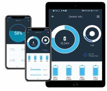
meet and surpass key international safety and performance standards – including UN38.3, IEC62619, IEC61960 and AS/NZS CISPR 32 – and is fully compliant with Australian and New Zealand regulations.
Choosing to stock and sell Century Lithium Pro batteries means workshops can also benefit from Century Yuasa’s network of 34 distribution centres nationwide, ensuring a steady supply of stock locally to support your business and serve your customers.
Century’s comprehensive nationwide warranty guarantees that, no matter where your customers are, they’ll have access to support and assistance locally if needed.
• To find out more, contact your local Century Batteries rep on 1300 362 287 or go to centurybatteries.com
A customer’s 2011 Ford SZ Territory with 210,052km on the odometer was beeping every time they selected reverse after start-up. The message ‘RSS fault’ would also appear on the multifunction display.
A full scan of the vehicle revealed multiple faults in the parking-aid module (PAM):
• C2786 – Left rear sensor open circuit.
• C2788 – Left rear centre sensor open circuit.
• C1699 – Rear outer left sensor short to battery.
• C1701 – Rear outer right sensor open circuit.
Disconnected the left-rear sensor and checked it with a multimeter for resistance, then disconnected the right-rear sensor and also measured it with a multimeter – its resistance matched the left sensor, indicating the sensors themselves were likely OK.
Removed the rear bumper to investigate further and access the loom to the sensors, located in the right-side vent under the
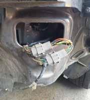
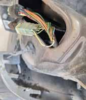

before unplugging the loom.
The loom was soaked with rainwater, had two broken wires and both connectors showed heavy corrosion.
Repaired the loom with two eight-pin Deutsch weatherproof connectors and rejoined all wires correctly. Problem fixed.
Diagnostic time for this job was two hours and repair time three hours.
Abdulkarem Fakhouri A1 AUTO REPAIRS MEADOW HEIGHTS, VIC


The automotive aftermarket is about more than parts – it’s about reliability, especially in rural areas where breakdowns can be critical.
In a major step, SPB Automotive is expanding westward in Queensland, bringing trusted ACDelco Premium batteries to three new locations: Roma, St George and Wandoan. New stockists include:
• Roma Tools & Industrial Supplies – 18-24 Hawthorne Street, Roma, Qld, 4455.
• Sunshine Mitre 10, St George – 147-161 Grey Street, St George, Qld 4487.
• Bolt Tyre and Mechanical – 7 Zupp Road, Wandoan, Qld, 4419.
For rural communities, having local access to quality parts means less downtime waiting for coastal freight. This expansion strengthens local businesses and keeps vital agricultural and industrial hubs moving.
ACDelco Premium batteries are built for harsh Western Queensland conditions. Their robust, maintenance-free design includes corrosion-resistant terminals, strong vibration-resistant cases and advanced high-density paste with full-frame grids for superior cranking power and longer life – even in extreme heat.
Beyond quality, peace of mind is part of the package. ACDelco batteries come with a national warranty, offering coverage Australiawide. Backed by SPB’s 25-plus years of technical expertise, local stockists and customers can count on reliable support just a phone call away.
‘Connecting the dots with these three new stockists is a major milestone,’ said SPB General Manager Damian Bartlett. ‘We’re not just selling batteries; we’re investing in the resilience of these communities.
‘This strategic move will strengthen the supply chain and give drivers and businesses across the region dependable access to toptier batteries and support.’
Geoff Mutton Business Resources
Modern vehicles are marketed as highly reliable and requiring less frequent maintenance. Debate continues as to how true this is in the real world.
Regardless, one thing is clear – customers are increasingly inclined to extend service intervals and delay maintenance.
The outcome is an evolving workshop landscape where the proportion of complicated diagnostic repairs – rather than routine servicing – continues to rise. This evolution puts pressure not only on our diagnostic skills but, crucially, our ability to recoup the time, tooling and expertise invested in diagnosing contemporary vehicle issues.
Diagnosis is a trained skill and one that should not be undervalued. Electricians and plumbers never work for free and neither should automotive technicians. Free diagnostic work devalues the industry and directly erodes your workshop’s profitability. More importantly, undervaluing diagnostics makes it harder to invest in ongoing staff training or to purchase vital tools such as scan tools, oscilloscopes or smoke machines.
The key is to create, train and stick to a clear diagnostic process that both your front office staff and technicians understand and buy into.
1. Define and communicate your diagnostic fee and inclusions
Set a diagnostic inspection rate that reflects your workshop’s skill and overheads. For example:
• Up to 60 minutes of investigation by a qualified technician.
• Includes: Road test, visual inspection, basic testing, scan-tool interrogation, live and freeze-frame data analysis, research in professional databases and a detailed report.

• Investment: $130+GST (adjust for your market and expertise).
The critical element is to explain very clearly to the customer:
• What the fee covers (diagnosis only, not repair).
• The value of your process (your specialised tools, knowledge and reporting).
• What they will get at the end (an inspection report).
This helps manage expectations and prevents misunderstandings such as a customer assuming $130 buys a complete repair.
2. Handling walk-ins and have-aquick-look requests
Local loyalty is valuable but so is your time. The balance is to show initial goodwill –for example, by spending a few minutes clarifying the problem and performing a quick visual check.
If further investigation is needed, clearly explain the next step is a formal diagnostic assessment at your set rate. If the customer isn’t willing to pay, refrain from further involvement. This approach wins trust, filters out tyre-kickers and maintains workshop integrity.
3. Perform the inspection within the agreed terms
When a customer finances an hour, stay disciplined: don’t exceed the agreed time unless further approval is given.
The focus should be on progressing the job – clarifying the nature and probable location of the fault – not delivering a guaranteed solution in 60 minutes. Use professional tools and procedures to document findings and communicate these in layman-friendly language.
4. Leverage technology and external support
Modern diagnostic work demands ongoing research and engagement with professional support resources. Incorporate advanced diagnostic platforms (e.g. scan tools, oscilloscopes) but also consider external resources.
The inclusion of TaT’s Tech Tina artificial intelligence (AI) on the TaT website is transforming workflow for many TaT

members. Instant access to real-world case studies, step-by-step diagnostic checklists and reference material is now at your fingertips. This not only increases diagnostic accuracy but helps justify your diagnostic charges by showing the customer your depth of resource and professionalism.
5. Clear and transparent reporting At the conclusion of the diagnostic inspection, deliver a clear outcome:
• Provide a fixed quotation to repair the problem, if identified.
• Advise the need for additional diagnostic time, seeking explicit further approval.
• Recommend a specialist or another workshop if the job is outside your equipment or skillset.
Regardless of the outcome, ensure the customer pays for the diagnostic work performed.
6. Diagnostics during scheduled services
It’s common for customers to mention a specific fault during a routine service visit. To protect service profitability, never allow diagnostics to eat into flat-rate servicing time. Honour any initial goodwill by spending a few minutes investigating but if further work is needed, revert to your standard diagnostic process and charge accordingly. Again, communicate this clearly and obtain agreement before proceeding.
Diagnostics is the most intellectually demanding, tool-intensive and high-stakes work most workshops perform. It therefore deserves at least as much compensation as any other technical labour, if not more.
Approaching it systematically, communicating value openly and charging accordingly will strengthen your reputation, increase profitability and deliver more satisfying outcomes for both customers and staff.
The Australian market is flooded with flimsy, overpriced imported rollcabs.
BAC Systems, however, is already producing what could be considered one of the world’s best toolboxes right here in Australia using Australian steels and local workers.
It can sometimes be easy to tell when you’re buying an imported rollcab – they can either have undersized castors, be made from steel less than a millimetre thick or be classified by their width in inches and the number of drawers.
Of course, once the length has been converted to metric and even knowing the number of drawers, you can still be left with many questions about how much can actually be stored inside the trolley.
BAC Systems aims to help customers store
their tools effectively by providing clear information on usable storage options. With its patented BAC Modular Drawer System, BAC can help you select your dimensions from its extensive range, choosing drawer heights to suit your tools and determining the appropriate number of drawers.
Additionally, BAC offers a variety of toolbars for drawers, including tool clips, posts and dividers – all designed to help organise and store tools neatly.
Australians expect longevity and value for money. A BAC Systems rollcab is built with large roller bearings instead of telescopic runners. These bearings are engineered to not wear down for many decades, despite the tool weights in the drawers, meaning the drawers always run smoothly and reliably.
BAC’s Single Drawer Lock, a thumb-operated
latch on the front of the drawer, is designed to be the most reliable method for preventing a cascade-tip on the trolley while still giving the user the freedom to choose to open more than one drawer at a time. It’s prominent and reliable.
Rollcabs manufactured by BAC Systems, more commonly referred to as BAC Trolleys, are built to be reliable and user-friendly. They are built to take hundreds of kilograms of tools and give the user ready access to these instantly.
They are also built to be safe but not to hinder the user with nanny-like one-drawer-at-a-time features.
BAC Trolleys are built in Australia to deliver fantastic value for money compared to some big-name toolboxes. BAC Trolleys, most importantly, are modular and can be set up to suit your inventory of tools and how you wish to access them
• To find out more about BAC Systems’ range of trolleys, rollcabs, toolboxes and mobile storage solutions for workshops, contact the BAC Technical Sales Team on 02 9832 2777, email bacsales@bacsystems.com.au or go to bacsystems.com.au
One of the most important yet often overlooked stages of installing a new turbocharger is pre-lubing.
Omitting this step can lead to premature wear and tear or, in the most extreme cases, turbo failure on start-up.
Oil is a turbo’s best friend
Turbochargers are highly complex devices, subject to remarkably high rotational speeds and operating to incredibly precise clearances. It takes just a few seconds for a lack of oil to cause catastrophic damage.
The thin, golden lining
The tolerances of these high-precision parts are marginal and the revolution speeds can exceed 100,000 revolutions per minute. The
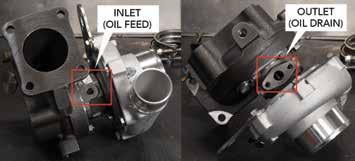
central axis, movable vanes and turbine wheel are centred using a thin film of compressed engine oil. That thin film is the only thing protecting the moving components of a turbocharger from friction.
When the turbo is in storage for extended periods of time, this oil succumbs to gravity, often leaving the oil passages dry.
Now imagine starting a turbo without that crucial thin lubricating film in place. Most turbos will start spinning at extremely high RPM very quickly and before the engine oil makes its way to the bearings, the shaft and other friction points, meaning the damage has been done.
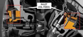
The location of the oil feed (inlet) port varies from turbo to turbo but usually, the inlet will be the smaller, threaded port at the top of the turbo, while the oil drain (outlet) port will be the larger, usually unthreaded port at the bottom of the turbo.
Adding a Pre-Lube ensures proper lubrication of the turbo bearings and shaft on the start-up.
Pre-lubing is a short and easy process that ensures a turbo’s longevity, performance and efficiency. Using a good quality, fully synthetic pre-lube such as JLM Turbo PreLube is highly recommended.
Pre-lubing a turbo before start-up
1. Dispense the tube of pre-lube to the turbo oil-inlet hole.
2. Manually turn the compressor wheel to distribute the pre-lube around the bearings.
3. Pre-fill and fit the oil-feed line.
4. Fit the inlet and outlet air hoses to the compressor housing, making sure the connection is air-tight.

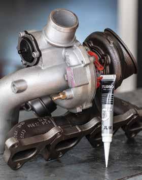
JLM’s Turbo Pre-Lube has been specifically formulated to protect the inner moving parts of a new turbocharger.
5. Without starting the engine (i.e. disconnect fuel or ignition), crank the engine for 10-15 seconds to prime the oil feed to the turbo.
6. Reconnect fuel/ignition and start the engine.
7. Run the engine at idle for three to four minutes to check for any oil, gas or air leakage.
Remember, turbochargers are high-tech, complex and precisionbuilt mechanical devices that rely on lubrication to function. Ensuring adequate lubrication right from the start will prevent expensive repairs or premature wear and tear.
GCG Turbochargers is one of Australia’s most respected turbo distributors. Founded in 1979, the company now holds more than 4000 turbos from all major manufacturers in stock, offering sameday dispatch and prompt, nationwide delivery from its Sydney and Brisbane warehouses.
• To find out more, go to gcg.com.au

The automatictransmission gear selector on this 2015 Nissan X-Trail (T32) was sometimes not coming out of park.
Inspected the vehicle and confirmed it wouldn’t come out of park approximately half of the time.
Confirmed the brake switch was working correctly but
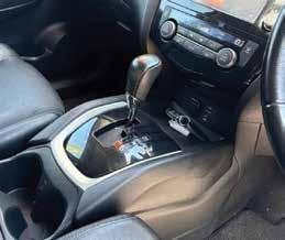

discovered that shaking the T-bar or hitting the centre console would allow the gear selector to come out of park.
Gained authority from the customer to remove the centre console and found the parkposition microswitch on the selector was intermittently not registering the park position. Replacing this assembly solved the issue.
The microswitch assembly (part number 34950-3RV1B) is sold separately from the whole shifter assembly. The repair requires depinning the connector to install the new switch assembly.
Diagnostic time for this job was 90 minutes and repair time one hour.
Brendan Sorensen
Steve Sorensen Mechanical BROWNS PLAINS, QLD

OK, so the title of this post is clickbait. But it is a valid question.
After posting a positive experience using TaT’s artificial-intelligence (AI) feature, Tech Tina, on the Garage Network page, an interesting discussion followed – could it lead down a diagnostic rabbit hole? Proponents of that position are absolutely right in stating that an inexperienced tech could spend lots of time and potentially customer’s money not fixing a fault.

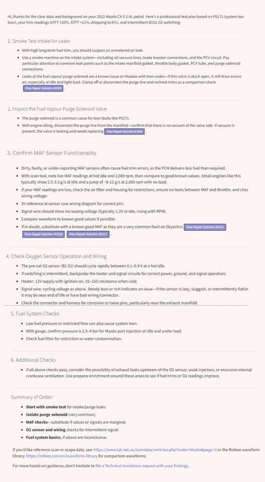
But here’s the catch; it can also save a lot of time. So let’s look at this case study of 2012 Mazda CX-5 2.0-litre petrol that presented with a P0171 fault code.
After downloading the fault code and carrying out a quick analysis of fuel-trim data, the long-term fuel trim showed at plus 20 per cent and short-term at plus 11 per cent at idle. At 2000 RPM, the short-term trim reduced to approximately plus six per cent and the long trim continued to approximately plus 17 per cent (pic 1).
At this stage we asked Tech Tina the following: ‘I have a 2012 Mazda CX-5 with a 2.0-litre petrol engine. The vehicle has a P0171 code and the long-term trim is at 20 per cent. The short-term trim is at 11 per cent idle. At 2000RPM short-term drops slightly to six per cent. We have noted that the bank one (B1) sensor one (S1) oxygen (O2) sensor stops switching properly intermittently. What would your test plan be?’
Tina’s response – see pic 2.
As an experienced tech reading through Tina’s response, it was easy to see some of the amalgamated specs did not apply to this vehicle, so my next question reiterated that this car had a wideband B1 S1 O2 sensor. Her response – see pic 3.
I then asked if it is possible to do a fuel-trim reset. Her response – see pic 4.
What I liked about using Tech Tina is you could form a test plan that could be given to a customer very quickly. Writing a report and request for diagnostic time was also much quicker.
I also liked that the system provided links to known good data on TaT’s website and previous case studies involving common issues for this vehicle regarding this fault code. This saves so much time when investigating values. I also liked that it gave some rule-of-thumb data for mass air flow (MAF) specs and, when prompted, wide-band O2 sensors.
In this instance, the fault with our vehicle was with the MAF sensor and we were able to follow the test plan to come to this conclusion without trying any other fixes first, mainly because our MAF values were jumping around at idle between 1.4 grams per second (g/s) and 1.8 g/s.
What was interesting was the known good data on TaT showed variations between vehicles but, generally speaking, in a very different range to what we had. Luckily, a Mazda 3 in the workshop was able to provide a known good MAF and the fuel trims corrected instantly, which meant selling the fix confidently.
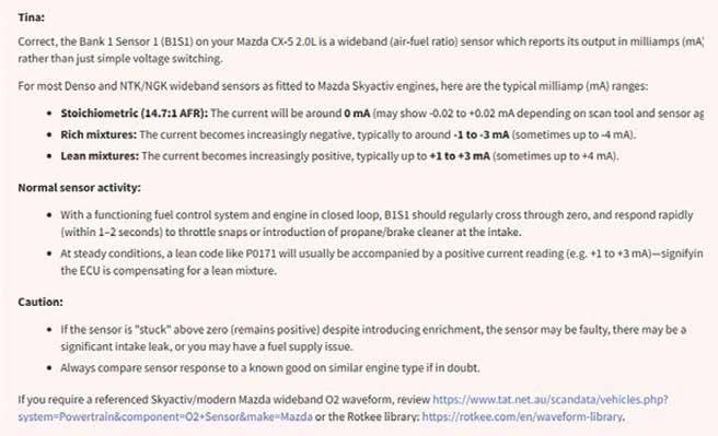
It leads me to thinking about how an inexperienced tech would go in this situation. There are definitely pitfalls if you don’t ask the right questions or critically think about what is being presented to you but there is a much bigger picture we need to consider and that is recruiting and retaining young people into our industry.
It is clear to me as I watch my kids go through high school they are learning differently. They are using the tools at their disposal; they are learning to think critically about what is presented to them.
As a business owner, I definitely see my role changing to accommodate the next generation that comes through. I need to lead them to the information and check their thought process more and be less direct in my responses to them.
I need to ask more about where they are getting their information from and to consider its accuracy. I need to guide them through a process, help them see where the logic is not right, help them ask the right questions and give them the benefit of my experience. Most importantly, I need to adapt to the tools available to us now and embrace the change.
Jeremy Stone – TaT member, owner/operator of Car Servicing and You

In automotive a/c, Alcius is a trusted choice for workshops and trade customers seeking reliable parts that meet both aftermarket and OEM quality standards.
With a reputation built on technical expertise and a comprehensive product range, Alcius has become a go-to brand across the industry.
Alcius a/c products are known for precision of engineering and the rigorous technical testing applied to each component. The design process starts with a thorough understanding of vehicle operating environments. Alcius engineers recognise that modern vehicles require efficiency, durability and seamless integration, so every product is designed to meet or surpass OEM standards.
A key element of the Alcius approach is comprehensive design and end-to-end product testing. Products undergo accelerated life-cycle simulations, vibration analysis and extreme thermal stress testing to mimic real-world conditions. Specifically, Alcius compressors are manufactured with precise CNC machining and specialised treatments that boost strength and durability. Fully automated assembly involves in-process quality audits at each stage and includes 100 per cent leak and performance testing on completion. Alcius condensers are designed to OE standards using computeraided design (CAD) design and Ansys heat-simulation comparisons. Controlled-atmosphere brazing (CAB) with precise temperature control and automated fin stamping and header forming, along with wind tunnel and final product bench testing, ensures the highest quality production. Helium testing and pressure-drop testing is performed on 100 per cent of manufactured items.
Alcius’ commitment to technical compatibility ensures installers can confidently fit the brand’s components, knowing they will perform as intended from day one. Quality assurance is integrated at every stage, from raw material sourcing to final product inspection and packaging. Each unit undergoes strict checks, supported by traceability and compliance systems to maintain consistent standards.
This careful process provides technicians and end-users with peace of mind that Alcius products will deliver superior performance even in the most challenging conditions.
Ultimately, Alcius is more than just a parts supplier – it’s a technical partner for workshops and installers. By investing in advanced design and testing, Alcius makes sure every product balances innovation, reliability and practicality. In an industry where downtime can be costly, that commitment matters.

Through relentless testing, innovative design and a commitment to quality, Alcius a/c products redefine what it means to keep vehicles cool and customers satisfied.
• To find out more, go to alcius.com.au
