A few things about this book before you start reading Quantities, units, numbers, and mathematical signs are placed within brackets. The somewhat unusual manner is meant to make it easier for the reader to recognize quantities and numbers, and for no other reasons.
Example: ……. the reference arrow for (U) has a (+) and a (-) side …… ……. if the resistance is (1,5Ω) and the ………...
Also note that decimal commas are used instead of decimal points.
Example: 10,15 instead of 10.15
BRIEF ELECTRIC HISTORY
The field of electrical engineering is already large but still increasing in both scope and importance. This has not always been the case, on the contrary, it has taken humanity a long time to develop today's level of knowledge. Several persons and discoveries have contributed. Some of the more significant may start the orientation of the subject.
600 BC
Thales from Miliots, about 625 - 545 BC, one of the seven wise in Greece, draw attention to the phenomenon of frictional electricity associated with amber, which in Greek is called electron.
250 BC
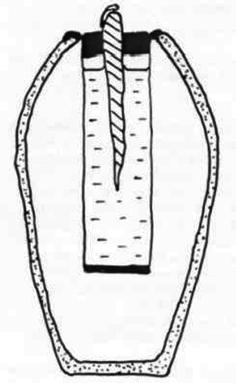
The Baghdad battery, a possible prehistoric battery dated to 250 BC. It was unearthed at Khujut Rabula on the outskirts of Baghdad. The find has puzzled researchers and it has not really been possible to understand what the “battery” may have been used for, or how they got the idea
16th-17th century
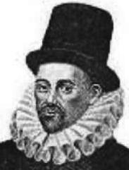
William Gilbert, 1544 – 1603, English physician and physicist known for magnetic experiments and the theory that the Earth is a huge magnet that clarifies the behavior of compass needles. Gilbert also introduced the word electrics.
18th-19th century:
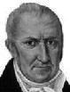
Alessandro Volta, 1745 – 1827, Italian physicist who invented the battery and got the unit of voltage (V) named after him. With a continuous power source, it became possible to investigate the effects of current.
Hans Christian Ørsted, 1777 – 1851, Danish chemist and physicist discovered in 1820 that a live conductor is surrounded by a magnetic field, and thus gave us the basis of electromagnetism.
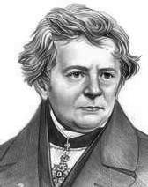
George Simon Ohm, 1789 – 1854, German scientist honored by having the unit of resistance (ohm, Ω) named after him. Ohm developed the idea that it is the voltage that causes current in an electrical circuit and published in 1827 in Die galvanische Kette, matehematish bearbeit the basis of electrical circuit theory: Ohm's law.
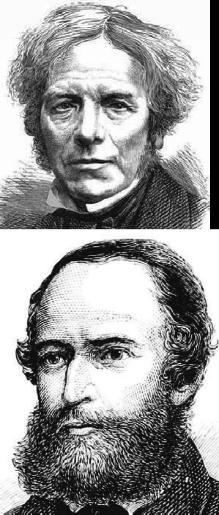
Michael Faraday, 1791 – 1867, English bookbinder who read the scientific books he worked with in sly This led to the Royal Institution where he was appointed professor in 1833. During this time, he discovered electromagnetic induction, the basic of generators, transformers, electric motors and more.
Gustav Kirchhoff, 1824 – 1887, German physicist who developed rules for calculating currents and voltages in electrical circuits, known as Kirchhoff’s current and voltage laws.
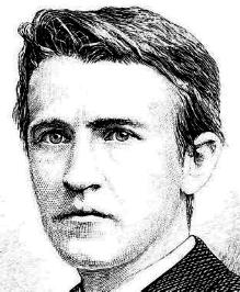
Thomas Alva Edison, 1847 – 1931, self-taught American inventor who invented of the first useful microphone and the phonograph for recording and playback of sound. He was also the first to design a useful light bulb and to build a power grid.
Jonas Wenström, 1855 – 1893, Swedish inventor designed and received a patent for the three-phase system, which was first used in Sweden in 1893. Wenström’s inventions became the basis for the large company ASEA, later ABB.
20th century
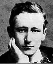
Guglielmo Marconi, 1874 – 1937, Italian researcher succeeds in wireless telegraphic transmissions from Europe to USA. In 1909 he receives the Nobel Prize in Physics for his contributions to wireless radio transmission.
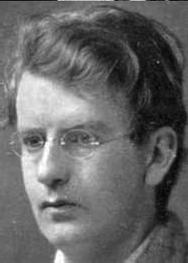
John Baird, 1888 – 1946, Scottish electro engineer who developed Paul Nipkow's method to convert an image into an electric signal and in 1924 managed to transmit a TV image and thereby start the development of television.
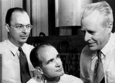
William Shochley, John Bardeen, and Walter Brattain, three American researchers published in 1948 their successful experiments with the transistor. For their efforts, the research team was awarded the Nobel Prize in Physics in 1956.
21th century
The reader of this book.
1 THE MULTIMETER
This section informs about multimeters. It is a benefit to have multimeters at hand when reading the section. When you are done, you should be able to identify and set the different functions and read the different scales.
ANALOG & DIGITAL
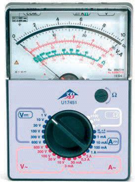
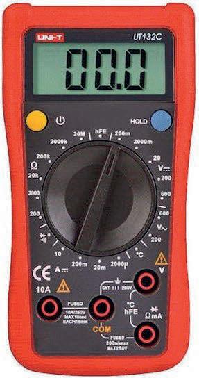
There are two different types of multimeters, analogue and digital. Both types have measurement functions for resistance, voltage and current. Some models have even more measurement functions such as frequency and capacitance. Analogue multimeters display the measurement result using a pointer that moves across a scale, while digital multimeters shows the measurement values by digits.
CONNECTION & FUNCTION SELECTION
The photos show examples of typical analogue and digital multimeters. The different measurement functions and ranges are set with a function switch. The instruments above have “turnaround-switches”, but there are also multimeters with push buttons.
Analog
Digital
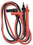
Probes
Test-yourself 1
THE MULTIMETER
Test-yourself by reading the summaries that end each section. If you recognize the concepts and descriptions, it is a satisfactory proof of your knowledge. In several sections the summary is followed by calculation exercises. Remember to make drawings when prompted, it help us to think electricity correctly.
SUMMARY
1. Multimeters can be divided into two groups, analogue and digital.
2. Analog instruments display the measurement result with a pointer that moves across a scale.
3. Digital instruments display the measurement result with digits.
4. Multimeters combine at least three different measurement functions in the same instrument, voltage-, current- and resistance measurement. Many multimeters have more functions for measurement, e.g. frequency and capacitance
5. Switching between measurement functions and measuring ranges is done with a function switch.
6. It is important that the correct measurement function and the correct measuring range are set correctly before each measurement to ensure the instrument is not damaged
7. If you are unsure which measuring range to use, always start with the highest measuring range.
2
RESISTANCE & MEASUREMENT
This section informs about the concept of resistance associated with some common resistor types and how the multimeter is used for resistance measurement.
When you are done, you should be able to measure resistors, read the colour code, account for the default values in the E6 and E12 series, the function of potentiometers and determine their settings by resistance measurement.
RESISTORS
Resistors are a quite common component in electrical circuits. The propertyis called resistance and in electrical circuits it is an obstacle to current.
The quantity is denoted by (R) and measured in the unit ohm, which is denoted by the Greek letter omega, (Ω).
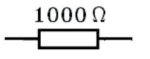
In electrical drawings, the resistor is indicated by a symbol and its resistance value with a number followed by a ( Ω), e.g. (1000Ω).
Resistor symbol
MARKING OF RESISTORS
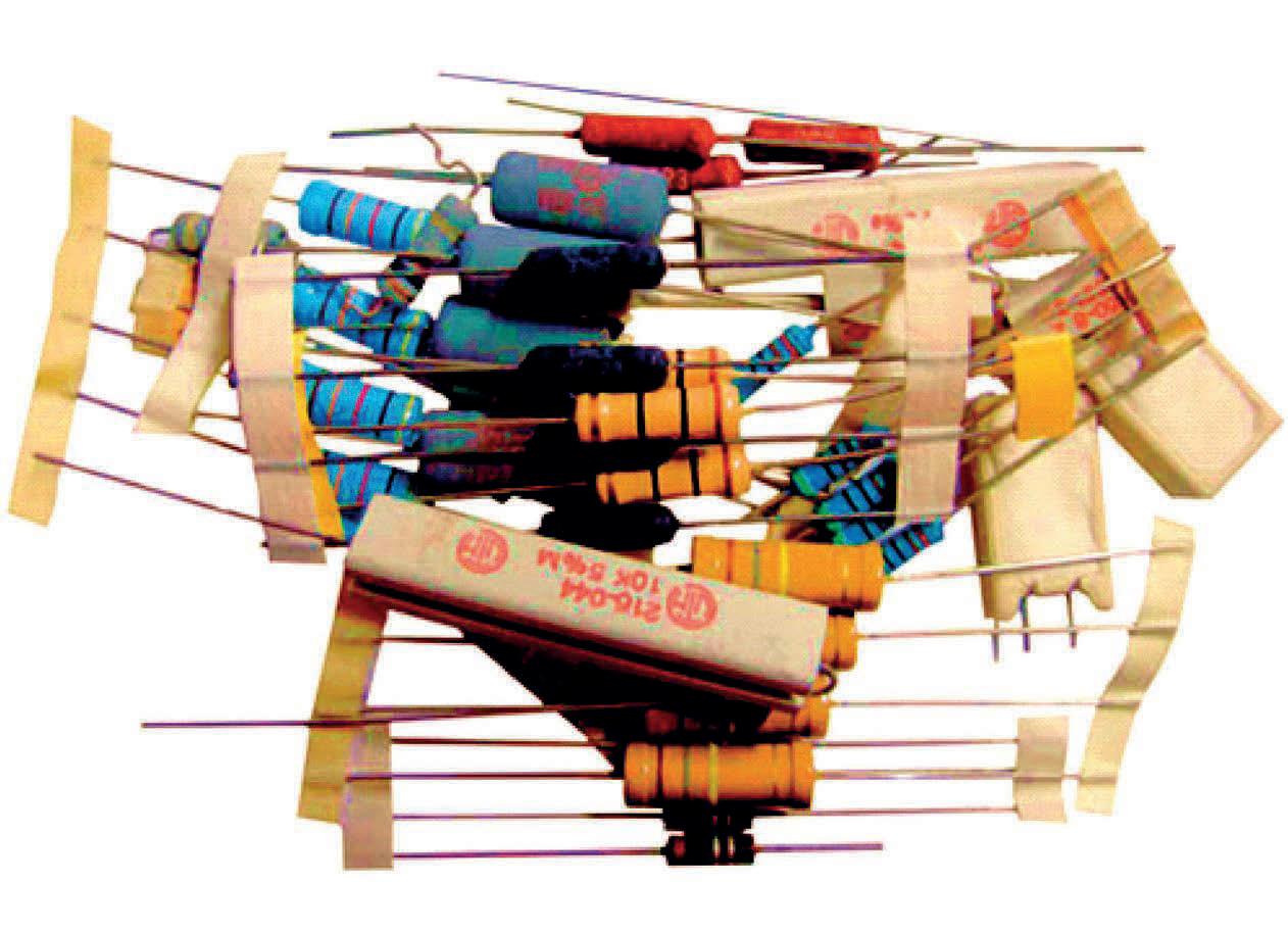
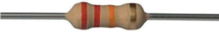
Resistors look quite different. The value of larger resistors is often showed with text while small resistors have a specific colour band code.
COLOUR CODES
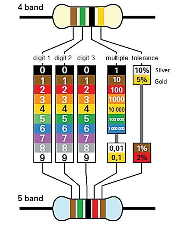
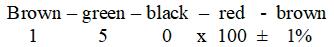
The colour code consists of either four or five colour bands. The placement and the colour decide the value of the resistor. In a four-band code is the first band the most significant digit. The second band the next most significant digit. The third colour band indicate a multiple number by which the first two numbers shall be multiplied. The fourth colour band show the tolerance.
TOLERANCE
Tolerance means a deviation from the nominal value indicated on the resistor. A resistance with a value of 1000Ω and 10% tolerance might have a resistance value between (1000Ω + 100Ω = 1100Ω) and (1000Ω -100Ω = 900Ω) because 10% of 1000 is 100.
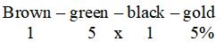
Example: The resistor below has four colour bands, from left to right (red = 2), (red = 2), (orange = x 1000) and (gold = 5 %)
The resistor has a nominal value of (22000Ω ± 22000 x 5%) or expressed in kilo-ohm: (22kΩ ± 1,1kΩ).
Test-yourself 2
RESISTANCE & RESISTANCE MEASUREMENT
SUMMARY
1. Resistors are a very common in electrical circuits.
2. The unit of resistance is ohm and is denoted (Ω).
3. The values and tolerance of resistors are indicated by a colour code or text.
4. The first three bands of the color code indicate the resistance value, while the fourth band shows the tolerance.
5. The tolerance indicates in (%) how much the resistance value can deviate from the nominal value.
6. Resistors are manufactured with different values in so called E-series in which the values are repeated ten times larger in each subsequent decade.
7. Potentiometers are resistors with three connections. Two side sockets between which there is a fixed resistance value and a centre outlet with a sliding connector.
8. Between the centre socket of the potentiometer and the two side sockets, the resistance values are adjustable.
9. Ω-scales on analogue multimeters are not linear, i.e. the value between the scale divisions is not the same across the entire scale.
TEST-YOURSELF
1. Which letter is used to denote resistance?
2. How is the unit of resistance denoted?
3. Which resistor and tolerance value corresponds to the following colour bands:
This section describes the concept of voltage, ordinary batteries and how to measure DC-voltage.
When you are done, you should be able to set a multimeter for DC measurement and measure the voltage of series- and parallel connected batteries.
VOLTAGE
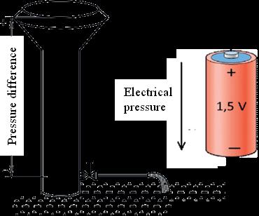
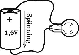
Voltage can be said to be an electrical pressure difference that makes current to flow in electrical circuits, much like the pressure difference in water towers causes a flow of water in water pipes.
The electrical voltage has the designation (U) and is measured in volt (V). As a result of the unit (V), multimeters set for voltage measurement are called voltmeters.
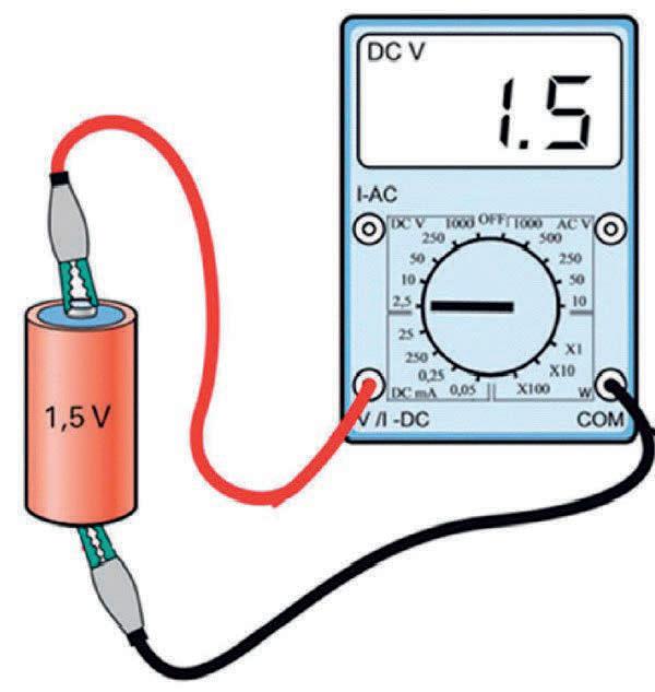
See below how the electrical pressure difference, the voltage between a battery's plus and minus pole is measured with a multimeter.
Remember!
Voltage is always measured between two points.
5 POWER SUPPLY
This section informs about electronically stabilized power supplies, the controls they usually have and how they are used. When you are done, you should be able to use stabilized power supplies.
GENERALLY
Stabilized power supplies convert the 230V AC-voltage from the mains to DC-voltage. A typical stabilized power supply delivers an adjustable DC-voltage between 0 and 40V that remains stable even if the mains voltage or the output current changes.
It is common for a voltage unit to have two or more independent output voltages with separate connection terminals and setting possibilities. The connection terminals are usually marked with (+) and (-), or with red colour for the positive and black or blue for the negative terminal.
The picture shows a typical stabilized voltage unit with digital display for output voltage and / or output current.
Symbols for voltage sources
Battery Variable General symbol voltage symbol source
In electrical drawings, voltage sources are usually represented with one of the three symbols. On the right we have the general symbol for DC-sources, and on the left we recognize the battery symbol. If the battery or the general symbol is supplemented with an arrow, it means a voltage source with adjustable output voltage.
Unfortunately, it has not been very successful to introduce a common standard for electrical drawings. Sometimes the battery symbol is used for voltage sources other than batteries.
6
CURRENT & MEASUREMENT
This section describes the concept of current and how current is measured by a multimeter. When you are done, you should be able to set and connect a multimeter for current measurement
Current
Current is electrical charges in motion and cannot, unlike resistance and voltage, exist alone. Resistance exists and can be measured in resistors, in wires and in various materials. Similarly, voltage can exist in batteries and power supply units. For current to exist, there must be a voltage source with an electrical pressure difference, such as a battery, and a closed circuit between the plus and minus terminals in which the current can pass
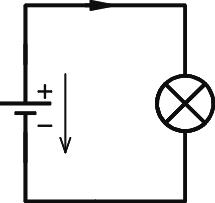
The circuit below shows a closed circuit with a lamp attached to a battery and how it looks like in an electrical drawing.
The same circuit when the filament of the lamp has broken and opened the circuit between the plus and minus poles (terminals) of the battery.
In an open circuit there is no current
If the lamp is replaced with a new with unbroken filament the current starts to flow immediately in the whole circuit.
AMPERAGE
Previous was mentioned that current is electric charges in motion. In a wire are the number of charges passing through a cross section of the wire per second a measure of the current.
Current is denoted with (I) and the unit in which the current is measured, ampere, is denoted (A). A multimeter used for current measurement is therefore often called ampere-meter
7
OHM’S LAW
This section describes Ohm's law, the basis of electrical circuit thinking. When you are done, you should be able to use Ohm's law in calculations of electric circuits and to predict measurement results.
Georg Simon Ohm was a German physicist who lived from 1787 to 1854. His discovery of the fundamental relationship between voltage, current and resistance was published 1827.
REFERENCE ARROWS & DESIGNATIONS
In the previous sections, you have been familiarized with voltage, current and resistance. The mathematical relationship between these three quantities in Ohm's law will soon be introduced.
For Ohm's law to get a meaning, we must relate the mathematical formula to the actual circuit with a drawing, reference arrows and designations to make the relations visible.
The circuit in our discussion consists of a voltage source and a resistance connected to the plus and minus poles (terminals).
We know that the battery symbol means voltage and that there is a current flow from the plus pole of the battery, through the resistance, back to the minus pole of the battery. It is not so difficult when the circuit is simple, but when calculating and analyzing more complicated circuits it is. Electrical thinking needs support of reference arrows and quantity-designations.
The current-arrow marks the current (I) with the direction from the plusto the minus pole of the voltage source. The voltage drop arrow marks the voltage (U) across the resistance (R). Note that the reference arrow for (U) has a (+) and a (-) side and that the voltage falls from a higher to a lower value in the same direction as the current flow.
OHM’S LAW
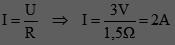
With the designations in the image, Ohm’s law is mathematically written as follows:
In words:
I = current in A (ampere)
U = voltage in V (volt)
R = resistance in Ω (ohm)
The amount of current through a resistance is equal to the value of the voltage drop across the resistance, divided by the value of the resistance.
Example: Calculate the value of the current through the resistor if the resistance is (1,5Ω) and the voltage drop across the resistance is (3V).
UNITS
For the current (I) to be obtained in the base unit (A) ampere, the voltage (U) must be specified in (V) volt and the resistance in ( Ω) ohm. Sometimes one or more of the three quantities are known in smaller or bigger units, for example, (mA) milliampere or (kV) kilovolt. For beginners, it is wise to convert to base units before they are inserted into Ohm's law. The following compilation show the sizes between the base units and the upper- and subunits that are most common.
CURRENT (I)
Base unit is 1A (ampere)
1mA(milliampere) is one thousandth of 1A
1A = 1000mA
1mA = 0,001A
1μA, (microampere) is one millionth of 1A
1A = 1 000 000μA
1µA = 0, 000 001A
VOLTAGE (U)
Base unit is 1V (volt)
1kV, (kilovolt) is one thousand volts
1kV = 1000V
1V = 0,001kV
1mV, (millivolt) is one thousandth of 1V
1V = 1000mV
1mV = 0,001V
1μV, (microvolt) is one millionth of 1V
1V= 1 000 000μV
1μV = 0, 000 001V
RESISTANCE (R)
Base unit is 1Ω (ohm)
1MΩ, (mega-ohm) is a one million ohm
1MΩ = 1 000 000Ω
1Ω = 0, 000 001MΩ
1kΩ (kilo-ohm) is one thousand ohm
1kΩ = 1 000 Ω
1Ω = 0, 001kΩ
1mΩ (milli-ohm) is one thousandth of 1Ω
1Ω = 1000mΩ
1mΩ = 0, 001 Ω
VOLTAGE CALCULATION
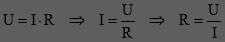
Since Ohm's law is a mathematical expression, the usual rules apply for the relationship between I, U and R. This means that one of the quantities can be calculated if the values of the other two are known.
Example: Through the resistor (6Ω) is a current flow of (3A). Which value has the voltage drop (U) across the resistance?
Reshape Ohm’s law and do the calculation as follows:
RESISTANCE CALCULATION
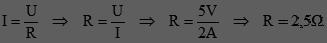
Similarly, resistance can be calculated if both the voltage drop and the current through the resistor are known.
Example: The voltage drop (5V) causes a current of (2A) through the resistor. What is the resistance value?
I / U - GRAPHS
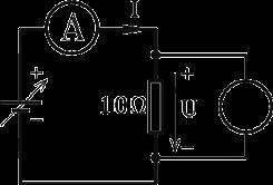
In electrical engineering, it is common to measure how the current through a component depends on the voltage across the component, as well as to represent the result in the form of an I / U-graph. Let's see how this is done in connection with the circuit below.
Circuit for measurement of an I/U-graph
The measurement is carried out by increasing the voltage in steps of ( 1V) from (0V) to ( 10V). For each voltage value is the current measured and noted. The table shows the readings and, to the right, how the results are inserted into the coordinate system.
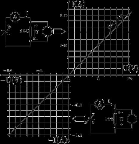
Note that the y-axis is designated with I (A) and the x-axis with U (V). This means that the graph shows how the current (I) depends on the voltage (U) and that the axes are divided into ampere and volt, respectively
To show that the graph applies to the resistor value (R = 10Ω), it is specified with a so-called parameter. With other resist or values, will the slope of the line be different.
Readings
Coordinate system with I/U graph
If the voltage source polarity is reversed, the current flows in the opposite direction through the resistor and the graph ends up in the third quadrant where the negative y-axis represents the reverse current direction (-I). Similar, the negative direction of the x-axis shows that the voltage (-U) across the resistor is reversed.
10 PARALLEL CIRCUITS
This section describes the concept of branch currents and Kirchhoff’s current law. When you are done, you should be able to calculate and measure branch currents.
Gustav Robert Kirchhoff was a German physicist who lived from 1824 to 1887. Kirchhoff did a variety of important work in physics but is most known for his laws in electrical circuit theory.
CURRENTS IN PARALLEL CIRCUITS
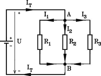
The picture shows a parallel circuit with three branches. Let us take a close look at this circuit.
The current (IT) flows from the plus pole of the voltage source to point (A) where it splits into the three branch currents (I1, I2 , and I3). At point (B) they are joined into a current with the same size as (IT), hence the common designation of the current from and back to the voltage source.
Remember! The current flow from the plus pole of a voltage source has always the same size as the current flow back to the negative pole of the voltage source.
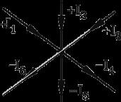
If we focus on the currents flowing to and from the branch points, (A and B), ignoring what has caused them or their size, we can make the same conclusion as Kirchhoff did:
The sum of currents flowing to and from a branch point is always zero.
Meaning that no current can stay in the branch point.
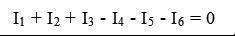
If the currents flowing to a branch point are counted as positive and the currents flowing from the branch point are counted as negative, it can be mathematically formulated as:
Example: To the branch point (A) is a current flow of (24mA). From the branch point flows the three currents (I1 = 8,2mA, I2 = 3mA) and (I3) which is unknown and must be calculated.
THE VOLTAGE ACROSS PARALLEL CIRCUITS
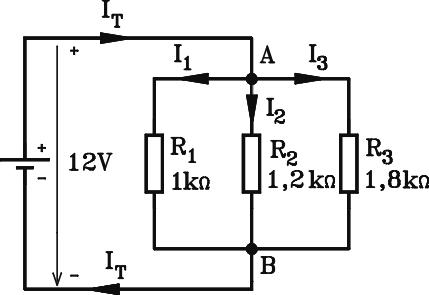
Study the circuit below. Between point A and B, which are directly connected to the plus and minus poles of the voltage source, there is a voltage of (12V). Since all three resistors (R1, R2 and R3) are connected between (A) and (B), there is (12V) across each of the resistors.
Remember: The voltage is the same across each branch in parallel circuits.
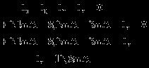
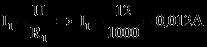
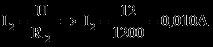
Example: Calculate the total current and the three branch currents using the specified voltage and resistor values.
Finally, the total current (IT) is calculated.
12
MIXED SERIES & PARALLEL CIRCUITS
This section shows how to calculate resistance, branch currents, and partial voltages in combined series and parallel circuits. When you are done, you should be able to calculate and measure total resistance, branch currents and partial voltages in mixed circuits.
MIXED CIRCUITS
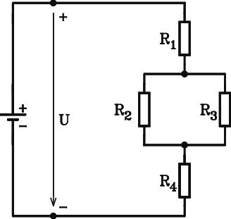
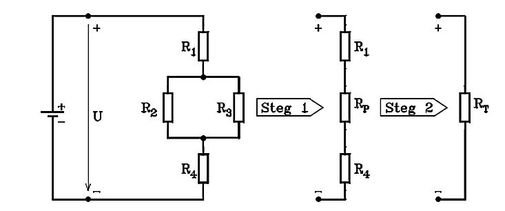
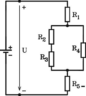
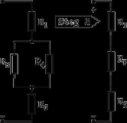
The circuit below can be described as a mixed series parallel circuit where the resistor (R1) is in series with the parallel combination (R2) and (R3) which in turn is in series with (R4).
The same methods that we have previously used for measuring and calculating resistance, currents and voltages also work for mixed circuits, but it is important to be systematic. By redrawing the circuit and carefully and consistently setting out reference arrows and designations, it is possible to calculate the replacement resistance, branch currents and partial voltages in the circuit above.
UPDATING
First an update of the formulas we will use:
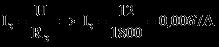
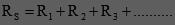
Replacement resistance (RS) for series circuits
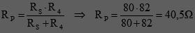
Replacement resistance (RP) for two parallel resistors
Ohm’s law in its three forms
Remember: It is an important support of electrical thinking to redraw the circuit with reference arrows and denotations before the calculation is carried out
CALCULATION OF THE TOTAL RESISTANCE
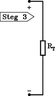
The total resistance (RT), seen from the (+) plus and (-) minus poles of the voltage source, can be calculated by gradually simplifying the circuit.
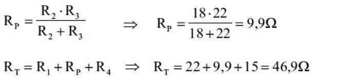
In the first step, the replacement resistance for the parallel combination (R2 // R3) is calculated. The circuit is then simplified to a series connection consisting of (R1, RP and R4). In the second step, the series connection is reduced to the total resistance (RT).
Example: Calculate the total resistance (RT) of the circuit if (R1 = 22Ω), (R2 = 18Ω), (R3 = 22Ω), and (R4 = 15Ω).
Example: Calculate the total resistance (RT) between (+) plus and (-) minus if (R1=100Ω, R2=47Ω, R3=33Ω, R4=82Ω, and R5=82Ω).
Observe the two series connected resistors, (R2) and (R3) in the parallel circuit!
13
KIRCHHOFF'S
VOLTAGE LAW
This section is about how Kirchhoff's voltage law can rationalize current and voltage calculations. When you have finished the section, you should be able to use Kirchhoff’s voltage law when calculating and measuring voltage.
KIRCHHOFF'S VOLTAGE LAW
Kirchhoff's voltage law can be formulated in different ways but still have the same meaning The starting point for our discussion is formulated as follows:
The sum of all voltages in a closed loop is equal to zero (0) when they are counted in the same direction.
There are two concepts that we need to sort out. What is a closed loop? And which direction are we talking about?
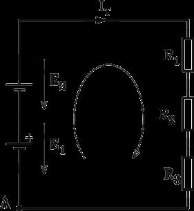
CIRCUIT WITH A SINGLE LOOP
Look at the circuit! It consists of a single loop with two voltage sources and three resistors. The voltage sources have the pole voltages (E1) and (E2), and across the resistors are the voltage drops ( U1), ( U2) and ( U3). The designation (E) has been introduced to clearly indicate the difference between the pole voltages of the voltage sources and the voltage drops across the resistors.
Let’s now make a note of the voltages in the loop with the beginning and ending at point (A), in the following order:
Count the voltage arrows pointing towards the loop direction as positive and those pointing in the same direction as negative. The result is:
Here’s an example with an electronic circuit which you can handle even if you don’t know anything about diodes and transistors.
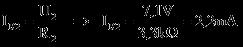
Example: The circuit represents a voltage stabilizer. During troubleshooting you shall determine the current (IR2) through the resistor (R2 = 3,3kΩ).
Use the loop:
Sum up the voltages:
Calculate the current:
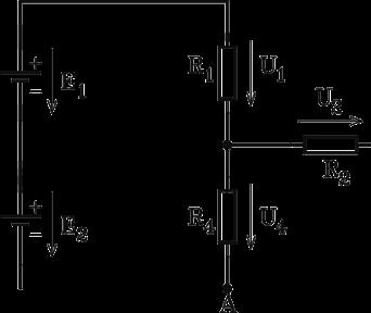
Example: Here is a circuit with three closed loops. Two of the loops have (E1), (E2) and (U1) in common, but which is the third loop?
Loop number 1:
Loop number 2:
Loop number 3:
Note that loop number 3 does not have a voltage source, but it is still possible to add together the voltage drops.
16
VOLTAGE SOURCES
This section deals with electromotive force, internal resistance, and load capacity of voltage sources. When you are done, you can calculate and measure the internal resistance, the electromotive force and the pole voltage of voltage sources.
HAVE YOU THOUGHT ABOUT THIS!
When you hear the words voltage source, you probably think of batteries and stabilized power supplies, but also microphones and TV-antennas are voltage sources with electromotive force and internal resistance.
Microphones convert sound to signal voltages
IDEAL VOLTAGE SOURCES
Antennas convert electromagnetic waves to signal voltages
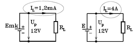
Ideally perfect voltage sources have an electromotive force (e.m.f) which provide a constant pole voltage (UP) no matter how much the load current (IL) varies, as illustrated below. The pole voltage (UP) remains constant (12V) even if the load current (IL) is (1,2mA) or (4A). Such voltage sources exist only in theory!
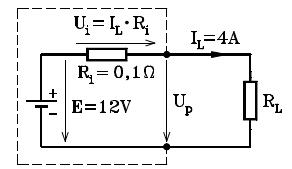
REAL VOLTAGE SOURCES
Real voltage sources behave as if there is an internal resistance (Ri) between the electromotive force (e.m.f) and the (+/-) poles. Please note that this is not a real resistor, but "something" that has the property of resistance
18 BASIC MAGNETIC CONCEPTS
This section describes basic magnetic concepts and some of the connections between magnetism and electricity. When you are done, you shall be able to describe magnetic phenomena, account for the screw and right-hand rule as well as for magnetic circuits.
PERMANENT MAGNETS
Some materials can be magnetized. Essentially, it is iron and some ferromagnetic materials such as cobalt, nickel and some alloys that have this characteristic. If a rod is made of such material, it is called a bar magnet
In the surroundings of such a magnet there is a magnetic field that exerts force action on iron objects. The phenomena can be demonstrated by slowly bringing two bar magnets closer together. Depending on how they are oriented they will either attract or repel each other.
The explanation is that the magnets have a north and a south pole. The force of a north and a south pole makes magnets attract each other. Two equal poles, two north or two south poles, on the other hand, have a repelling force and repel each other.
Different poles attract
Equal poles repel
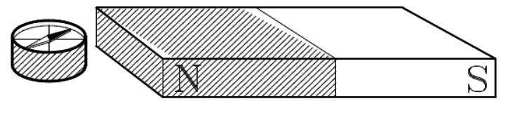
TEST MAGNETS
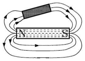
To investigate what are the north and south poles of a magnet, a small agile test magnet can be used, just like a compass. If the test magnet is placed near the magnet, the pointer turns the north side towards the south pole side of the examined magnet.
Test magnet in the surroundings of a bar magnet
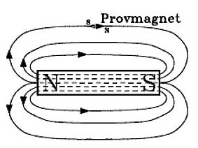
FLUX LINES & MAGNETIC FIELDS
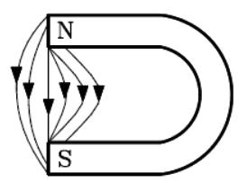
The magnetic field around magnets is illustrated with flux lines that each are a closed line. Outside the magnet, the flux lines have a direction from the north pole to the south pole. Inside the magnet the direction is reversed, from the south to the north pole.
The density between the flux lines is meant to correspond to the strength of the magnetic field but remember that the magnetic field is not only concentrated to the flux lines. The magnetic field exist also between the field lines.
Bending a bar magnet to the form of a horseshoe, concentrates the magnetic field lines to the gap between the north and south sides.
Iron objects placed in the magnetic field bend the flux lines, so they pass the objects instead of the surroundings.
MAGNETIC INFLUENCE & REMANENCE
Ferromagnetic material placed in a magnetic field becomes magnetic itself and has a residual magnetism if it is removed from the field after some time. This is called magnetic influence, while the remaining magnetism is called remanence.
Above the atomic level, this is explained as if magnetic materials are consisting of small elementary magnets with their own magnetic fields. In the non-magnetic state, they are in a complete disorder, causing the fields to counteract each other Under the influence of a stronger outer field, the elementary magnets get the same direction so that their fields co-operate outwards. The new direction is maintained even after the outer field is removed, in some materials more, in others less.
MAGNETIC FIELD SURVEY
The usual way to examine the magnetic fields around a magnet is to sprinkle iron flings on a sheet of paper placed on top of the magnet. The iron flings then form into an image of the magnetic field that is faulty. It looks like the magnetic field consists of field lines with spacing. The explanation is that each small iron fling has become a magnet and it is their interdependence that shapes the field line pattern.
ELECTROMAGNETISM
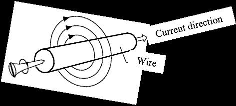
In the 1820s, the Danish physicist Hans Christian Ørsted discovered that there was a magnetic circle-shaped field surrounding wires conducting current.
This important field image can be described with the screw rule
It states that if a right-handed screw is turned so that it moves in the same direction as the current, the rotation gives the direction of the magnetic field.
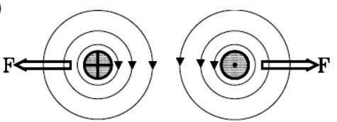
Ørstedt's research also revealed that between conducting wires, there are forces (F) which try to move the wires from the area where the flux lines direction coincides.
The wires move away from each other
Notice how the current direction in the wires is highlighted. The cross mark means that the current flows from the reader and the point, that the current flows towards the reader. Feel free to try the screw rule!
If the current flows in the same direction in both wires are the magnetic flux lines counteracting each other and it makes the wires to move towards each other.
The wires move towards each other
Ørstedt's discovery was the first step towards AC-technology and all it entailed of electric motors, generators, speakers, relays, transformers, and more ............
20 INDUCTION
This section is about how magnetic fields can be used able to generate an electromotive force (e.m.f.) that drives current. When you are done, you should be able to describe what is meant by induction and account for the quantities and units that belong to the concept.
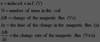
INDUCED E.M.F.
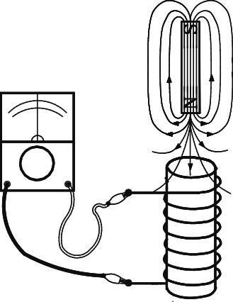
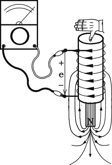
The image depicts a coil, connected for experimental purposes to a voltage meter with centered zero scale which can indicate whether the measured voltage is positive or negative. Near the coil there is also a permanent magnet in whose magnetic field the coil is located
E.M.F
The reading remains zero as long as the magnet doesn’t move, but if it does is an (e.m.f) induced (generated) in the coil.
The experiment suggests that changes of magnetic flow in the surroundings of a coil cause an (e.m.f) in the winding.
- DIRECTION
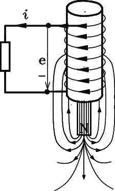
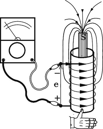
Suppose the permanent magnet falls through the coil. It causes the magnetic flux in the coil to grow until the magnet is halfway through the coil and decrease when it is on its way out of the coil. Observation of the voltmeter shows that the induced (e.m.f) changes both polarity and size.
If the coil is part of a closed circuit, the induced (e.m.f) causes a current like any voltage source.
The polarity of the induced voltage has always a direction that counteracts the cause of its emergence.
Let’s try the rule of the direction of the e.m.f in connection with the images below with the following reasoning:
To counteract the cause of its own emergence, the current from the e.m.f. must cause a magnetic flux in the opposite direction to that growing magnetic flux from the permanent magnet. When it decreases, the (e.m.f) must amplify the flux to maintained it at the same level, which explains the polarity change.
Growing flux
flux
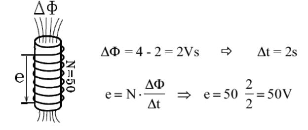
Devote some extra attention towards how the reference arrows change directions when the permanent magnet is on its way in and out of the coil. Test the right-hand-rule, to see if the specified directions of the current are correct! More accurate experiments show that the induced (e.m.f) in a coil is proportional to the number of turns and the flux change in the coil.
Example: How large is the induced voltage in a coil with 50 turns, if the magnetic flow enclosed by the coil changes from 2 to 4Vs in 2 seconds.
Declining
21
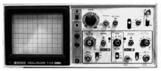
OSCILLOSCOPE
This section is an orientation about the function of oscilloscope, it’s settings and what can be measured with oscilloscopes. If you have access to an oscilloscope and can try it while reading, it is an advantage. When you are done, you should be able to identify and set the standard controls and use the oscilloscope to measure DC voltages (AC measurement comes in section 22).
GENERALLY
Oscilloscopes are fast voltmeters which in addition to DC- and AC-voltages, make it possible to measure frequency and time relations between AC-voltages. One of the advantages of oscilloscopes is that they show measurement results as X/Ygraphs, much like when drawing curves in coordinate systems with X- and Y- axes.
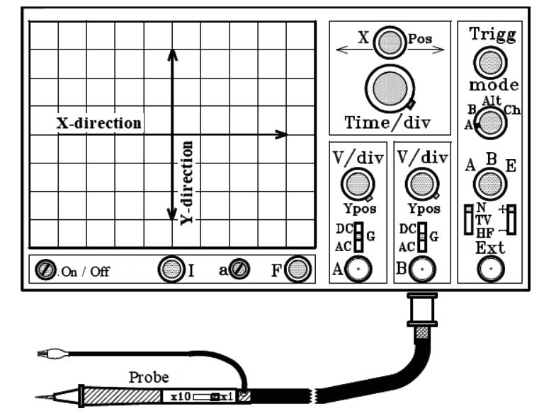
THE DRAWING FUNCTION
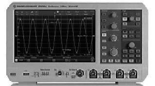
The image above depicts the front of an oscilloscope. A relatively large part is occupied by the screen where the examined voltages are displayed with one or more light points that sweep across the screen in X-direction at a selectable speed.
At low sweeping speed, you can observe the luminous point moving across the screen from left to right. With higher sweep speed, the light point becomes a solid line. The measured voltage deflects the light point in the Y-direction with a sensitivity chosen by the user.
22
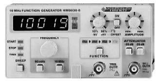
FUNCTION GENERATORS
This section is an introduction of function generators. The section also deals with basic measurement of AC-voltage with oscilloscopes.
When you are done, you should be able to set the level, the shape and frequency of the output signal and measure the characteristics of the set output signal with an oscilloscope.
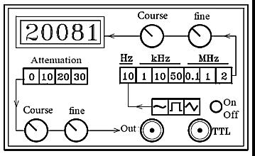
INITIAL INFORMATON
For measurement exercises in an AC-course, it requires an ACsource with variable output voltage, frequency, and curve shape. Function generators are such voltage sources.
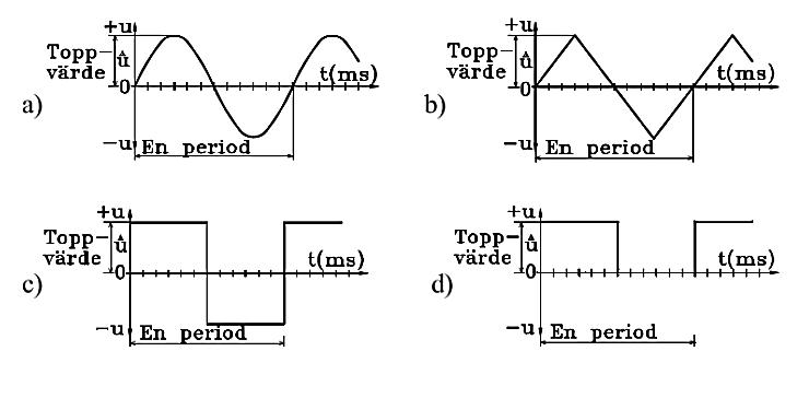
The concept AC-voltage refers usually to sinusoidal voltages because it is the most common form, but also other curve forms, such as triangular and square waves are AC-voltages. Function generators can generate all three curve forms and many more within a frequency range of tenths of Hertz (Hz) to several Megahertz (MHz)
PERIODIC AC VOLTAGE
AC-voltages repeated with the same size and curve form are said to be periodic. Here are examples of a) sinusoidal voltage, b) triangle formed voltage, and two sorts of square wave voltages, c) one passing the zero-line d) and one without passing the zero-line
24 AC VOLTAGE
This section introduces the basics of 1-phase AC. When you are done, you should be able to measure the characteristic values of AC voltages with multimeters and oscilloscopes, as well as relate the measurement to wave and vector graphs.
AC VOLTAGE SOURCES
The AC voltage in our wall outlets has an R.M.S. value of (230V) and a frequency of (50Hz). Please note that (230V) is a lethal voltage level! For electrical experiments and in service contexts, function generators with adjustment options of curve shapes, level, and frequency, are used.
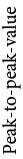
PROPERTIES OF AC VOLTAGE
Sinusoidal AC voltages are generally specified by the designations and names in the wave graph below.
Remember that the frequency (f) is an important quantity in alternating voltage and current contexts. Frequency is the number of periods during one second.
Note that the x-axis of the wave graph is divided into both degrees and time. The period (T) corresponds to (360°), half the period is (180°), etc....
Remember this because you need to convert time to degrees and vice versa when measuring and calculating AC circuits.
THE AC CIRCUIT
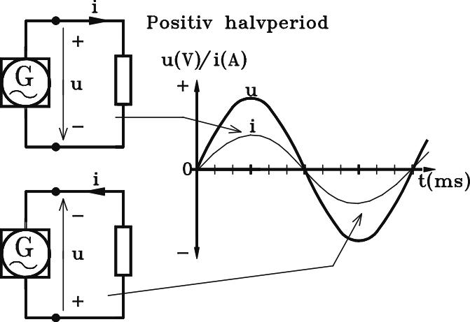
To understand what it means when AC voltage changes size and polarity we divide one period into one positive and one negative half-period.
Positive half-period
Negative half-period
During the positive half-period, the voltage grows from (0V) to a positive peak value and then subsides to (0V) again. When the negative half-period starts, the voltage changes polarity and decreases towards a negative peak value and then again towards (0V) before the process is repeated.
Note how the reference arrows show that the polarity is reversed during the positive and negative half-period and how the currentdirection changes Remember that the current always has a direction from the plus pole of the voltage source to its minus pole and thus changes direction twice in each whole period.
REFERENCE ARROWS IN AC CIRCUITS
Is it possible to use reference arrows for voltage drop and current in AC circuits when both voltage and current change directions all the time?
Yes, it works, but in AC circuits the reference arrows can only show the polarity of the voltage and the direction of the current if you limit yourself to half periods or instant values. As support forelectricalthinkingthe reference arrows are still valuable for displaying voltages and currents in AC circuits.
R.M.S. – ROOT-MEAN-SQUARED VALUE
When calculating and measuring in AC circuits, it is important to understand the meaning of R.M.S. values and to be able to convert peak values to R.M.S. values, and vice versa. For example, multimeters measure R.M.S. values.
Imagine two exactly equal resistors. One is connected to an AC voltage source and the other to a DC voltage source, and that the voltage sources are adjusted so the heating effect developed in both resistors are the same.
6a. Carbon composite, carbon layer, metal foil, metal oxide, cantal, constantan ....
6b. Except common resistors and potentiometers, there are special power and slide resistors, rheostats, resistance nets, NTC -, PTC-, LDR-, VDR-resistors.
6c. In 5-band colour codes, the first three colour bands indicate digits for the resistance value, the fourth band is the multiple number and the fifth indicates the tolerance. The 6-band code is the same as the 5-band code, with the addition of band 6 indicating a temperature coefficient.
SECTION 3
1. 3,5Ω
2.0,0098 Ωmm2/m
3.3,14mm2
4.1,8mm
5. First row R = 0,5Ω (0,510) Second row l = 8,0m Third row A = 4,0mm2 (3,997mm2)
6.1,84mm
7. The calculated resistivity 0,0240mm2/m, is according to the table, ρ for gold.
8. 29Ω (28,98Ω)
SECTION 4
1. Start voltage measurement on the highest measuring range. Adjust the range for largest possible value, it gives the most accurate result.
2a. That the pointer is across the highest value of the scale, at the right.
2b. That displayed value corresponds to the largest value of the measurement range
3.100V
4. The pointer "goes" backwards, which means that it is not possible to read any measurement result.
5. Usually, the error is indicated by a minus sign. The measurement value can still be read.
6. Series connection
7. Parallel connection
8. When the multimer is adjusted for highest possible value within the measuring range.
SECTION 5
1. That an object with very little resistance, close to (0Ω) is connected between the plus and minus poles of the voltage source.
2.The voltage source can break.
3. Power supplies leaves a continuous voltage regardless of the connection time. Batteries runs out, i.e., the pole voltage drops as the stored charges are consumed. Batteries have the benefit that they do not need to be connected to the mains as opposed to power supplies.
SECTION 6
1. Half as strong. 2.Double.
Electricity DC and basic 1-phase AC
The 24 sections in this book take the reader through DC and basic 1-phase AC theory. Each section includes explanatory texts, step-by-stepexplained calculations. A balanced number of test-yourself exercises finish most of the sections.
Formulas and mathematics are explained thoroughly to make even unaccustomed mathematicians comfortable. The over all aim is that the reader shall achieve active electric thinking. www.revma.se contact: