CONTACT INFO
MANAGING EDITOR
James Little james.little@worldpipelines.com
ASSISTANT EDITOR
Emilie Grant emilie.grant@worldpipelines.com
SALES DIRECTOR
Rod Hardy rod.hardy@worldpipelines.com
SALES MANAGER
Chris Lethbridge chris.lethbridge@worldpipelines.com
SALES EXECUTIVE
Daniel Farr daniel.farr@worldpipelines.com
PRODUCTION DESIGNER
Siroun Dokmejian siroun.dokmejian@worldpipelines.com
HEAD OF EVENTS
Louise Cameron louise.cameron@worldpipelines.com
EVENTS COORDINATOR
Chloe Lelliott chloe.lelliott@worldpipelines.com
DIGITAL EVENTS COORDINATOR
Merili Jurivete merili.jurivete@palladianpublications.com
DIGITAL CONTENT COORDINATOR
Kristian Ilasko kristian.ilasko@worldpipelines.com
JUNIOR VIDEO ASSISTANT
Amélie Meury-Cashman amelie.meury-cashman@worldpipelines.com
SENIOR WEB DEVELOPER
Ahmed Syed Jafri ahmed.jafri@worldpipelines.com
DIGITAL ADMINISTRATOR
Nicole Harman-Smith nicole.harman-smith@worldpipelines.com
ADMINISTRATION MANAGER
Laura White laura.white@worldpipelines.com
Palladian Publications Ltd, 15 South Street, Farnham, Surrey, GU9 7QU, UK
Tel: +44 (0) 1252 718 999 Website: www.worldpipelines.com Email: enquiries@worldpipelines.com
Annual subscription £60 UK including postage/£75 overseas (postage airmail). Special two year discounted rate: £96 UK including postage/£120 overseas (postage airmail). Claims for non receipt of issues must be made within three months of publication of the issue or they will not be honoured without charge.
Applicable only to USA & Canada: World Pipelines (ISSN No: 1472-7390, USPS No: 020-988) is published monthly by Palladian Publications Ltd, GBR and distributed in the USA by Asendia USA, 701C Ashland Avenue, Folcroft, PA 19032. Periodicals postage paid at Philadelphia, PA & additional mailing offices. POSTMASTER: send address changes to World Pipelines, 701C Ashland Avenue, Folcroft, PA 19032
SENIOR EDITOR Elizabeth Corner elizabeth.corner@palladianpublications.com
This annual supplement to World Pipelines used to be called ‘Coatings & Corrosion’, but we pivoted to ‘Integrity’ a few years ago because it seemed to capture something more holistic about the business of keeping pipelines safe and efficient. We’ve generally taken integrity to be concerned with what stays inside the pipe (and how to get it to stay in there), but I want to talk about the importance of what escapes into the air. Increasingly, the concept of integrity means owning our emissions: moving beyond corrosion control to carbon control. Industry has built dazzling systems to measure carbon: we have never had more frameworks, metrics, and dashboards to visualise and analyse emissions data. We strive to measure, disclose, and align practices and supply chains with our net zero goals, yet recent reports confirm that emissions are still rising.
Wood Mackenzie’s latest Energy Transition Outlook warns that, despite recordhigh reporting and pledges, the world is now tracking toward 2.6˚C of warming.1 Power demand is rising on the back of AI and electrification, stretching grids and delaying decarbonisation. The outlook says that global emissions are still expected to peak in 2028 and decline only 2% per year after that; and that no major G7 country is on track for 2030 targets.
At the end of October, Rystad Energy reported that global satellite-detected methane emissions from the onshore upstream oil and gas sector ticked up late last year and into 1Q25, reversing a steady decline since 2020.2
Measurement alone is not effective, and we need deep industrial change to tackle what Wood Mackenzie calls the “hard trade-offs of scale and system integration” that are testing industrial integrity. Companies must re-engineer production and materials under real-world pressure.
Frameworks like the Science Based Targets initiative (SBTi) and Europe’s Carbon Border Adjustment Mechanism (CBAM) are, in their own ways, new inspection regimes, but instead of measuring wall thickness or weld integrity, they measure climate integrity. SBTi validates whether a company’s emissions-reduction targets align with climate science, testing intent against evidence. CBAM, meanwhile, verifies what actually crosses the border: it audits the embodied carbon in imported steel, aluminium, and other industrial goods.
The pipeline sector is learning to see emissions with the same scrutiny it applies to cracks, corrosion, and pipe defects. Alleima (formerly Sandvik Materials Technology) is ‘walking the talk’, making measurable SBTi-validated progress. Its sustainability targets have been reviewed and validated by the SBTi and are now aligned with the latest climate research. These targets mean that the company is reducing its Scope 1 and 2 CO2 emissions by more than 54% and Scope 3 emissions by 28% by 2030, using 2019 as the base year. Moreover, the company has already reduced its Scope 1 and 2 CO2 emissions by 41%, well ahead of schedule.
In this issue, we hear from Interpipe about how it is applying an integrity mindset to measure what matters. From p. 29, Interpipe describes how it has drastically reduced emissions through early and large-scale investment in electrometallurgy (electric-arc furnace steelmaking), well ahead of policy pressure. The company frames decarbonisation as both an environmental responsibility and a competitive necessity, especially under new EU rules such as the CBAM. Interpipe’s story is about industrial integrity though circularity: read the article for more on closing loops, owning emissions, and controlling the whole process.
1. https://www.woodmac.com/market-insights/topics/energy-transition-outlook/
2. https://www.rystadenergy.com/news/global-onshore-methane-emissions-increase-in-2025
Peter Bentley, Patero Inc., and Cindy Crow, AVEVA, discuss safeguarding oil and gas infrastructure against emerging threats.
In today’s world, critical infrastructure plays a vital role in sustaining essential services that are crucial for our daily lives. This is particularly true for sectors such as energy, and in particular, the oil and gas industry. Protecting these infrastructures is not just about ensuring economic stability and public welfare; it’s
also about safeguarding national security. US National Security, as well as the sovereign security measures of other countries, are critical to the global economy. This is notable in unconventional plays and offshore development, as well as in the LNG market for Australia and other countries seeking to support their energy
demands while advancing their respective national security initiatives.
In 2024, Christopher Wray, Director of the FBI, asserted, “China’s hackers are positioning on American infrastructure in preparation to wreak havoc and cause real-world harm to American citizens and communities, if or when China decides the time has come to strike.” 1 Securing critical infrastructure from cyber threats is of paramount importance. These systems are fundamental to the functioning of society, and any disruption can have significant and widespread impacts.
Outdated technology exacerbates security challenges
Many critical infrastructure sectors rely on outdated technologies in their industrial and operational environments, which magnifies the potential impact of successful cyber attacks. These legacy systems often lack essential security features necessary to defend against modern threats and are supported by hardware and software that vendors no longer update or maintain. This situation poses a significant threat to society, demanding urgent efforts to fortify defenses and ensure that vital systems can withstand current and future cyber security challenges. As our dependence on critical infrastructure systems grows, they become increasingly vulnerable to cyber criminals and cyber terrorists. The cost of a disruption from such cyber threats is enormous.
Moreover, the interconnected nature of modern critical infrastructure means that a breach in one sector can trigger cascading effects across others. This interdependency magnifies the potential impact of cyber attacks and underscores the need for a comprehensive approach to critical infrastructure protection.
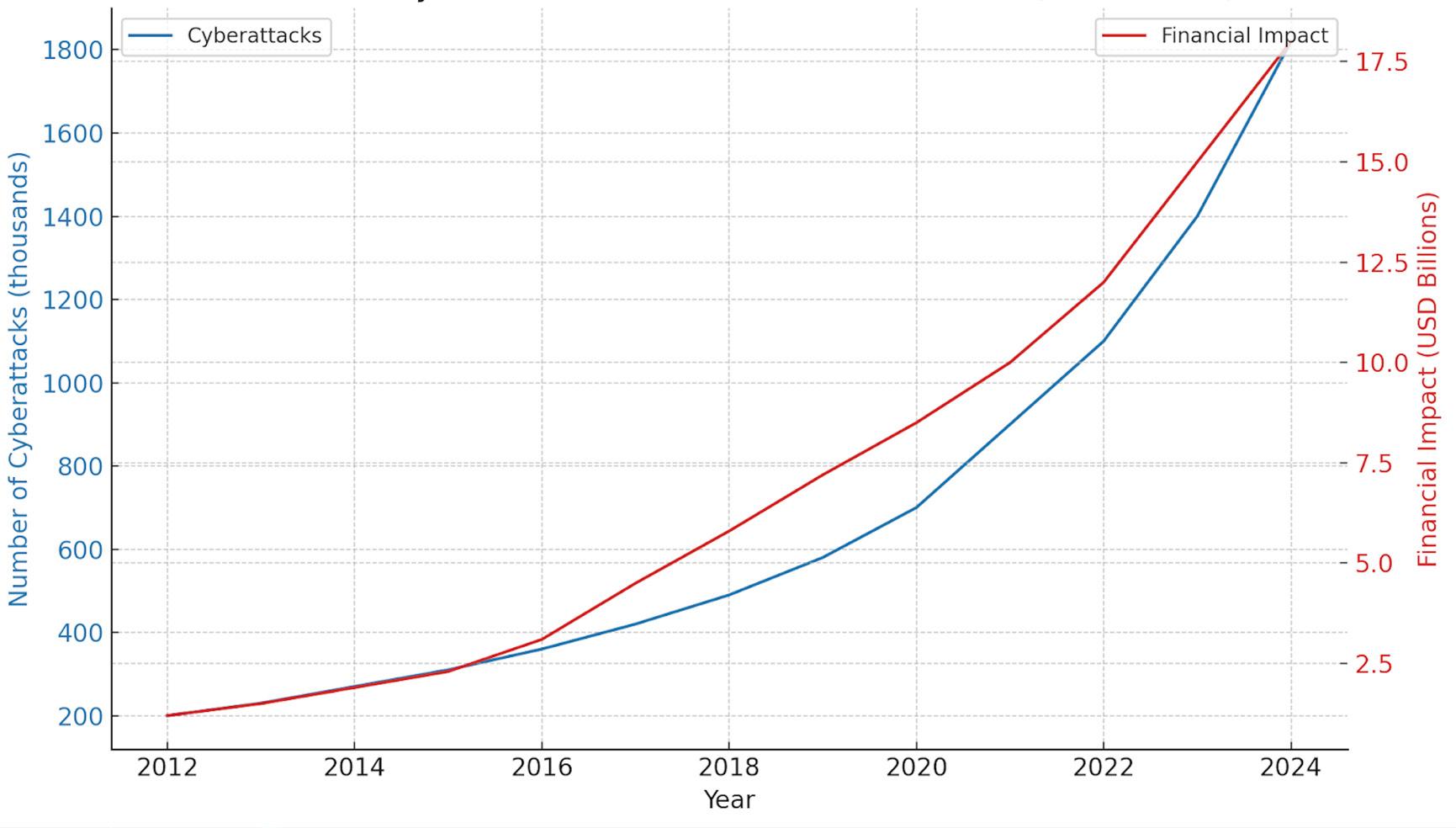
This isn’t conjecture. The rate of cyber security attacks on critical infrastructure is increasing year-over-year. Figure 1 illustrates this increasing rate of attack, and also illustrates that the financial impact of these attacks is increasing with equal velocity. In 2024, the financial impact of cyber security attacks on critical infrastructure exceeded US$17.5 billion.
The imminent threat of quantum computing to the oil and gas industry
Quantum computing, a disruptive technology, is threatening to undermine traditional encryption, exposing critical infrastructure to unprecedented risks. Proactively adopting post-quantum encryption is no longer optional – it is a strategic imperative for oil and gas operators to safeguard their operations and maintain resilience against evolving threats.
Quantum computing represents a significant leap in computing power, leveraging the principles of quantum mechanics. Unlike classical computers that process bits as either 0 or 1, quantum computers use quantum bits, or qubits, which can be in multiple states simultaneously. Additionally, qubits can be entangled, meaning the state of one qubit can depend on the state of another, even if they are far apart. Entanglement is what enables quantum speedup, giving quantum computers to the potential to solve certain problems much faster than classical computers. Full-scale quantum computers, therefore, will solve problems in economic timeframes that are impossible for classical computers.
But the ability for quantum computers to solve problems differently means they can be used differently too – and this leads to concerns. One of the significant concerns with quantum computing is its potential to break public-key cryptography, which relies on the difficulty of solving specific mathematical problems. Quantum computers will be able to solve the hard math problems we rely on for classical cryptography. For instance, algorithms like RSA encryption depend on the difficulty of factoring large numbers into their prime roots, a task that’s computationally hard for classical computers. However, quantum computers can quickly and easily
Figure 1. Cybersecurity attacks on critical infrastructure 2012 - 2024 (Figure generated using AI).2, 3, 4, 5
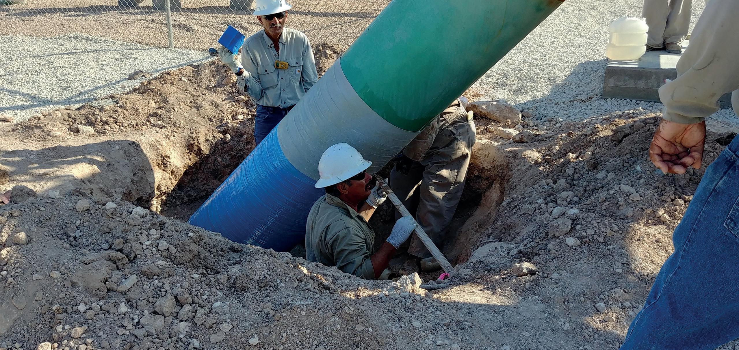
PROTECTIVE OUTERWRAPS
BUTYL TAPE WRAP SYSTEMS
LIQUID EPOXY COATINGS
PETROLATUM TAPE WRAP SYSTEMS
SOIL-TO-AIR INTERFACE
HEAT SHRINKABLE SLEEVES
INTERNAL PIPE LININGS
BITUMEN TAPE WRAP SYSTEMS
solve these problems using Shor’s or Simon’s algorithm. A cryptographically relevant (capable) quantum computer (CRQC) will crack today’s encryption, meaning what is used for encryption today is immediately obsolete.
New cryptographic techniques resistant to quantum computer cyber attacks are essential.
The national quantum action strategy
The National Quantum Strategy 6 is a comprehensive plan developed by the US government to address the challenges and opportunities presented by quantum computing. This strategy, which involves several key components, is crucial in safeguarding national security and economic interests by proactively addressing the potential disruptions that quantum computing could cause.
Research and development: promoting advancements in quantum technology and cryptography.
) Standards and guidelines: developing and adopting standards for quantum-resistant cryptographic algorithms.
) Infrastructure: preparing federal and critical infrastructure systems to transition to quantumresistant technologies.
) Collaboration: engaging with international partners and private sector stakeholders is crucial for coordinating efforts and sharing knowledge in the face of the quantum computing threat. No single entity can tackle this challenge alone. It is only through collective action and shared expertise that we can effectively transition to quantum-resistant technologies and safeguard our national security and economic interests.
The National Quantum Strategy aims to safeguard national security and economic interests by proactively addressing the potential disruptions that quantum computing could cause.
Vulnerability of national critical functions (NCFs)
The Cyber Security and Infrastructure Security Agency (CISA) identifies NCFs as essential services and functions vital to national security, economic stability, and public health and safety. The vulnerability of these functions to quantum computing largely stems from the potential breakdown of current cryptographic protections. This includes:
) Financial systems: risk of compromised encryption protecting financial transactions and sensitive data.
) Healthcare systems: threat to encrypted patient records and health information.
) Energy sector: potential disruptions to control systems and infrastructure security.
In the context of the oil and gas and energy industries, the risk category involves high exposure due to the critical nature of their operations and the complexity of their control systems. These industries rely on secure communication and data protection for operational safety,
infrastructure control, and compliance with regulations. Quantum computing could potentially:
) Compromise encryption: threatening the integrity of communications and data related to operational control systems.
) Disrupt operations: increasing risks of sabotage or operational disruptions due to compromised security systems.
) Impact critical infrastructure: affecting energy supply chains and infrastructure resilience.
For oil and gas operators, the implications of nonaction are clear:
) Compromised communications: quantum computers can decrypt sensitive communications, exposing proprietary data and operational plans.
) Disrupted operations: control systems reliant on vulnerable encryption could be rendered inoperable, leading to costly downtime and safety hazards.
) Regulatory non-compliance: emerging standards require robust cryptographic measures to mitigate quantum threats. Delayed action risks regulatory penalties and operational constraints, as well as compromising interoperability with current ecosystem participants.
The path forward for the oil and gas industry
The oil and gas industry sits at the crossroads of operational necessity and technological vulnerability. With outdated control systems and legacy software still in use, the sector is an enticing target for cyber attacks. Modernising these systems by adopting quantum-resistant encryption isn’t just a good idea – it is essential. Doing so fortifies communication channels and operational controls, ensuring that critical processes remain uninterrupted, even in the face of emerging threats.
Beyond protecting operations, there’s a financial imperative. Cyber attacks in the energy sector have already resulted in billions of dollars in losses, encompassing ransom payments, downtime costs, and recovery expenses. Investing in post-quantum encryption is a proactive measure to safeguard against these potential disasters, thereby reducing long-term financial risk.
There is also a strategic advantage for those who move early. Companies that adopt quantum-resistant technologies now are not just future-proofing their operations – they are signaling leadership and innovation. This fosters trust among stakeholders, from regulators to investors, while distinguishing the organisation in a competitive landscape.
And let’s not overlook compliance. CNSA 7 is setting the tone for federal agencies, while in parallel, standards from NIST are paving the way for the adoption of quantum-safe encryption. 8 The call to action is going out now. OnLogic is product-ready and able to upgrade existing deployments.
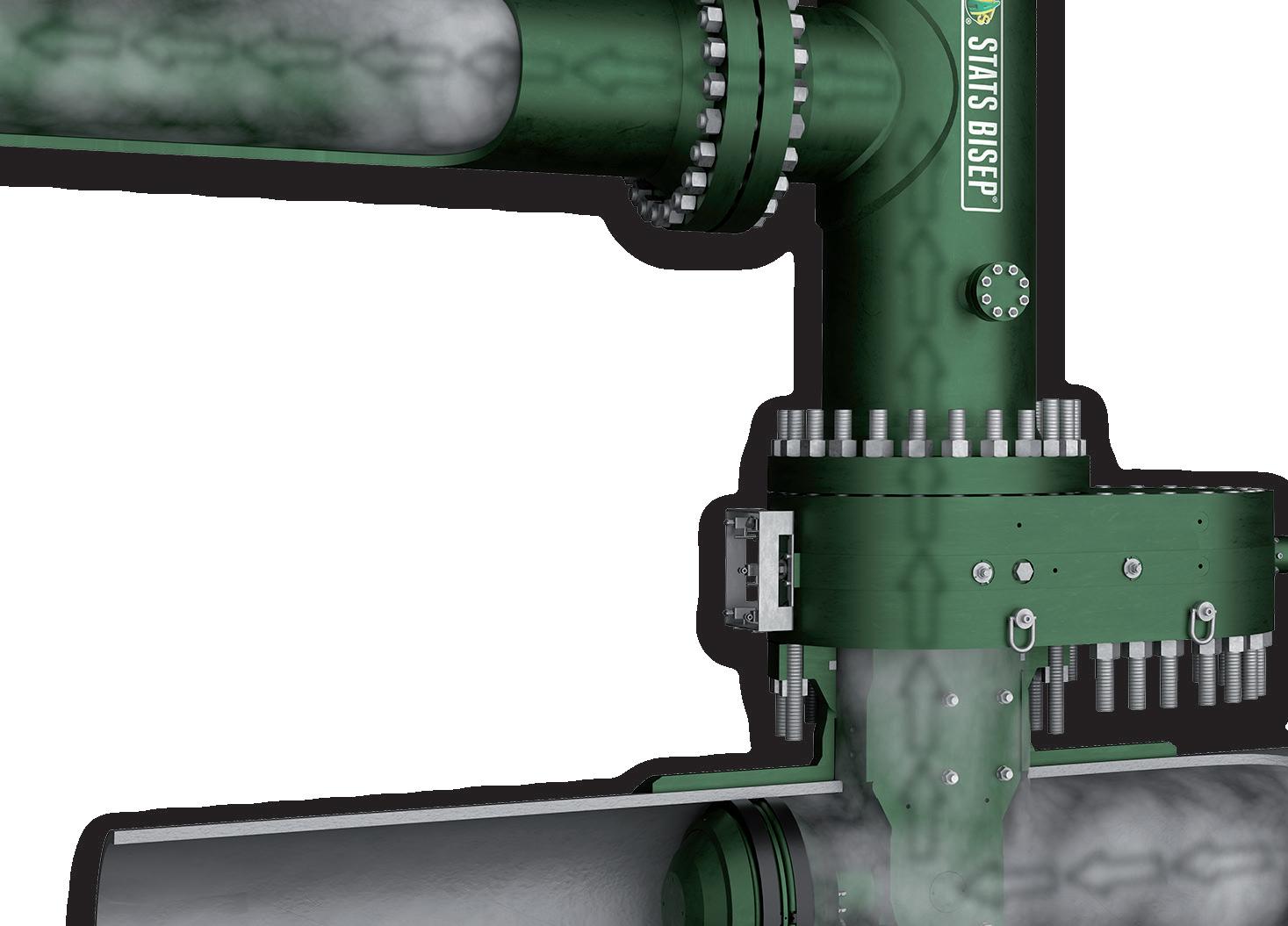
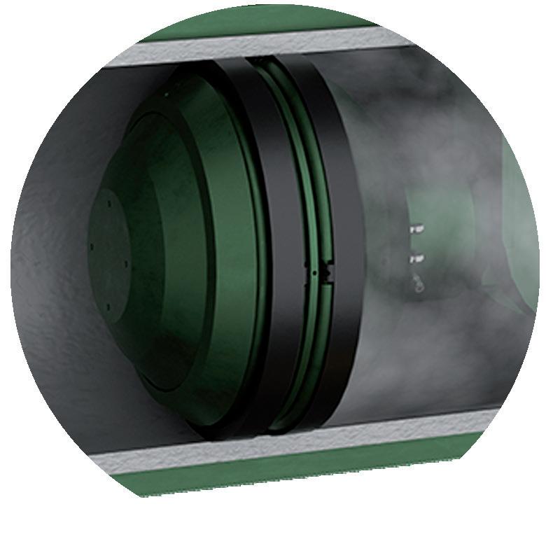
integrated bypass maintains production during isolation
Dual Leak-Tight Seals
Double Block & Bleed Isolation
Isolated Pipeline
Monitored Zero-Energy Zone
The BISEP® has an ex tensive track record and provides pioneering double block and bleed isolation while
dual seals provide tested, proven and fully monitored leak-tight isolation, ever y time, any pressure.
Taking the quantum leap: key steps for a future-ready security strategy
The journey to quantum-resilient security might seem overwhelming, but breaking it into manageable, purposeful steps can make all the difference. Here is how to chart your path:
Map your vulnerabilities
Begin with a thorough examination of your infrastructure. Pinpoint which systems are most at risk from quantum threats and assess the potential fallout of a breach. Whether it’s financial losses, operational chaos, or reputational damage, understanding the stakes will help you prioritise what demands immediate action.
Seek expert guidance
Why navigate these uncharted waters alone?
Schedule a cryptographic inventory. Almost no NCF sector company knows what cryptography it is using throughout its organisation today. It is highly likely that some of what is deployed is already disallowed, and 100% guaranteed that what is in place today cannot withstand a quantum computer cyber attack. Patero conducts cryptographic inventories and quantum risk assessments. Armed with a deep understanding of NIST-recommended encryption standards, Patero can guide you toward understanding your quantum risk and toward testing post-quantum cryptographic solutions within controlled environments, ensuring a smooth and secure rollout.
Modernise your foundation
Quantum-resistant encryption can protect outdated tech. It is time to overhaul legacy systems and upgrade hardware and software to support the future. Given AVEVA‘s long and rich history in the oil and gas automation market, supporting on-premises and cloud-based data sharing in a hybrid architecture, securing data flow from on-premises to cloud is paramount. Oil and gas operators maintain an average of 20+ years of experience working with historical data sets on-premise and now in the cloud. 9 Seamlessly embedding quantum-safe protocols into your existing communication and control systems is not just smart, it is essential.
Operational platform providers like AVEVA have integration with many systems and can adapt to hybrid scenarios that allow oil and gas operators to take advantage of emerging technologies, like Patero’s quantum-resistant software to protect PI System operations and assist customers to leverage existing ISO standards, like 27001, 9001, and SOC2.
Build strategic alliances
Success in this transition is a team sport. Collaborate with specialists like Patero, whose tools and know-how can make your quantum journey not only achievable
but effective. These partnerships will keep you ahead of emerging threats and aligned with best practices, turning potential risks into managed challenges.
Empower your people
Even the most advanced technology is only as effective as the people behind it. Invest in your team by equipping them with the skills and knowledge needed to master quantum-resistant systems. From IT staff to leadership, ensure that everyone understands the significance of this transition and their role in securing your organisation’s future.
Conclusion: build resilient, future-ready infrastructure
As the race toward quantum computing accelerates, the oil and gas industry faces a critical juncture. Operators must act decisively to adopt post-quantum encryption, safeguarding their operations and securing their position in a rapidly evolving landscape. By investing in modern, quantum-resistant technologies today, the industry can ensure continued resilience and operational excellence for decades to come.
The move to post-quantum cryptography isn’t just a technical shift; it is a bold step into the future of security. With clear priorities, trusted partners, and empowered teams, you’ll not only meet the challenge, you’ll redefine what is possible. Leveraging Patero’s post quantum cryptography as a means of ensuring compliance with post-quantum cryptographic standards and broader cyber security requirements is a solid start and involves a systematic approach.
By tackling these challenges head-on and taking deliberate steps toward quantum-resistant security, oil and gas operators can protect their operations, mitigate financial risks, and position themselves as leaders in a rapidly evolving technological landscape. The time to act is now.
References
1. FBI director warns Chinese hackers aim to ‘wreak havoc’ on US critical infrastructure, (2024). Retrieved 31 January 2024, from https://www. nbcnews.com/politics/national-security/fbi-director-warn-chinesehackers-aim-wreak-havoc-us-critical-infrastr-rcna136524
2. FBI Warning on Chinese Hackers – NBC News article: FBI director warns Chinese hackers aim to ‘wreak havoc’ on US critical infrastructure, (2024). https://www.nbcnews.com/politics/national-security/fbidirector-warn-chinese-hackers-aim-wreak-havoc-us-critical-infrastrrcna136524
3. National Quantum Strategy – Official US Government publication: National Quantum Strategy, (2025). https://www.quantum.gov/strategy/
4. CNSA 2.0 Cryptographic Standards – US Department of Defense: Commercial National Security Algorithm Suite 2.0 (CNSA 2.0) FAQ, (2022). https://media.defense.gov/2022/Sep/07/2003071836/-1/-1/0/ CSI_CNSA_2.0_FAQ_.PDF
5. NIST Quantum-Resistant Cryptography Timeline – CSO Online coverage: NIST publishes timeline for quantum-resistant cryptography, but enterprises must move faster. https://www.csoonline.com/ article/3604824/nist-publishes-timeline-for-quantum-resistantcryptography-but-enterprises-must-move-faster.html
6. National Quantum Strategy, (2025). Retrieved 10 August 2025, from https://www.quantum.gov/strategy/
7. https://media.defense.gov/2022/Sep/07/2003071836/-1/-1/0/CSI_ CNSA_2.0_FAQ_.PDF
8. https://www.csoonline.com/article/3604824/nist-publishes-timelinefor-quantum-resistant-cryptography-but-enterprises-must-move-faster. html
JANUARY
19-22
The industry ’s only forum devoted exclusively to pipeline pigging for maintenance and inspection
This event will draw engineering management and field operating personnel from both transmission and distribution companies concerned with improved operations and integrity management.
INTERNATIONAL CONFERENCE
Technical papers will cover ILI data assessment, prioritization of repairs, new tools, improving tool per formance, external coating inspection with ILI tools, pig launch and receiving systems, new regulations and much more.
E XHIBITION
Visit one- on- one with the world’s top providers of pigging, ILI, and integrity management ser vices – over 170 companies will be represented.
TECHNICAL TR AINING COURSES
12 in-depth, technical pipeline training courses will be held prior to the conference and exhibition. Upskill your workforce for 2026.
Steve Jones, Business Director of Alternative Fuels, Luxfer Gas Cylinders, explores the short-term requirements to harness hydrogen’s full value, and the road to a safe and sustainable hydrogen network.
In the UK, hydrogen has potential to decarbonise heavy industry, transport, and power generation, and is being positioned as a cornerstone of the country’s future energy mix. Government investments and targets intend to push the UK to the forefront of the global hydrogen
economy, with billions committed to infrastructure and innovation.
Yet, while momentum is building, the safe, reliable, and sustainable delivery of hydrogen is still a complex challenge.
This article explores the short term requirements to harness hydrogen’s full value – which involves not only new infrastructure, but also advances in materials, corrosion control, maintenance strategies, inspection technologies, and flexible transport.
Establishing a hydrogen infrastructure fit for the future
The UK’s existing gas distribution network stretches over 300 000 km – enough to circle the Earth seven times. Many believe repurposing this network to carry hydrogen could be a low-disruption path to connect production sites with storage facilities and major industrial hubs. However, adapting the existing gas grid is far from straightforward. Hydrogen has different physical properties to natural gas: it’s lighter, more reactive, more prone to leakage, and can cause embrittlement in some metals. This means that existing pipelines, seals, valves, and monitoring systems would need substantial upgrades to maintain their safety and integrity whilst servicing hydrogen.
In a report, the Committee on Climate Change warned that the UK’s hydrogen pipeline network won’t fully serve industrial clusters until after 2030.1 This delay reflects not just the engineering challenges but also the regulatory, investment, and planning obstacles involved.
Challenges to hydrogen pipeline readiness and durability
In traditional underground pipelines, lifespan is measured in decades, often 40 - 80 years if corrosion is controlled. Longevity depends on three main factors: material selection, corrosion control, and effective maintenance regimes.
On the first point, hydrogen’s small molecular size means it can diffuse into metals, potentially leading to hydrogen embrittlement, which weakens the metal’s microstructure and reduces its load-bearing capacity. Certain materials, such as carbon composites, can resist these effects. As for corrosion control and effective maintenance regimes, the problem is obvious: lines are buried up to 6 ft deep, often in moist earth. Moreover, any repairs and decommissioning of the pipelines will require gaps in hydrogen supply to usage sites which, if too frequent, risk damaging confidence in hydrogen as a viable alternative to traditional fuels.
The time and expense required to source the appropriate materials and repurpose the existing gas pipelines will leave users and suppliers with at least five years to wait for a reliable infrastructure to plan their hydrogen projects around.
The role of virtual gas pipelines
While permanent hydrogen pipelines will be vital for the UK’s long-term infrastructure, bulk gas transportation (BGT) systems can operate as ‘virtual gas pipelines’. A key focus for Luxfer Gas Cylinders, these virtual supply solutions can provide a crucial link between supply and demand, serving as a safe and reliable solution until permanent pipeline infrastructure is in place.
Instead of permanent buried pipes, these are aboveground, modular units of hydrogen housed in protective frames. Longevity depends on cylinder lifespan, but the cost of maintenance and decommissioning is a fraction of what it would be for traditional pipelines. While fixed pipelines require significant disruption and expense to replace sections after decades of service, BGT components can be individually replaced, upgraded, or redeployed as technology advances. This modularity means asset life can be extended without replacing the entire transport system.
Innovation in this area has been driven by demand across different sectors, industries and markets, and Luxfer Gas Cylinders is among the companies pioneering in this space.
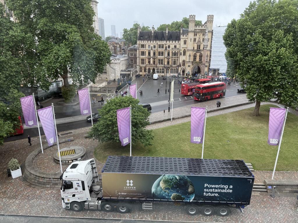
The company’s Multiple Element Gas Containers (MEGCs) – developed at a purpose-built alternative fuel facility in Nottingham – are designed specifically to meet the needs of large-scale requirements for hydrogen, allowing over 1 t of the gas to be safely stored and transported.
Available in 20 ft, 40 ft, and 45 ft units, MEGCs offer maximum capacity and energy delivery, and optimise Total Cost of Ownership. Whilst Type I steel tube trailers hold 380 - 500 kg of hydrogen – and older models as little as 100 kg of hydrogen – Type IV composite trailers can carry up to 1000 kg of hydrogen. Delivering this volume of gas per load significantly reduces vehicle movements and the number of units on the road. Fewer trips mean lower operational costs, reduced fuel consumption, and decreased CO2 emissions, making hydrogen transportation more efficient and sustainable.
Figure 1. Luxfer G-Stor® Hydrosphere Multiple Element Gas Container (MEGC).
PIPELINE SAFETY MANAGEMENT SYSTEM ASSESSMENT PROGRAM
Enhances safety and operations A commitment to a culture of safety and continuous improvement
Provides shared learnings and benchmarking across the industry
Strengthens safety management systems for individual operators
To learn more and take the first step toward your assessment visit:
date, this is the largest environmental investment in the Ukrainian industry since Ukraine’s independence.
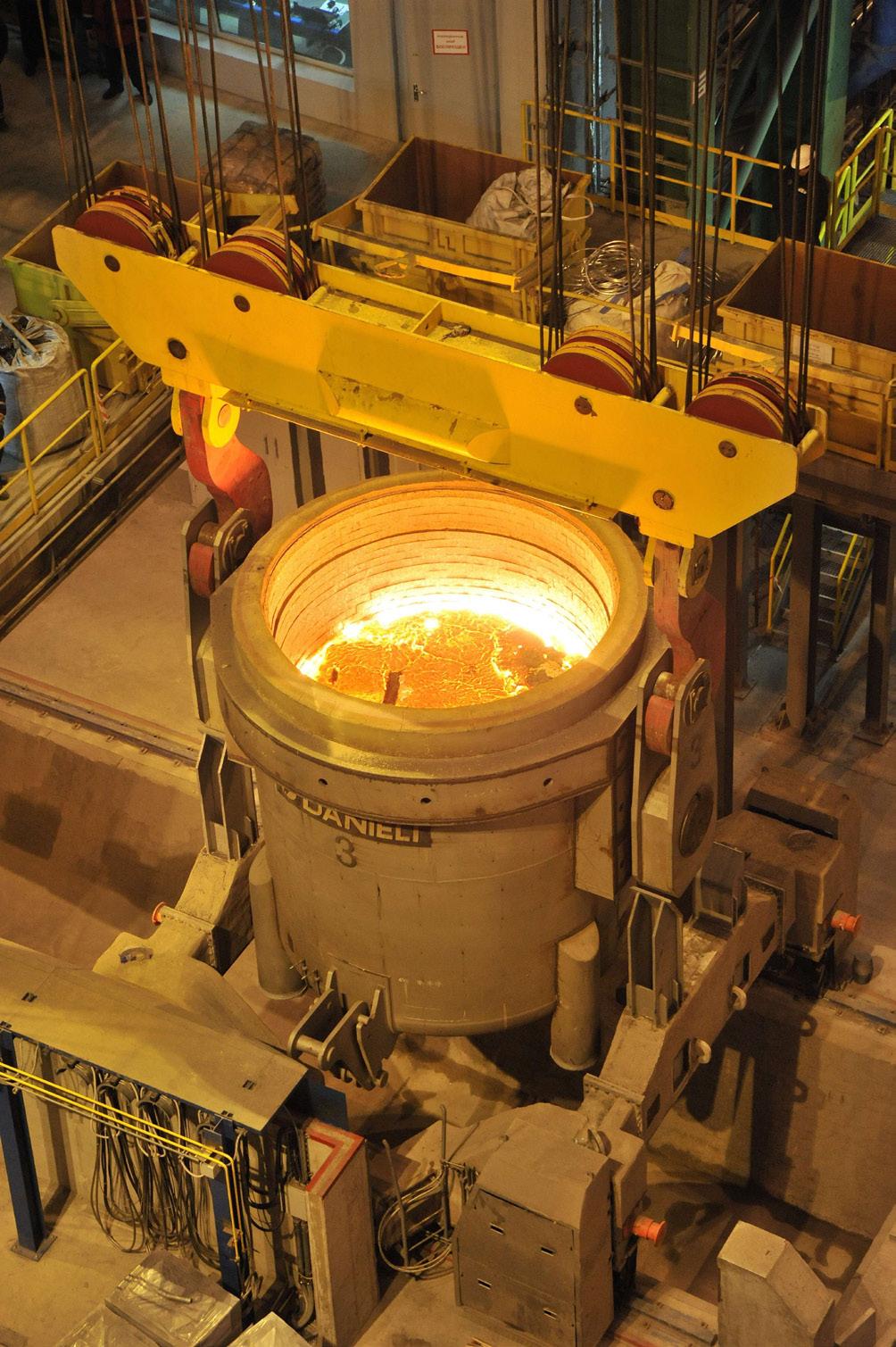
The launch of Interpipe Steel allowed the company to close its ‘dirty’ open-hearth production and reduce specific CO 2 emissions into the atmosphere by 10 times, and emissions of harmful substances by 2.5 times. In 2024, Interpipe reduced specific CO 2 emissions per ton of seamless pipes by 61%, compared to 2010 levels, outperforming 2030 EU targets, with the direct CO 2 emissions under 200 kg/t. Built in accordance with the strict environmental requirements of the EU, this metallurgical plant is now the flagship of green metallurgy in Ukraine and Eastern Europe.
Electric arc steelmaking not only reduces emissions but also ensures recycling, meaning that scrap is 100% recycled. In the context of the green transition, this concept remains the most advanced steelmaking method globally.
Integration with EU pipeline projects
Although Scope 3 emissions are challenging to manage, one thing is clear: the ultimate goal of measuring and tracking them is to inform business decisions that reduce
climate impact, including those along the supply chain. This involves establishing a performance baseline and setting priorities and targets in collaboration with suppliers.
Compared to many pipe manufacturers that have no steel production of their own and must purchase and deliver steel billets to their facilities, Interpipe has a full-cycle production facility located close to each other. This includes the EAF, scrap collecting and processing mill, as well as hot rolling floors, threading and finishing lines for pipe production. Such a location of assets allows for reducing carbon footprint and avoiding double CO 2 emissions: during production and transportation.
Vertical integration
Vertical integration is a priority within the leadership component and is aimed at strengthening control over the entire value chain, from the procurement of materials to the production of finished goods. Such strategic integration allows the Interpipe Group to effectively manage supply chain risks, increase delivery reliability, and maintain control over all technological stages. Vertical integration also ensures better coordination between production, logistics, and commercial functions, leading to a faster response to customer needs and market changes. The business segment of scrap metal procurement and processing, as well as steel production, is a key element of vertical integration. Steel production has strategic importance, as it supplies round steel billets for Interpipe’s other two business segments – pipe manufacturing and railway products. This provides the following competitive advantages:
) Control and reduction of scrap procurement costs for final product manufacturing.
) Control and quality management at all critical stages affecting the properties of the final product.
) Control and management of pollutant emissions.
) The ability to quickly develop new products with integrated solutions, including new steel grades and production technologies, significantly contributing to the strategic goals of the pipe and railway segments in creating high value-added products.
The role of circularity in decarbonisation
Circularity is a cornerstone of reducing the impact of anthropogenic activities. It entails lifespan extension of products by recycling, reducing, and reusing the resources used to create steel. In a coherent circular economy, the steel industry has substantial competitive advantages over other materials. This is due to steel’s inherent properties, making many of the circular economy principles already well-established.
Since 1900, the global steel industry has recycled over 25 billion t of steel, which allowed to reduce iron ore consumption by around 33 billion t and cut coal consumption by 16 million t. The energy use has also been significantly reduced. Nowadays,
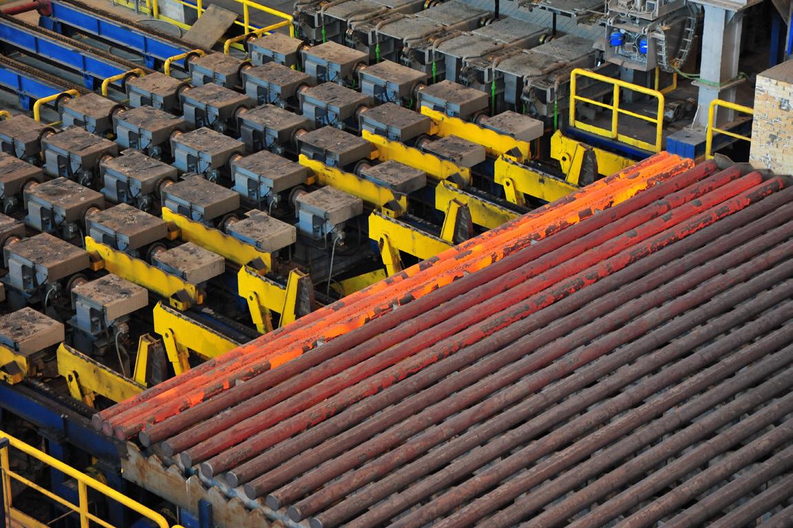
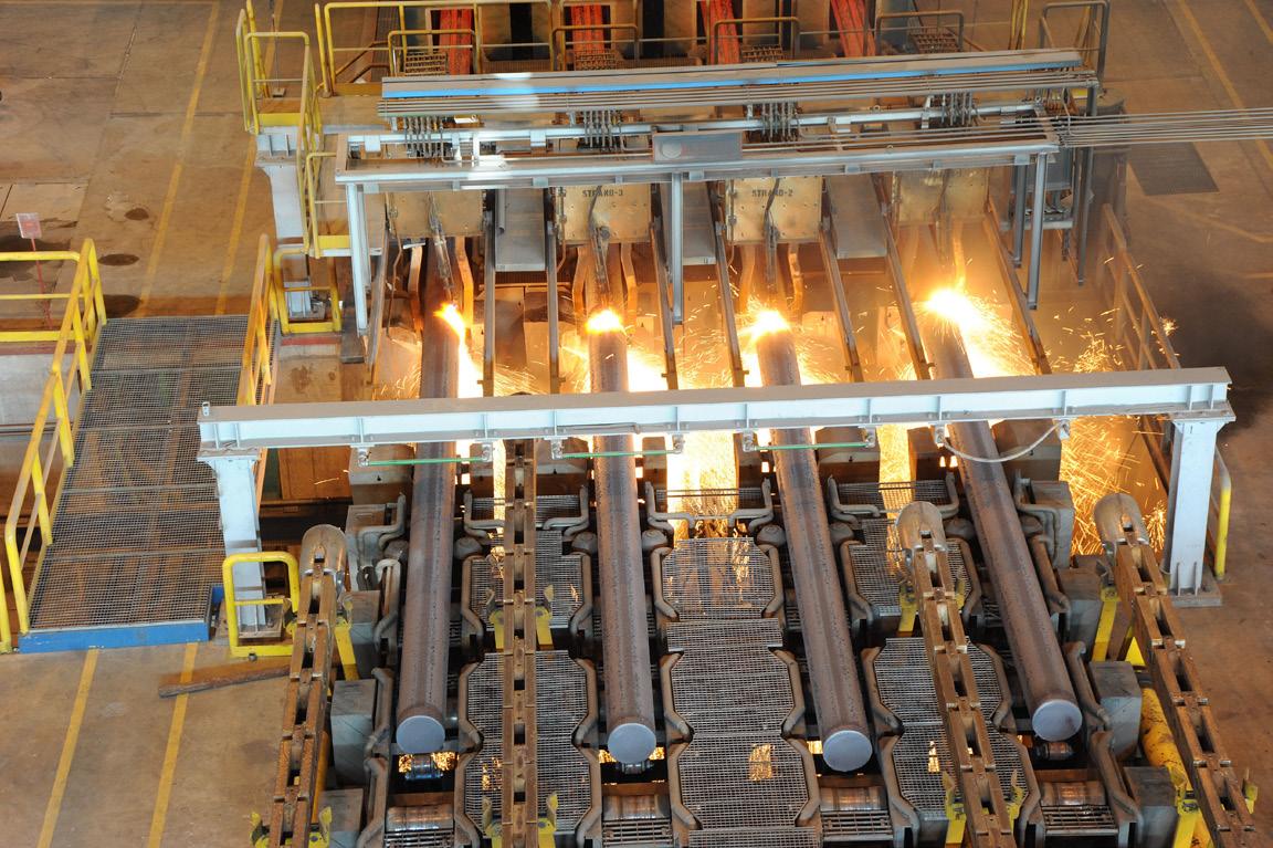
Figure 2. Cooling and roller conveyor system at Interpipe Steel.
Figure 3. Interpipe Steel continuous casting machine.
1 t of steel production requires only 40% of the energy, compared to 1960.
Today, resource efficiency is a core component in the modern steelmaking process. The main goal is to use all raw materials to their full capacity, which guarantees that every co-product, such as slag, manufactured during steelmaking, is reused in new products.
In Interpipe’s case, the company successfully mitigated the impact of anthropogenic activity on the environment through the introduction of innovative technologies. It integrated the closed water supply cycle, allowing the reuse of the wastewater without polluting rivers and other water bodies.
In Interpipe’s EAF production, cleaning systems collect gas and dust generated during steel production and deposit them in filters for granulation. In addition, the electric arc furnace at Interpipe Steel is equipped with a special enclosure known as a Doghouse. It serves to isolate the noise generated during the scrap melting process. Thanks to its unique design and sound-absorbing materials, the Doghouse provides comprehensive noise insulation for the unit during operation.
As a result, noise levels do not exceed the legally established limits – 45 dB at night and 55 dB during the day. The plant’s noise insulation efficiency has been confirmed by the British company ERM and verified by both district and city sanitary authorities. Additionally,
the company is increasing the share of carbon-neutral electricity, including nuclear, hydro, and renewable sources.
However, when the methodology for measuring Scope 1 - 2 emissions remains relatively clear, measuring Scope 3 emissions still requires additional efforts.
Long-term benefits for pipeline operators
To stay competitive, manufacturers should prioritise traceability, transparency, and energy efficiency. Products made using renewable energy and advanced low-carbon processes will have an edge over those from companies that neglect decarbonisation procedures.
Measuring and verifying carbon footprints builds trust with clients and partners, while collaborating with compliant, sustainable partners reduces risk and improves reliability. Combined with clear legislation and a smart regulatory approach, these measures enable manufacturers to move toward a greener, more sustainable future.
Bibliography
• CBAM https://www.energymonitor.ai/carbon-markets/as-eu-carbonborder-levy-looms-businesses-scramble-to-get-ready/?cf-view
• DENG, Z., ZHU, B., DAVIS, S.J. et al. Global carbon emissions and decarbonization in 2024.Nat Rev Earth Environ 6, 231–233 (2025). https://doi. org/10.1038/s43017-025-00658-x
• https://eba.com.ua/en/cbam-mozhe-postavyty-pid-zagrozu-integratsiyuukrayiny-v-yes/
• https://www.eunews.it/en/2025/02/07/green-deal-simplification-reachesthe-cbam/
• https://www.ft.com/content/44f56758-9158-4b40-b59a-b2ffe6fc74ba
• https://worldsteel.org/wider-sustainability/circular-economy/
Gustavo Romero, Ilze Priego, and Juan Carlos Gomez, Penspen, debate possible engineering solutions to the hidden challenge of dust that can impede gas pipeline performance.
Dust – an inconvenience in our day-to-day lives, but a serious risk in the operation of gas pipelines if not managed appropriately. This will discuss how to assess the presence of dust and present a six-stage methodology for mitigating its impact on transmission and distribution systems.
Is dust truly a threat to the safe and optimal operations of our gas pipelines? As it is a consequence of a previous process, the presence of dust is not currently defined as a direct threat by the Pipeline Research Committee International (PRCI), who analysed and classified 22 root causes representing the most common threats to the integrity of pipelines and facilities. Instead, it could be included as part of the threat of corrosion and/or erosion, equipment failures, and/or incorrect procedures during construction, operation, and maintenance. The US Department of Transportation does not classify dust as a specific hazard class, however, it acknowledges that its presence in gas pipelines could affect the overall hazard classification of the transported gas due to the increased risk of ignition, fires, and/or explosions. Similarly, the Canadian Energy Regulator (CER) focuses on preventing risks such as explosions due to the presence of dust and ensuring worker safety, rather than on specific dust levels. In Mexico, the Mexican Official Standards (NOM) do not have specific requirements for dust management. They only state that delivery gas must be technically free of water, oil, liquid hydrocarbons, solid materials, dust, gums, and other gases that could affect transportation, storage, and distribution systems or downstream equipment or facilities.
That said, the presence of dust and residues in natural gas processing, transportation, and distribution systems has been reported and investigated by many companies, especially due to the negative consequences they can generate at different stages of the gas distribution process. In gas pipelines, dust can contaminate the product, which can lead to operational interruptions or poor quality in raw materials used. It can also affect the accuracy of instrumented internal inspection tools. Most critically – with contamination from mercury and naturally occurring radioactive materials, such as radioactive Pb210,1 and potentially
pyrophoric materials such as iron sulfides – dust in pipelines can pose a serious risk to health and the environment.
Phased assessment methodology
Having developed numerous projects with gas transportation and distribution companies and considering the teams’ specialist knowledge, best practices, and global experiences in dust management, Penspen have proposed a methodology for assessing the presence of dust, its potential sources, and alternative solutions to control or mitigate its negative impact on pipelines and downstream equipment.
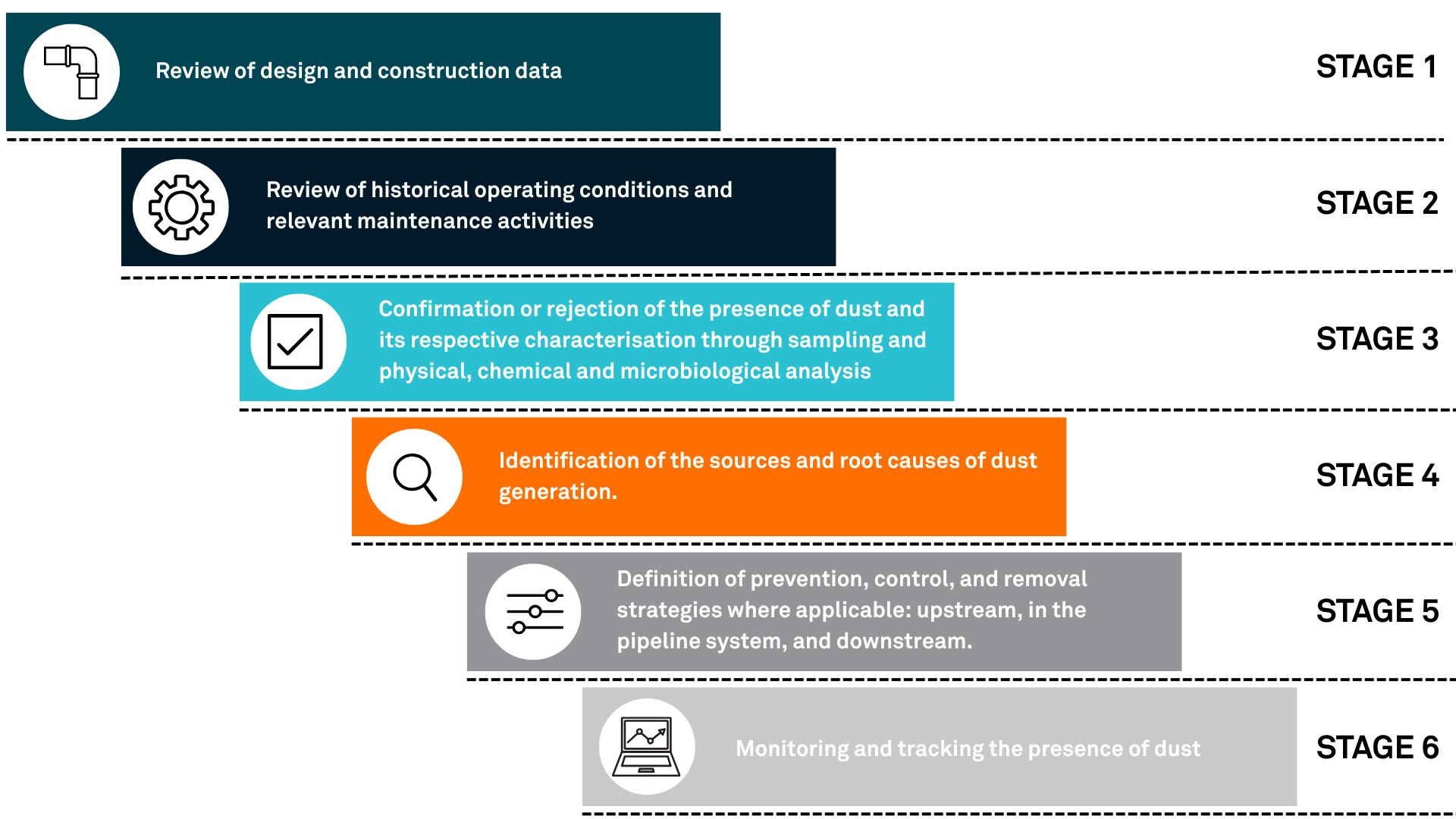
The methodology requires the participation of a multidisciplinary team that includes design, operation, and maintenance personnel from the pipelines included in the scope of the dust assessment, and proposes a six-stage approach (Figure 1).
Stage 1: design and construction review
Design and construction data are critical to addressing dust hazards. The following (and other) date can be very helpful when investigating and analysing dust hazards:
) Steel grade (API).
) Diameter.
) Thicknesses.
) Pressures and temperatures.
) Calculations.
) Route and length.
) Fittings such as valves.
) Changes in direction and topographic profile.
) Flow rate.
) Gas capacity and composition.
) Internal coating type (when applicable).
) Filtration equipment specifications.
Stage 2: operation and maintenance history
Reviewing and analysing historical operating conditions such as internal pressure and temperature profiles, ambient temperature, start-up, moisture content, inlet gas composition, changes in operation, operating context, and variations in demand and flow rate over time have a significant impact on the corrosion phenomenon.
Stage 3: presence of dust, sampling, and characterisation
Dust can be wet or dry and is composed of various types of ferrous and non-ferrous elements and compounds. It is typically detected during internal mechanical and/or chemical cleaning programmes, during scheduled equipment maintenance, or when problems arise in downstream equipment, such as filter blockage and collapse, instrumentation and valve obstruction, or accelerated valve deterioration due to erosion and corrosion. This dramatically increases maintenance activities and, in the worst case, can lead to failures requiring partial or total system shutdown.2 It is essential to plan dust sampling for physical, chemical, and microbiological characterisation.3 The following are some of the main parameters to consider, but are not limited to:
) Operational information at the time of sampling.
) Quantity collected.
) Colour and appearance.
) Hardness and particle size.
Figure 1. Penspen dust presence methodology.
) Chemical composition (elements and compounds). ) Bacterial activity (counting and identification).
Sampling can be completed as part of internal mechanical cleaning activities at receiving traps; during maintenance on equipment upstream and/or downstream of the pipeline; during opening of permanent or temporary filters for cartridge changes, or in separation drains, among other locations. The most important element is to try to preserve the sample under conditions that minimise the alteration of the compounds.
The varying colours of dust powders will depend upon the composition of the compounds and residues present. For example, magnetite (Fe3O4) or rust is usually black, while hematite (Fe2O3) can be black or red depending on the particle size. Geotite (g-FeOOH) can also be black or dark grey. Greigite (Fe3S3) and siderite (FeCO3) probably give the powder a reddish colour.4 Salt (NaCl), sand, quartz (SiO2), and calcite (CaCO3) give a lighter hue, usually in the grey scale. The powder that has gained the greatest notoriety is known as ‘black powder’. This is due to its visual appearance, with the dark grey or black tone typically associated with iron sulfide compounds, as well as magnetite.
Once the samples have been collected and preserved to avoid contamination, they are sent to a laboratory where tests or analyses can be performed for classification. These can include:
) Visual inspection using a macroscopic magnifying glass.
) Hardness: microhardness and/or nanoindentation.
) Composition: x-ray diffraction, fluorescence spectrometry, thermogravimetric analysis, scanning electron microscopy.
) Bacterial count: serial dilution.
Powder particles are irregular and harder than many engineering materials used in pipes and piping components, so they can be highly erosive. For example, in a study using the Vickers microhardness technique, the hardness of Fe3O4 powder particles were measured to be equivalent to 52 Rockwell C, compared to 89 Rockwell B for carbon steel.5
Particle size and distribution are critical to addressing dust contamination once it has formed. Pipeline operators have reported that dust can be composed of different particles ranging in size from as small as 0.01 μm to as large as 1000 μm. However, most studies have reported the average particle size to be between 0.1 μm and 300 μm. Particle size and distribution allow operators to specify filtration equipment, ensuring the highest possible retention of these particles before they enter other process steps.6
Pipeline operators have reported varying dust compositions, even within the same pipeline system. Dust composition depends on operating conditions; geographic location; the elements and compounds of the underground formation; the type of hydrocarbon; the type of facility/process; the compounds/chemicals introduced, and other factors such as entrainment. Dusts are primarily composed of various forms of corrosion products, typically iron sulfides, iron oxides, and iron carbonate, mechanically mixed or chemically combined with any number of
contaminants such as salts, sand, liquid hydrocarbons, metallic waste, and steel mill scale. Typically, corrosion products constitute more than 80% of the dust by weight, with the remaining 20% being contaminants.6
The non-ferrous compounds present in dust are numerous and variable. Elements such as manganese, copper, nickel, titanium, carbon, vanadium, magnesium, zinc, chromium, and others may be present in producing formations, introduced by hydrocarbons and formation water, accumulated as a result of corrosion and abrasion of piping and facility materials, or as process remnants (e.g. catalysts), and introduced as broad-spectrum chemicals in other processes. Chlorine, sodium, silica, phosphorus, silicon, and others are also commonly present.5
Naturally Occurring Radioactive Material (NORM), which includes radionuclides such as uranium, thorium, radium, lead (Pb-210), polonium (Po-210), and their decay products, may be present in gas pipelines. The concentration and type of NORM varies depending on the source of the natural gas and associated processing activities.1
Corrosion is the most common cause of all forms of dust, however, determining the amount of dust that can be expected is a much more complex phenomenon as it is strongly affected by a multitude of factors:
) Water condensation.
) Fluid velocity.
) Temperature and pressure.
) Topographic profile.
) Seasons of the year.
) Demand variation.
) Changes in gas sources and/or composition.
) Pipeline dimensions.
) Contamination from maintenance.
) Pipeline system expansions.
) Cleaning and internal inspection campaigns.
Stage 4: potential sources of dust in pipelines
Although the origins of dust are still unclear, some of the main known sources include:
) Upstream of the process:
• From wells.
• Carryover.
• Moisture from lateral components.
• From maintenance and/or construction work.
) From internal processes in the pipeline:
• Ingress of water used for hydrostatic testing.
• Prolonged exposure of pipeline segments to the atmosphere or any other source of fresh or salt water during storage, transportation, and installation.
• Water condensation.
• Microbiologically Induced Corrosion (MIC).
• Erosion inside the pipeline.
• Carryover.
Root Cause Analysis (RCA) is a widely used reliability methodology for identifying the causes of an undesired event. In the context of this article, an undesired event refers to the presence of dust; equipment failures due to dust; excessive amounts of dust or loss of effectiveness of internal inspections with inline inspection (ILI), among other cases. Penspen has developed its own RCA methodology, which has been successfully used to identify the root causes of dust. Based on the use of fault trees, the methodology includes the following steps: formation of a Natural Work Team; problem identification; functional analysis; evidence collection; tree construction; root cause identification; conclusions, and recommendations.
Stage 5: prevention, protection, and/or removal methods
Combatting the presence of dust in gas pipelines comes down to three approaches: prevention, control, and/or removal. The appropriate selection of these methods will depend on a thorough understanding of the composition and properties of dust, as well as its origin and formation mechanisms.7 In most cases, a combination of techniques and methods is required.
Stage 6: monitoring and tracking the presence of dust
Despite these challenges, operators must continue transporting and distributing gas when dust is present in their systems. It is therefore vital that they use devices to monitor the presence and quantity of dust in real-time to identify critical changes that could lead to a major issue. Dust sampling and laboratory analysis, such as inlet gas characterisation with emphasis on moisture content and aggressive species such as CO2, H2S, and O2, are also essential. Operational parameters must be considered, and using digital tools such as data management dashboards can be an excellent way to track and control dust data.


Pipeline integrity management systems require the operator or person responsible for the operation to define their operation and maintenance plans and programmes based on risk. By correlating variables and comparing them with established limits or ranges in the form of operational integrity windows, operators can put in place effective plans for managing dust in their pipelines.8
References
1. MARCUS, J., & Col. Journal of Environmental Radioactivity. Pb 210 Content in Natural Gas Pipeline Residues (‘Black-Powder’) and its Correlation with the Chemical Composition. Brasil, 2005.
2. EL-SHERIK, M., & Col Assessment of Black Powder Concentrations in Natural Gas Pipeline Networks, Khalifa University, United Arab Emirates, 2018.
3. VENKATADRI, R., & Col. Analyses of Black Powder in Natural Gas Pipeline. Paper No: C2011-11088 2011.
4. SHERIK, A.M., ZAIDI, S.R., TUZAN, E.V. and PEREZ, J.P., Black Powder In Gas Transmission Systems.
5. SHERIK, A.M., Black Powder in Gas Pipelines, Saudi Aramco. Technical Paper IBP1599_09 Rio Pipeline 2009 Conference & Exposition, Brazil.
6. SHERIK, A.M., Managing Black Powder in Gas Transmission Pipelines. Research and Analytical Services Department, Saudi Aramco, Saudi Arabia.
7. EL-SHERIK, M. Strategies for Managing Black Powder in Sales Gas Pipelines. Pipeline & Gas Journal. Saudi Aramco, 2018.
8. Integrity Operating Windows. Edition: 2 API RP 584Edition. 2021.
Max Wedekind, Managing Director, DENSO Group Germany, highlights new developments in sustainable corrosion protection for pipelines in the oil and gas industry.
In pipeline construction, corrosion protection plays a central role in the safety, cost-effectiveness, and environmental compatibility of the applied systems. Sustainable corrosion protection aims to guarantee the service life of pipelines for decades – while minimising their ecological footprint. With SEALID® All-in-1, DENSO Group Germany offers a globally unique, universally applicable corrosion protection solution that surpasses standard products in terms of simplicity, safety and sustainability. This article compares corrosion protection methods in terms of cost efficiency, workload, material usage and CO2 savings.
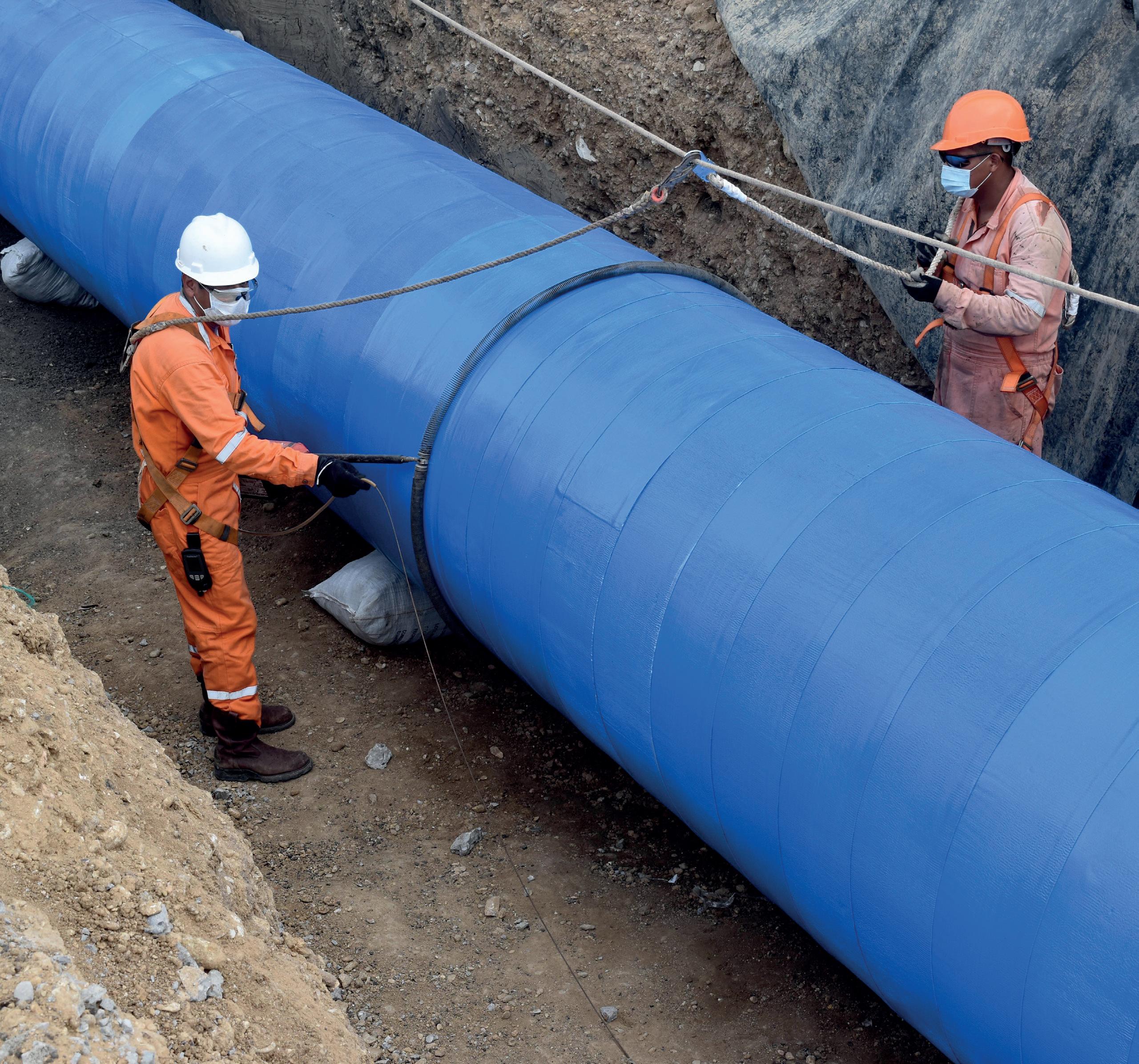
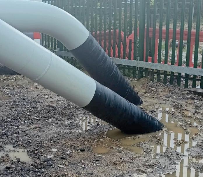
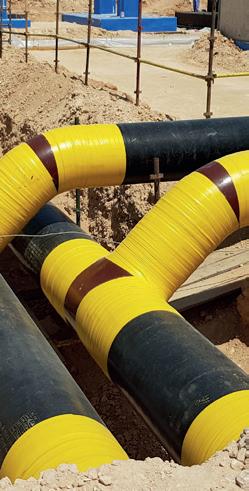
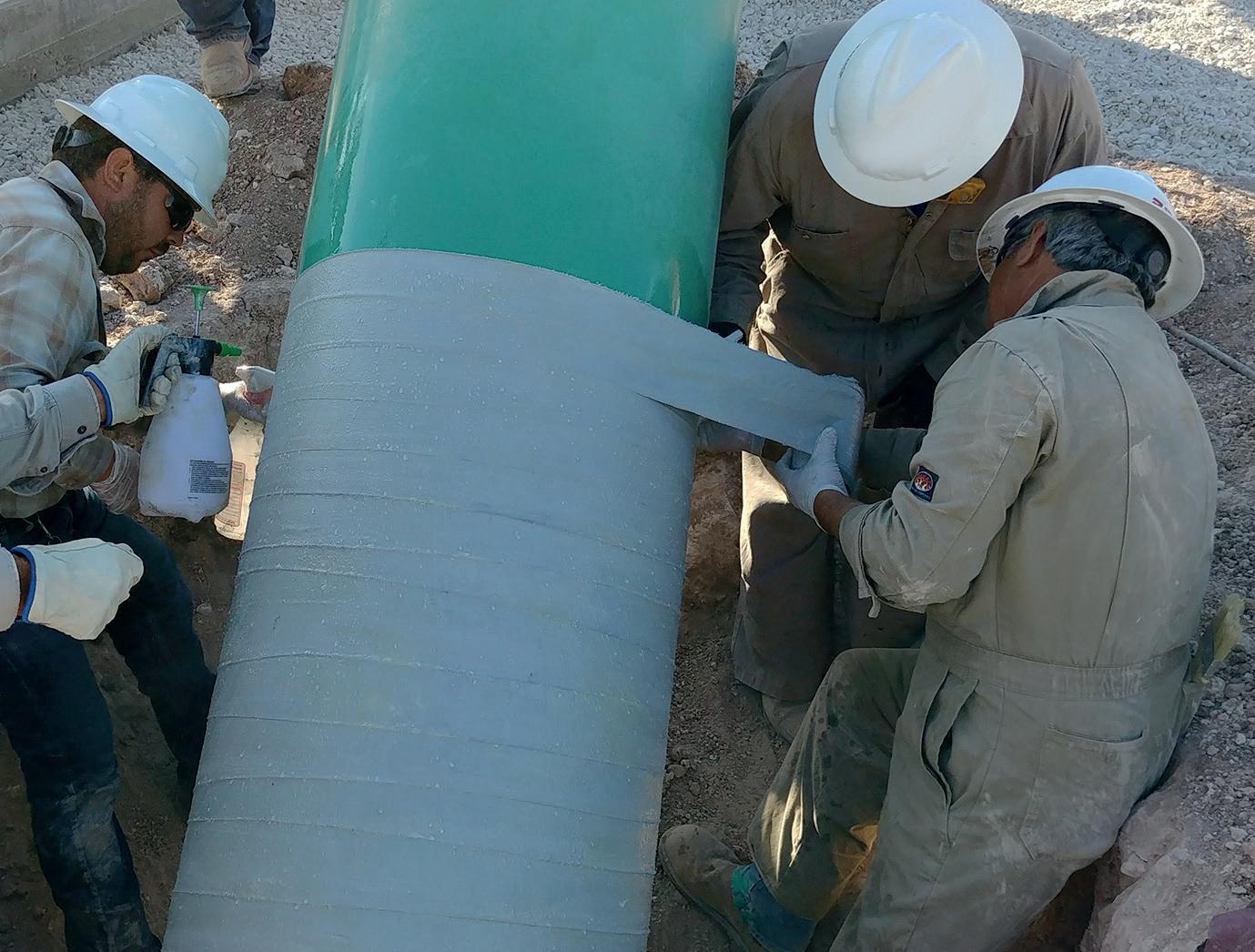
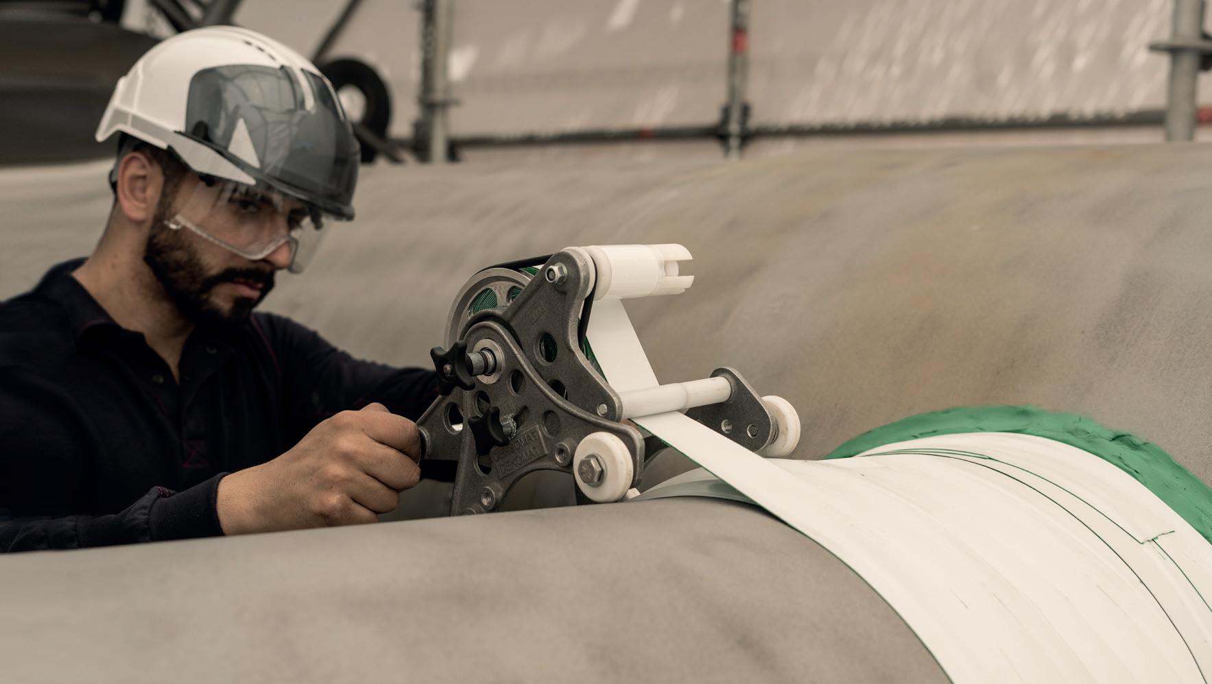
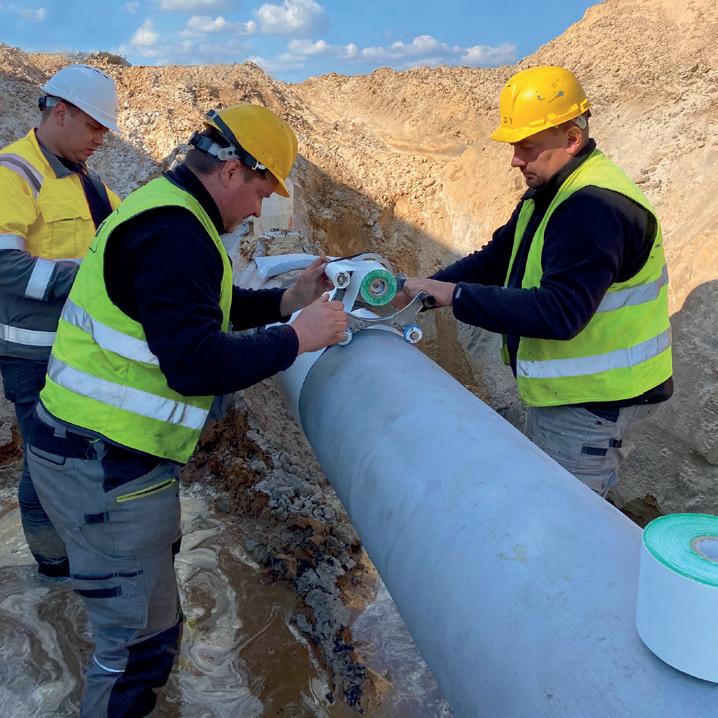
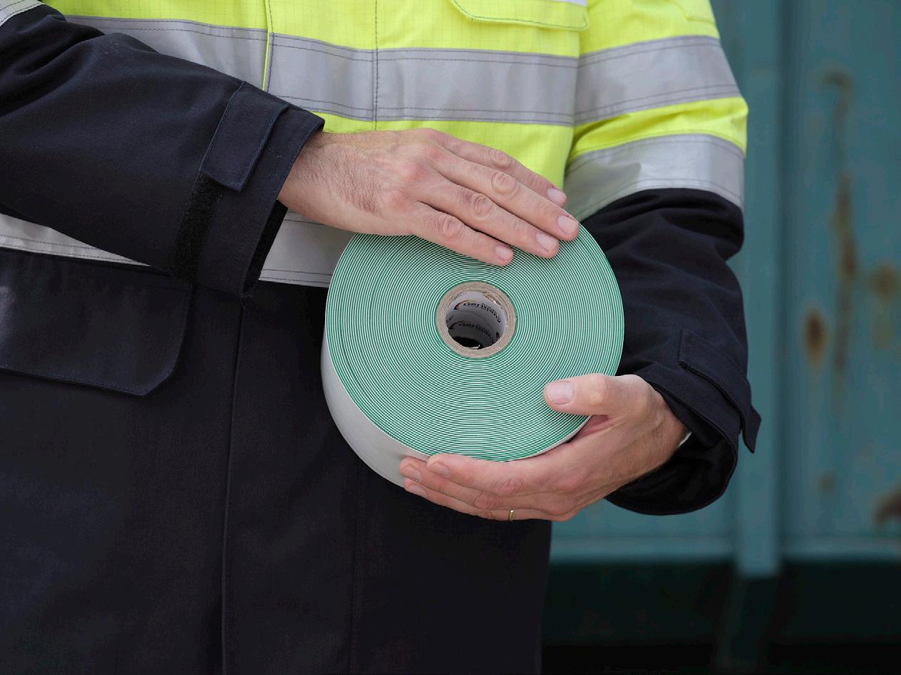
In modern pipeline construction, the requirements are clearly defined: shorter project durations, resource-efficient use of materials and energy, special protection for people and the environment and reduction of waste on the construction site. This poses increasing challenges for the industry. “In addition to permanent protection of pipe sections and weld seams, efficiency, safety and sustainability are particularly important. The necessary acceptance of all project participants can only be achieved through sustainable pipeline construction along the entire value chain, with a significant reduction in the CO2 footprint,” says Thomas Kaiser, Managing Director, DENSO Group Germany. Against this backdrop, DENSO developed an innovation in October 2021 that has radically simplified the protection of pipelines and weld seams ever since: SEALID combines reliable corrosion protection with strong mechanical protection in a single product. The innovative corrosion protection tape does not require a (solvent-based) primer and only needs to be wrapped around the pipe once. It therefore provides complete protection against corrosion and mechanical loads at the same time in a single step – without complex surface pre-treatment (e.g. sandblasting) or multi-step application processes. The leading international standards ISO 21809-3, EN 12068 and DIN 30672 are already met with a single wrapping process at operating temperatures up to +70°C (+158°F).
Comparison of currently available corrosion protection methods
In recent decades, six main methods have become established for passive corrosion protection for pipelines. They all offer
standardised and very good protection against corrosion and – often in combination with an additional product – also against mechanical stress. However, they differ in the type of application, the steps required, the number of products needed and the additional processing equipment required.
Petrolatum tape systems
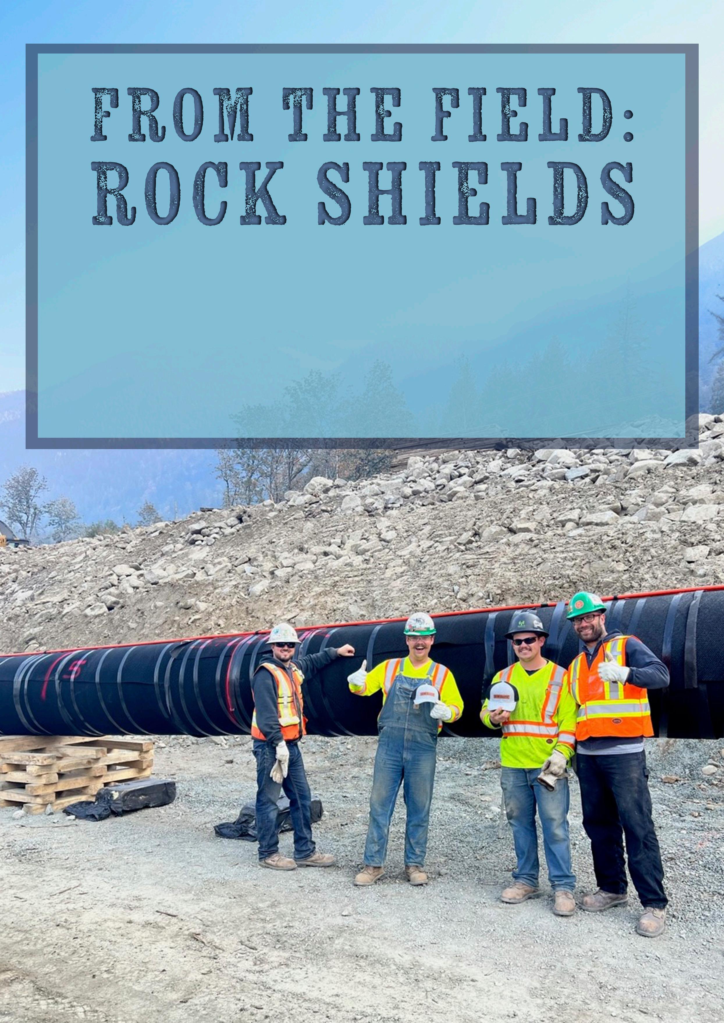
The flexible petrolatum tape, which is wrapped around the pipe with or without a primer, can follow certain movements of the pipeline in the ground without impairing its corrosion protection effect. However, its protection against mechanical loads is limited. For higher mechanical loads, an additional protective product must therefore be applied (e.g. a PE-, PVC-, PE/butyl-rubber-tape or another form of rock shield or similar).
tape systems (cold-applied)
tape systems (cold-applied)
rubber
systems (coldapplied)
sleeves (hotapplied)
applied)
Bitumen tape systems
Around 100 years ago, pipelines were coated with hot liquid bitumen. Today cold-applied bitumen tapes are still used, but in a combination of materials: they consist of a bitumen tape laminated onto a PVC or PE protective film, for example. Since the inner layer of this tape is made of bitumen and the outer layer of PVC or PE, the tape layers wrapped around the pipe cannot fully fuse together after application. There is a risk that cavities will form in the transition areas between the tape layers, where spiral corrosion can occur – a significant risk to the safety and longevity of a pipeline.
PE/butyl tape systems
Co-extruded 3-ply PE/butyl-rubber tapes feature a butyl rubber coating facing the steel pipe surface, a PE carrier film and a PE/butyl rubber outer coating in a single product. When wrapped around the pipe, a closed, hose-like coating is formed. The individual layers of the wrapped tape fuse together in a process known as self-amalgamation. The aforementioned problem of spiral corrosion does not occur. Although no additional product or device is required, the tapes often have to be wrapped around the pipe in several layers in at least two steps in order to meet the requirements of a high load class of international standards (e.g. ISO 21809-3
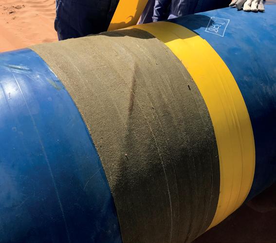
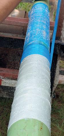
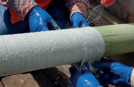
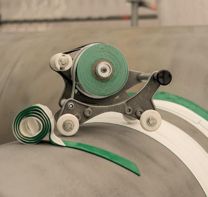
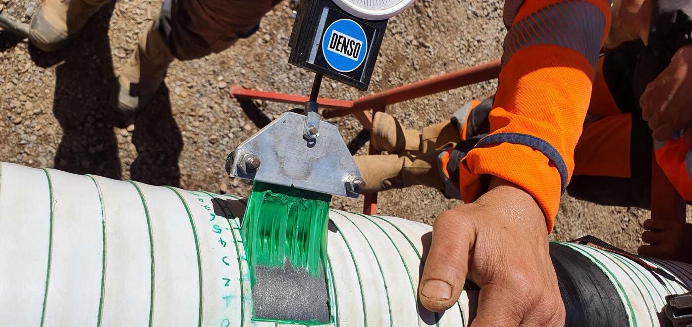
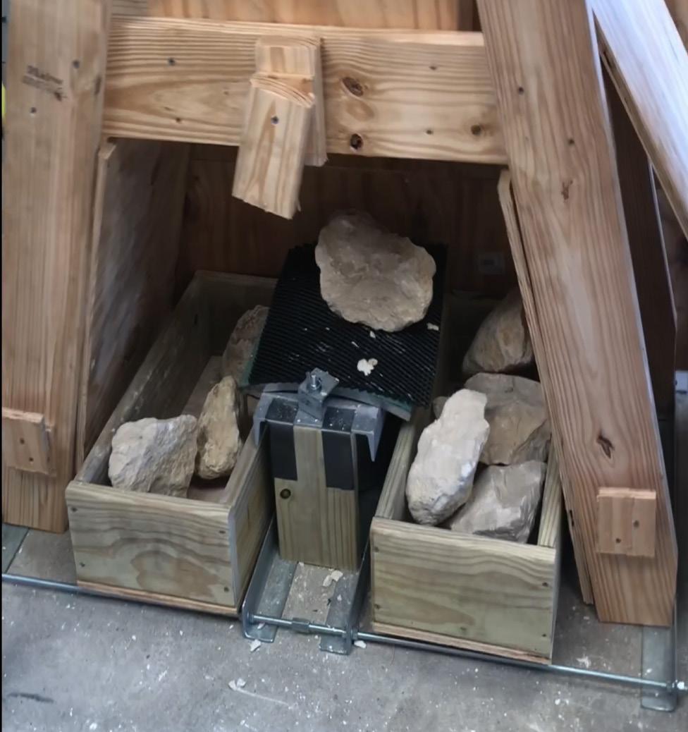
Figure 1. SEALID® in practical use with outstanding cohesive separation.
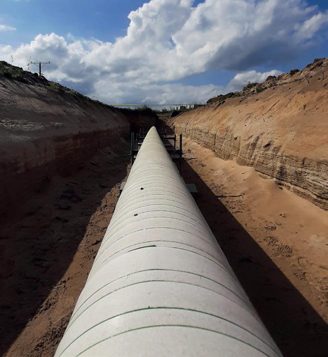
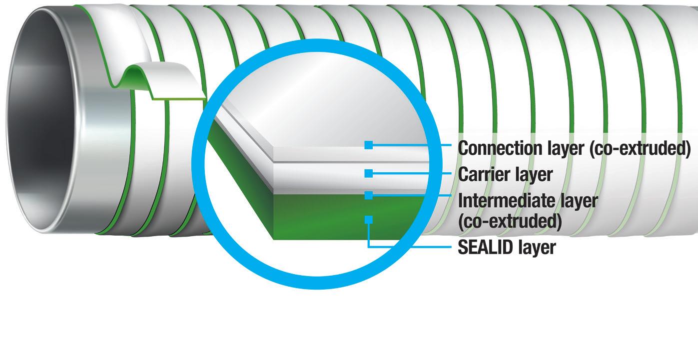
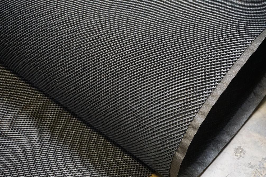
Figure 2. The innovative layers of the wrapped SEALID tape form a diffusion-tight protective sleeve with a long service life.
Table 1: Comparison of currently available corrosion protection methods
and EN 12068). In addition, a solvent-based primer is always necessary to increase the adhesion between the steel surface and the tape.
Heat shrinkable sleeves
Heat shrinkable sleeves in hotmelt or mastic versions are only suitable for protecting weld seams, but not for coating the entire pipe, T-pieces or pipe bends. After the steel surface has been preheated with a gas burner, which is often necessary, the shrink sleeve is applied to the weld seam, usually after applying a primer, and then shrunk using the gas burner. These systems are particularly sensitive to professional application (risk of airtrapping and overheating) and the cleanliness of the steel pipe surface. However, they offer a high level of corrosion protection and mechanical protection in a single product.
Liquid coatings
Brush- and spray-applied coatings based on epoxy or polyurethane (PU) require a very high degree of cleanliness of the steel surface. They are applied either manually with a brush or, more commonly, with compressordriven sprayers and also offer very good corrosion protection combined with high protection against mechanical loads. They are suitable for protecting weld seams as well as for coating entire pipes, T-pieces or pipe bends.
Viscoelastic tape systems
The flexible, viscoelastic corrosion protection tape is wrapped around the pipeline in a single step without the need for a primer or additional equipment. It offers very good protection against corrosion. However, as it is too ‘soft’ to provide the necessary protection against mechanical loads, an additional product is required: this is often a PVC or PE tape, but sometimes shrink sleeves are also used.
Beneficial product properties
SEALID is manufactured using genuine multi-layer co-extrusion and impresses with its properties. The layers of the tape wrapped around the pipe fuse together to form a diffusion-proof protective hose with exceptional durability and resistance. Impermeable to water vapour, oxygen, soil bacteria, and soil electrolytes, the protective hose achieves a minimised cathodic disbondment. Since SEALID is manufactured using genuine multi-layer co-extrusion, delamination of the individual tape layers is impossible. This ensures excellent peel and lap shear strength (Figure 1). The innovative solution can be used on pipelines at operating temperatures of up to +70°C (+158°F) and has also been confirmed as H2-ready.
It is extremely easy and quick to process. Rust removal from the steel surface with a brush is sufficient; no time-consuming sandblasting is necessary. Without preheating the surface
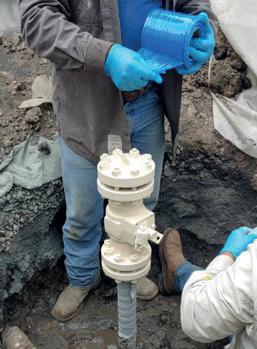
and without primer, the tape is wrapped around the pipe in a single step. No additional mechanical protection or other products are necessary. Whether for full pipe coating during rehabilitation, weld seam protection in new construction or protection of complex components, it acts as a universal solution for many areas of application. No hazardous substances, materials that are harmful to health or complex process engineering are used – a clear advantage for environmental and occupational safety (Figure 2).
A simple and environmentally friendly system
Compared to cold-processed tapes and tape systems, SEALID requires neither a primer nor a second tape for mechanical protection. Instead it is wrapped in a single step. This saves time, costs and materials and reduces waste on the construction site to a minimum. As no solvents are used, the impact on people and the environment is significantly reduced.
The complex sandblasting and preheating of the steel surface, as well as the time-consuming shrinking and rolling out of any air pockets, as required for heat shrinkable sleeves,
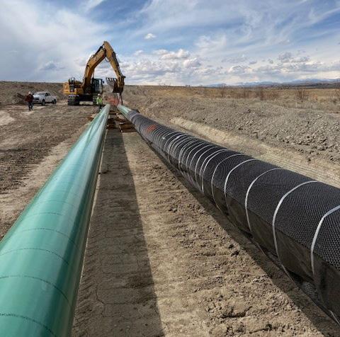
Figure 3. SEALID sets global standards for sustainable corrosion protection.
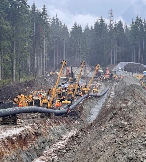
Figure 4. Environmentally friendly SEALID in a water protection area.
are eliminated. This prevents potential sources of error from the outset. SEALID can be applied in a single step – without additional equipment such as gas burners or complex protective measures. This significantly reduces time, costs and material consumption. While heat shrinkable sleeves are used almost exclusively on weld seams due to their design, it is also suitable for complete pipe sections, pipe bends and T-pieces thanks to its universal properties.
Unlike liquid brush-on and spray coatings, SEALID can be used regardless of external influences such as temperature or humidity. As no hazardous substances are used, no special protective equipment or devices are required – a plus for occupational safety and environmental protection. Preparatory measures such as sandblasting the surface are also not necessary. This significantly reduces time, material consumption and costs. Complex processing specifications, such as mixing ratios, layer thicknesses or curing times, are not required, which further simplifies application.
Unlike viscoelastic tape systems or petrolatum tapes, SEALID does not require any additional mechanical protection. A single product is sufficient to cover a wide temperature range of up to +70°C (+158°F). This not only significantly reduces material usage and costs, but also halves the processing time.
SEALID also improves occupational safety and environmental protection by avoiding the use of hazardous substances. In summary, there is a significant impact on reducing the CO2 footprint: when comparing the reduction in the CO2 footprint of SEALID with primerless viscoelastic systems, the CO2 footprint is reduced by 50% as no second product is required for mechanical protection. Compared to primer-based tape systems, the CO2 savings are even greater than 50% (Figure 3).
Use for new construction or rehabilitation
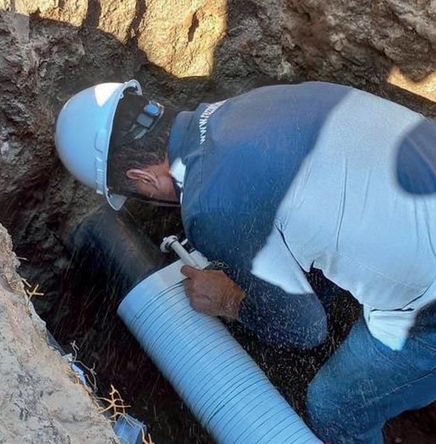
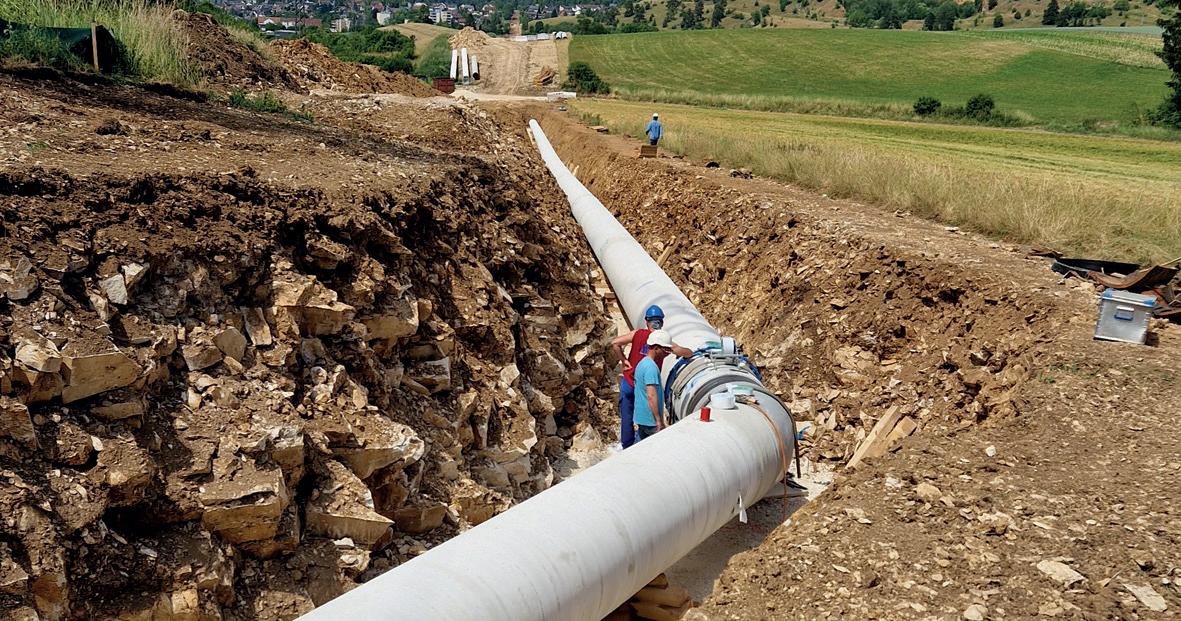
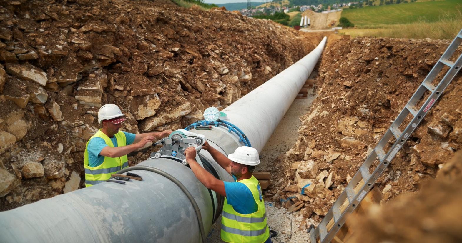
In water protection areas that serve to protect groundwater and drinking water supply for the population, particularly strict requirements apply to construction work on pipelines. Between 2022 and 2024, a cast iron pipeline that was over 100 years old and supplied drinking water to approximately 3 million people in southern Germany was replaced. The focus was not only on special environmental protection during the construction work; the materials used were also not allowed to endanger the ecosystem. The use of a primer was therefore strictly prohibited to protect the weld seams of the new pipe from corrosion. Thanks to its primerless application and low material consumption, SEALID All-in-1 was chosen as the solution. The patented product made a significant contribution to protecting nature and infrastructure in a safe and sustainable manner (Figure 4).
After intensive product testing, TERÉGA has also decided to approve SEALID All-in-1 as a corrosion protection solution. TERÉGA is one of two companies in France responsible for transporting natural gas via a 5000 km gas pipeline network. “As an operator of critical
infrastructure, the sustainable use of products and raw materials is very important to us. SEALID All-in-1 has met all our requirements. Unlike other corrosion protection solutions, no second product is required for mechanical protection. By using this system we are increasing the protection of workers and the environment on the construction site. What’s more, we can apply it faster and reduce the amount of waste”, says Damien Casteran, TERÉGA’s pipe and coating engineer. In 2025, DENSO Group Germany was awarded the contract for REVA, a local project within the TERÉGA network, to refurbish 1000 weld seams on an 8 in. pipeline. TERÉGA had already successfully implemented the All-in-1 solution in 2024: in addition to protecting weld seams, the contract also included the coating of 90° elbows and T-pieces for several new gas pipelines with diameters ranging from 3 - 24 in.
Cost efficiency and occupational health and safety aspects speak for themselves: the product has been approved in the specifications of a steadily growing number of oil and gas companies such as Shell Global Solutions International B.V. (Global), Ontras (Germany) and Gaz-System (Poland). A selection of further references from operators worldwide includes AB Amber Grid in Lithuania, rehabilitation of VilniusKaunas high-pressure gas pipeline, GAZ-SYSTEM in Poland, rehabilitation of gas pipeline in Poznań, SCGÁS in Brazil, rehabilitation of gas pipeline, NESTLÉ in France, rehabilitation of water pipeline and OMV Downstream GmbH in Austria, rehabilitation of gas pipeline.
Benefits of SEALID All-in-1
) No solvent-based primer, no substances harmful to humans or the environment.
) Only one step: wrap once – all done.
) Full protection against corrosion and mechanical loads in a single product.
) Complies with ISO 21809-3, EN 12068 and DIN 30672 (C50).
) H2-ready and operating temperature up to +70°C (+158°F).
) Universal solution for weld seams, full pipe wrapping, pipe bends, T-pieces, etc.
) Halves the CO2 footprint compared to primerless, viscoelastic corrosion protection systems.
) Fast and easy application, reduces material usage and thus construction site waste.
Conclusion
The SEALID technology revolutionises corrosion protection for weld seams and the complete rehabilitation of entire pipelines. In addition to the environmental benefits, protection for the user and significant reduction in CO2 footprint, the product’s ease of use and outstanding performance make it unique.
Corrosion protection in pipeline construction that is consistently designed for sustainability is not an additional expense, but a central measure for long-term CO2 footprint reduction. It combines technical integrity with resource efficiency, reduces repair and replacement costs and enables an economically and ecologically sustainable extension of service life. From a holistic perspective of infrastructure planning, it is therefore key to the climate-friendly transformation of the energy system.
Jennifer Knopf and Matthew Snape, Vink Chemicals, discuss how grotan® OX redefines microbiologically influenced corrosion (MIC) control in the oil and gas industry.
Pipelines are the arteries of the energy industry, but beneath their steady flow lies a silent threat: microbiologically influenced corrosion (MIC). Responsible for the majority of internal leaks, MIC costs operators billions in repairs, downtime, and lost product every year. Traditional defences – pigging and water-based biocides – offer only partial, short-lived protection. This article explores how biofilms fuel corrosion, why conventional solutions fall short, and how Vink Chemicals’ grotan® OX delivers a breakthrough in microbial and hydrogen sulfide (H2S) control, setting a new standard for pipeline integrity.
A silent enemy beneath the flow
Every drop of crude oil that travels through a pipeline carries not only energy value but also hidden risks. Among the most insidious of these risks is MIC, often described as corrosion with a living engine. Unlike mechanical abrasion or chemical degradation, MIC is powered by microorganisms, tiny yet destructive agents that quietly colonise steel surfaces, generating corrosive byproducts and leaving behind weakened infrastructure.
For decades, oil and gas operators have struggled with MIC. It is estimated that 70% of internal pipeline leaks are linked to this form of localised corrosion, with billions of dollars lost annually in repairs, downtime, and lost product. In a world demanding ever-higher standards of safety, efficiency, and sustainability, the industry cannot afford to fight MIC with outdated tools.
However, oil- and water-soluble biocide, grotan OX, is changing the rules of the game.
The
hidden mechanics of pipeline corrosion
The processing of crude oil is seldom as straightforward as it seems. Even after dehydration, residual water persists in emulsified form. As the crude flows, these droplets can gradually coalesce, accumulating at the ‘six o’clock position’ within the pipeline and forming small yet potentially hazardous pools of free water.
Each water droplet becomes a miniature bioreactor: enriched with sediments, scale minerals, hydrocarbons, and nutrients. Within these microenvironments, microbial communities thrive, forming dense biofilms. These biofilms are more than just surface slime, they are complex ecosystems where bacteria collaborate, feeding on carbon sources and producing corrosive byproducts like H2S.
Consequences are the formation of localised acidic pockets, which accelerate steel corrosion, promote iron sulfide (FeS) sludge deposition, and trigger a chain of operational challenges ranging from pipeline leaks to reduced refinery desalter efficiency.
The role of biofilms in MIC
Biofilms represent one of the most persistent and underestimated challenges in managing pipeline integrity. Far more complex than surface deposits, a biofilm is a structured microbial ecosystem encapsulated within an extracellular polymeric substance (EPS). This matrix is composed of polysaccharides, lipids, proteins, waxes, and mineral precipitates, giving it both physical durability and chemical resistance.
The EPS matrix acts as a dual-function shield. Mechanically, it anchors microbial colonies to pipe walls, resisting dislodgement during pigging operations. Chemically, it restricts the penetration of many water-soluble biocides, leaving the microbial ‘core’ largely unaffected by standard chemical treatments. Even high biocide concentrations often fail to reach the innermost layers, enabling microbial populations to survive and rebound quickly.
Within the biofilm, steep chemical gradients develop over very short distances. Aerobic zones near the surface can rapidly transition into anaerobic pockets deeper inside. These microenvironments foster the growth of specialised microorganisms such as sulfate-reducing bacteria (SRB), which thrive in oxygendepleted conditions and generate corrosive byproducts like hydrogen sulfide. The result is localised acidity, sulfide accumulation, and under-deposit corrosion, often manifesting as aggressive pitting.
Biofilms also enable microorganisms to communicate through quorum sensing, exchanging genetic material and coordinating defense mechanisms. This collective behaviour enhances resistance to chemical stressors, allowing microbial colonies to adapt rapidly to biocides and inhibitors. Moreover, fragments of the biofilm can detach, spreading resilient microbial communities downstream and seeding new colonies in other sections of the pipeline.
The persistence of biofilms contributes directly to:
) Accelerated pitting corrosion and steel degradation.
) FeS sludge buildup.
) Reduced efficiency of chemical treatments.
) Increased frequency of pigging operations.
) Long-term risks of pipeline leaks and refinery desalter fouling.
In short, biofilms transform microbial activity from a surfacelevel nuisance into a systemic integrity threat, demanding more advanced mitigation strategies than traditional mechanical and chemical approaches alone.
Why conventional solutions fall short
Traditionally, the industry has employed two strategies, often used in combination:
) Mechanical cleaning (pigging): removes scale, wax, and biofilm deposits.
) Chemical treatment: applies biocides, corrosion inhibitors, or scavengers to control microbial activity.
While effective to a degree, this approach suffers from limitations. Most conventional biocides are water-based formulations, which present two major drawbacks:
) They introduce additional water into export pipelines, inadvertently increasing the conditions for microbial activity.
) Their efficacy is restricted to bulk water phases, leaving emulsified droplets and interfacial zones under-treated.
The biofilm itself poses another challenge. Acting as a protective barrier made of polysaccharides, waxes, and minerals, it prevents many water-soluble biocides from penetrating to the microbial core. This means that despite regular dosing, microbial colonies often persist and re-establish themselves quickly after pigging operations. Clearly, the industry needs more than incremental improvements. It needs value innovation.
A new innovation
Vink Chemicals’ grotan OX is not just another pipeline additive, it is a breakthrough in biocide design tailored for crude oil systems. Unlike conventional products, grotan OX is almost water free and both oil- and water-soluble, a feature that completely changes its mode of action and operational impact.
Here’s why it stands out:
) Partitioning power: before water droplets even form in the crude, grotan OX disperses fully in the oil phase. As emulsified water coalesces into droplets, the biocide automatically partitions into them. This ensures that every droplet is treated at the microbial growth interface, suppressing biofilm formation at its very source.
) Effective at low dosage: with proven efficacy above 50 ppm, grotan OX delivers robust microbial control without excessive chemical loading.
) Dual-functionality: in addition to its biocidal effect, grotan OX acts as an H2S scavenger, irreversibly binding hydrogen sulfide and preventing sulfide-induced corrosion.
) Corrosion protection by design: with an alkaline pH and amine content, the product not only avoids the risks of acidic biocides but also contributes to stabilising pipeline pH and reducing corrosion rates.
In essence, it transforms each potential corrosion hotspot into a zone of protection.
Built for operational reliability
Field engineers know that a good chemical is more than just its lab data, it must deliver consistent performance
under real-world conditions. This solution was engineered with precisely this in mind, offering operators a suite of operational advantages:
) Non-foaming, non-emulsifying: even under turbulent pipeline conditions, it maintains flow integrity, preventing foaming and emulsion issues that complicate separation.
) Water-free formulation (<1%): unlike most biocides that contain 25 - 75% water, it adds no excess moisture to crude oil exports. This ensures compliance with export specifications and prevents unintended microbial growth stimulation.
) On-site measurability: residual concentrations can be measured quickly with a simple field test kit, enabling optimised dosage control and cost efficiency.
) Refinery benefits: by reducing FeS sludge formation, it alleviates downstream operational challenges, improving phase separation in desalters and reducing maintenance overheads.
Proven
technology, fresh applications
Though its application in crude oil pipelines may sound revolutionary, grotan OX is not untested. For decades, its baseline chemistry has been successfully applied in fuel treatment and storage, preserving diesel and kerosene against microbial spoilage. Its long-standing compliance with EN 590 diesel fuel standards and approval as an oilfield biocide (Yellow Banner, HOCNF) provide a robust foundation of safety, reliability, and regulatory acceptance.
This heritage allows operators to confidently extend the biocide into pipeline MIC control, combining trusted chemistry with new application insight.
Value innovation in action – looking ahead: a new standard for pipeline integrity
Value innovation means going beyond incremental improvements to deliver solutions that lower costs, boost effectiveness, and broaden applicability. The biocide exemplifies this by reducing chemical spend, extending asset life, simplifying operations, and supporting more sustainable chemical use.
The oil and gas sector is under mounting pressure to balance operational reliability, cost efficiency, and environmental responsibility. MIC remains a stubborn adversary, but with new innovations, the industry can finally take decisive steps forward.
MIC remains a constant threat, but industry approaches are evolving. A paradigm shift is delivered by combining multifunctional performance, corrosion inhibition, H2S scavenging, and water-phase efficacy, into one solution that reduces costs, simplifies operations, and supports sustainable pipeline integrity.
Imagine a future where every water droplet in a pipeline is pre-emptively neutralised as a microbial growth site. Where H2S formation is not just monitored but eliminated at the source. Where one chemical does the work of three, and integrity management becomes a proactive, sustainable practice rather than a reactive firefight.
That future is not hypothetical, it is already being realised wherever grotan OX is deployed.
Technical application case study
A well in a field in North Africa was selected for a field trial to evaluate the effectiveness of grotan OX for microbial and H2S control. The objective was to demonstrate biocide performance under real operating conditions by tracking changes in H2S concentrations and microbial populations in produced fluids. The trial was carried out over 45 h with continuous chemical injection through calibrated pumps.
Trial setup
Following mobilisation, the well was placed on the test separator for 24 h to establish baseline conditions. Samples were collected at multiple points: wellhead, well manifold, well riser, and test separator outlet. Baseline H2S, mercaptans, and microbial activity were recorded. Pump calibration was conducted with six piston-driven pumps, confirming an average delivery rate of 0.68 L/min – the maximum injection capacity available. The injection line was connected at the wellhead, and continuous dosing of grotan OX commenced. Tank levels were monitored against time to verify accuracy of injection rates.
Baseline conditions
Prior to treatment, H2S concentrations ranged from 325 - 362 ppm in crude oil samples, with mercaptans consistently above 330 ppm. Microbial activity in untreated produced water was high:
) SRB serial dilution: 105 CFU/mL after 5 - 6 days.
) ATP test: 51 pg/mL ATP, equating to approximately 104 microbial cells/mL.
These results confirmed a severe souring and microbial contamination problem requiring immediate mitigation.
Results
H2S reduction
Continuous injection of grotan OX at 0.68 L/min resulted in a marked reduction of H2S in produced fluids. Within 2 h at the wellhead manifold, H2S levels began to decrease significantly. At the test separator outlet, effective control was reached after approximately 8 h due to the presence of stagnant ‘dead oil’. This indicates that the chemical demonstrated rapid reactivity under multiphase wet-oil conditions and achieved broader system coverage with extended circulation.
Microbial control
Microbial monitoring showed significant improvement:
) SRB serial dilution (treated): counts stabilised at 103 CFU/mL (log 3) across six days – representing a two-log reduction compared to baseline.
) ATP (treated): levels dropped from 51 pg/mL to 0.1 pg/mL, indicating near-complete elimination of planktonic microbial activity.
The combined results confirm that it was highly effective against both SRB and total microbial populations.
Discussion
The trial validated the strong dual functionality of grotan OX as a biocide and H2S scavenger. Its performance was noteworthy given the limited contact time in well fluids and complex multiphase conditions. H2S reduction occurred quickly at the wellhead, while microbial suppression was sustained over the trial duration, indicating prolonged efficacy. The delay in test separator H2S response was attributed to residual untreated fluids rather than biocide performance.
Key learnings include the importance of:
) Ensuring maximum pump capacity to achieve effective chemical dosage.
) Monitoring across multiple sampling points to account for system lag times.
) Combining chemical analysis with microbial surveillance for holistic treatment validation.
Conclusion
The field trial demonstrated that grotan OX is an effective solution for controlling H2S and microbial activity in oilfield production systems. Continuous dosing achieved rapid H2S scavenging and significant microbial load reduction, even under challenging conditions. These results support its application as part of a long-term souring and microbial management strategy in comparable fields.
Table 1: SRB serial dilution test: baseline vs after treatment
Table 2: ATP test:
Jamie Carter Clark, Grid-Guard, USA, examines how next-generation rock shields combine durability, flexibility, and cathodic protection for long-term pipeline performance.
Rock shields have been used with increasing frequency over the last several decades because of the recognised threat of damage to pipeline coatings and the growing philosophy of ‘better safe than sorry’. Since corrosion remains the greatest threat to buried pipeline systems, combining a rock shield with a cathodic protection system helps extend the life of the coatings that protect our pipelines.
Originally, the primary purpose of a rock shield was to ensure that coatings were not damaged during backfill operations. Over time, more and more pipeline owners have chosen to use rock shields on their lines. Some combine it
Figure 1. Happy labour hands on project in southern B.C., Canada
with sand padding, others used it alone as an engineered layer of protection, designed to guard against abrasion and impact from falling rock. The second, equally important, purpose of a rock shield is to continue that protection after burial without becoming the cause of coating damage or creating potential holidays.
In this article, we’ll cover the differences that make Grid-GuardHD PLUS the choice of engineers and contractors alike. You’ll see that it was designed not only to withstand the harsh conditions of backfill operations but also to continue protecting the pipeline coating long after burial.
Rock shields, a history
For the past few decades, stranded rock shields made of PVC have dominated the market. Originally developed for another purpose, they were eventually adapted to protect pipeline coatings in rocky terrain. Early on, only a single manufacturer offered these products. Today, the market includes several
options of rock shield, each with its own material characteristics, advantages, and shortcomings.
Rock shields in today’s market
The most commonly used rock shield, both historically and today, is made from PVC strands manufactured in a spaghetti-like pattern. This type of shield derives its strength primarily from thickness, which can also make it heavy, costly, and cumbersome to handle in the field. Because of the way the strands are stacked, the shield is difficult to manage in cradles during lowering-in operations and often tends to bunch or tear. This issue, in combination with weight, roll dimensions, man-power requirements, and cost, creates a barrier for growth.
One of the newer alternatives on the market is a thick geotextile rock shield. Like the stranded PVC versions, it also relies on thickness for strength. However, this design introduces additional challenges. It is heavy, can be awkward to install, is prone to retain water during rainy weather, and can freeze in cold temperatures: conditions that make installation slow, difficult, and potentially hazardous. These factors, combined with the high cost of manufacturing, can make it one of the most expensive rock shield options.
Choosing a rock shield
Grid-GuardHD PLUS was designed and engineered after years of collaboration with pipeline design engineers, corrosion specialists, integrity management teams, and field contractors. Every feature of the product was developed to address their most common concerns, combining durability, flexibility, and ease of use. The following section will address each of these concerns.
Impact resistance
Grid-GuardHD PLUS outperforms most rock shields on the market in impact resistance, successfully absorbing impact from rocks up to 8 in. in diameter dropped from a height of 6 ft. Grid-GuardHD Plus gains its strength from a consistent bi-directional polyethylene grid, reinforced by a heat-welded 6 oz geotextile backing. This combination of layering and material design dramatically increases impact resistance and minimises coating damage.
Our third-party testing partner has developed and maintains a specialised rock-drop testing device to simulate real-world installation conditions. Large and small rocks are dropped multiple times onto an FBE-coated steel plate with Grid-GuardHD PLUS attached. To pass the test, the coating must remain completely free of holidays after three consecutive drops, ensuring that the shield truly performs in the field, as well as in theory. Grid-GuardHD PLUS provided passing results with every test.
Void space and surface protection
Traditional rock shields feature open apertures that allow for cathodic protection current to flow consistently. However, these open areas leave portions of the coating exposed to potential threats. Small fragments of rock or
Figure 3. Rock-drop test.
Figure 2. Image courtesy of Cross Country Canada.
debris can become trapped in the openings, scouring, or abrading the coating over time.
Grid-GuardHD PLUS is the only rock shield that combines the strength of a structured polymer grid with the protection of a permeable geotextile layer, effectively eliminating open apertures. This dual-layer approach provides complete surface protection while still allowing moisture and cathodic current to flow freely around the pipe.
Cathodic protection performance
Most rock shields on the market do not inhibit cathodic protection, but few can claim to enhance it. Grid-GuardHD PLUS does both. It protects the coating while actively supporting cathodic protection flow. The lightweight 6 oz geotextile backing allows fines to make limited contact with the coating surface while still enabling water and cathodic current to circulate naturally around the pipeline without obstruction. The result is a balanced environment that maintains corrosion protection while ensuring mechanical durability.
Cold-weather flexibility
Grid-GuardHD PLUS was specifically designed with coldweather flexibility in mind. It remains pliable and easy to handle even in temperatures as low as -40˚F. During field testing, the product consistently maintained flexibility without cracking or stiffening. This eliminates the need for pre-heating or special handling procedures before installation, saving valuable time in cold climates and ensuring reliable performance year-round.
Field installation
Historically, rock shield installation has been a tedious, labour-intensive process. Many traditional materials are heavy, difficult to position, and prone to shifting during lowering-in. Grid-GuardHD PLUS was developed to simplify that process. It is lightweight yet maintains enough rigidity to hold its shape, allowing a single worker to carry and position it easily. The material requires less tape for secure installation, and its smooth geotextile backing allows cradles to slide cleanly over the pipe without bunching or tearing. These improvements reduce installation time and labour costs while improving safety and consistency in the field.
Sizes and configuration
Grid-GuardHD PLUS is manufactured in widths precisely matched to common pipeline diameters, ensuring an ideal fit and consistent coverage. Grid-GuardHD PLUS is available in pads (width x 6 ft) or rolls (width x 50 ft), both of which can be easily cut to size in the field. Because of its lightweight construction, it wraps smoothly around both small and large diameter lines and drapes naturally for a snug fit.
Storage and weather resistance
Grid-GuardHD PLUS is built for longevity and field resilience. It is made with carbon black which includes a full year of built-in UV protection, along with an additional year
of UV resistance from the protective film used for shipping and storage. Unlike textile-based rock shields that can retain water, Grid-GuardHD PLUS does not absorb moisture and can be stored or installed in wet conditions without risk of deterioration, mold, or freezing. This makes it an excellent choice for projects in humid or variable climates.
Overall cost efficiency
Despite being the highest-quality rock shield available, Grid-GuardHD PLUS is also among the most economical to ship and install. Its low weight reduces freight costs, and its easy handling cuts down on labour time during installation. The engineered draping behaviour requires less tape and rework, further improving efficiency. Over the life of a project, these combined advantages translate into measurable savings for both the owner and the contractor.
Figure 4. Grid-GuardHD PLUS extruded poly with geotextile backing.
Figure 5. Grid-GuardHD PLUS in cradles B.C., Canada.
How it is made
Grid-GuardHD PLUS is manufactured using a proprietary polyethylene (PE) formulation that produces a crush-resistant, yet highly flexible, core – ideal for installation in challenging terrain and cold weather. The formula also incorporates 20% recycled polymer, supporting sustainability without compromising quality or performance.
The polymer grid is permanently laminated to a non-woven cushioning geotextile through a precision heat-welding process. This method not only ensures strong adhesion between layers but also enhances the overall tensile and impact properties of the finished product. The result is a rock shield with superior structural integrity, durability, and performance consistency under stress.
Feedback from the field
) During a recent project that required cradle usage on a large diameter line, the Superintendent was pleasantly surprised to realise he could easily manoeuvre the cradles over Grid-GuardHD PLUS while lowering in. “In my 36 years of pipeline work, Grid-GuardHD PLUS is hands-down the best and easiest rock shield I’ve used. It’s incredibly lightweight, manageable, and simple to install, with no issues during backfill or when using cradles during lowering-in. Unlike other brands that are heavy, awkward, and difficult to work with in winter conditions, Grid-Guard stands out as a reliable, user-friendly solution. As long as it’s client-approved, I’ll be using it on every project moving forward.”
) During a buried test of Grid-GuardHD PLUS alongside a traditional rock shield with the gas company in attendance, a large rock approximately 12 in. in diameter fell from the top of the dirt pile and rolled directly across the rock shield on the exposed part of the line. The result was a failure of the traditional rock shield and the immediate approval of Grid-GuardHD PLUS. “What makes this rock shield unique is the fact that it incorporates a felt-like material on the side that contacts the pipe. This allows the shield to slip smoothly on the coating, reducing soil stress that might otherwise cause the shield to dig into the tape, leading to wrinkles or holidays”, said Jim Wynn, corrosion specialist.
) Since 2023, a contractor has used only Grid-GuardHD PLUS on the lines he is responsible for. During his most recent project, he remarked on his years of construction experience and the ease of use with Grid-GuardHD PLUS, when compared to other rock shields: “I’ve been in pipeline construction for over 30 years and wish this product had been available sooner. It’s so much easier to use: super flexible, easy to tape, and far less hassle in the field. I’m sold.”
) During a recent presentation of the product’s benefits, an engineering group was particularly interested in the benefits of using it alongside cathodic protection: “Grid-GuardHD PLUS provides not only the impact protection we need but also the ability to maintain that protection long after burial. A great and much-needed innovation for our industry.”
Conclusion
Grid-GuardHD PLUS represents an evolution in rock shield technology. Designed for performance, engineered for reliability, and proven through extensive testing, it delivers superior protection during installation and continues to safeguard the pipeline long after it’s buried.
Figure 6. Grid-GuardHD PLUS on line in Utah, USA.
Figure 7. Image courtesy of Cross Country Canada.
Atanu Dutta (UK), Pardeep Kumar Kaundal, Sangram Biswal, Abhineet Gupta, Nilesh Patil, and Ashish Negi, Oceaneering, India, discuss how modular, field-ready systems designed for resilience, efficiency, and environmental responsibility could serve as a leap forward in emergency pipeline repair.
In the intricate web of global infrastructure, pipelines stand as indispensable arteries, silently facilitating the colossal movement of hydrocarbons, water, and other critical resources across vast and varied terrains. Their continuous and secure operation is not merely an operational need but a foundational pillar for global economic stability, environmental protection, and public safety. The integrity of these extensive networks, however, is perpetually challenged by an array of dynamic threats, ranging from the unpredictable forces of nature and geological instability, to the complexities of operational wear and the potential for external interference. When an unforeseen incident compromises pipeline integrity, the repercussions can be profound, manifesting as significant financial liabilities, severe environmental degradation, and potential risks to human life and community well-being. It is within this critical context that the strategic importance of robust and rapidly deployable emergency pipeline repair systems (EPRS) becomes clear.
From contingency to comprehensive resilience Historically, pipeline incident response relies on reactive, ad-hoc measures, leading to prolonged downtime and amplified consequences. The evolution of the pipeline industry, driven by heightened regulatory scrutiny, technological advancements, and an increasing emphasis on corporate social responsibility has transformed the approach to pipeline integrity management. EPRS are more than mere contingency plans. Today, they represent highly sophisticated, meticulously engineered, and pre-positioned solutions specifically designed to minimise
operational disruption, drastically mitigate environmental impact, and restore pipeline functionality with unparalleled speed and efficiency. These systems encompass a comprehensive suite of tools, techniques, and trained personnel, capable of addressing a diverse spectrum of damage scenarios, from minor leaks to catastrophic ruptures, in both onshore and challenging offshore environments.
In an era defined by escalating energy demands, stringent environmental standards, and an imperative for operational excellence, the continuous advancement and strategic deployment of EPRS technologies and methodologies are vital for ensuring the enduring resilience and reliability of the world’s critical pipeline infrastructure.
To meet these new requirements, Oceaneering sought to develop a new, patented, seal assembly for pipeline spool pieces to eliminate welding during subsea repairs. This solution reflects a shift in industry priorities, from reactive repairs to pre-engineered and easily deployable solutions. As safety standards, environmental regulations, and operational expectations continue to rise, this kind of innovation is redefining how we manage pipeline reliability under challenging conditions.
Pipeline spool piece seal assembly
The patented pipeline spool piece seal assembly (US Patent No. 12140260-B2) provides a strong mechanical seal by placing an engineered sealing member between a controlled surface EPRS and an irregular or damaged pipeline surface. Hydraulic or mechanical actuators compress the seal, creating a secure barrier even on rough or mill-finished pipes surfaces.
This design is modular, scalable, and suitable for pipelines up to 48 in. in diameter. It’s also capable of handling pressures exceeding 10 000 psi, making it ideal for demanding subsea applications. Unlike traditional elastomeric seals, this system maintains its integrity across extreme temperature variations and repeated pressure cycles, resisting common failure modes such as compression set, thermal degradation, and rapid gas decompression. The spool piece itself is designed to integrate seamlessly into existing pipeline systems and can be installed quickly with minimal surface preparation.
Applications and benefits
The primary application of this technology is in the upstream and midstream oil and gas industry, particularly for subsea pipelines that are difficult or dangerous to access. However, its versatility extends to other high-risk or remote infrastructure environments, such as topside offshore platforms, nuclear facilities, petrochemical refineries, and hydrogen transport pipelines.
The benefits are considerable. First, the system significantly reduces repair time, minimising operational downtime and associated financial losses. Second, it eliminates the need for hyperbaric welding, thereby enhancing personnel safety and reducing deployment costs. Third, it provides a more reliable seal under variable operating conditions, improving long-term asset integrity. Finally, its modular design means it can be adapted to a range of pipe diameters and surface conditions without extensive customisation, which greatly simplifies logistics and inventory management for operators.
Case studies
During initial field trials, the seal assembly was pressure-tested on a 12 in. pipe segment. To simulate realistic subsea conditions, a mill-finished pipe was used. The assembly was tested up to API 10K class, i.e. 10 000 psi, with no leakage observed, demonstrating the seal’s effectiveness against field pipe surfaces.
A distinct sealing region was observed after the test, indicating strong engagement between the seal and the pipe surface. This demonstrates the seal assembly’s ability to achieve a reliable high-pressure seal against the pipe’s natural roughness, maintaining sealing integrity even under pressure cycling. When considered in conjunction with the rapid installation times, these results validate the robustness and practical value of the design.
The challenge
Subsea pipelines, critical to the oil and gas industry, frequently suffer from structural damage that necessitates the removal and repair of defective segments. Historically, hyperbaric welding has been the go-to method for such repairs. However,
Figure 1. Left: sealing region of the first seal shows how it engages the mill-finished pipe’s roughness to generate a high-pressure seal. Right: sealing region of the third seal shows two distinct sealing locations that act against the mill pipe’s roughness to form a high-pressure seal.
there are downsides to the technique, including the health and safety risks posed to personnel, and increased project costs.
Limitations of existing techniques
Current repair methods often rely on elastomeric seals, which, despite their ability to accommodate mill-finished pipe surfaces, exhibit several limitations under fluctuating temperatures:
) Limited resistance to high and low temperatures.
) Compression set.
) Degradation due to thermal and pressure cycling.
) Rapid gas decompression.
) Ageing.
The innovative solution
The new patented spool piece seal assembly solution introduces a sophisticated seal assembly integrated into a pipeline spool piece, specifically engineered to address the shortcomings of traditional repair methods. This innovative system is distinguished by its high performance, as it operates reliably under extreme pressure and temperature conditions, including those found in subsea environments. Its modular design ensures adaptability and facilitates quick, dependable installation, while its versatility allows it to function effectively on damaged or irregular pipe surfaces and accommodate large diameter pipelines up to 48 in. Additionally, the solution promotes efficiency by enabling rapid deployment and restoring pipeline integrity without the need for extensive
EPISODE TEN
Featuring Alexandra Kostereva, Operations Manager at GERG (European Gas Research Group). In this episode, we learn about the role of GERG in European gas pipeline innovation, research, and decarbonisation strategy. Tune in to hear more about:
• The most pressing technical challenges currently facing gas pipelines in Europe.
• What kind of innovations or adaptations are being explored for existing pipeline infrastructure.
• How GERG ensures that pipeline-related research translates into real-world safety, sustainability, or efficiency improvements across the continent.
• Energy resilience in Europe.
Listen and subscribe here
Figure 3. Second seal design illustrates the twist-to-seal principle on pipe’s outer diameter.
Figure 2. First seal design illustrates how it bends to seal on the pipe’s outer diameter.
