
International Research Journal of Engineering and Technology (IRJET) e-ISSN: 2395-0056
Volume: 12 Issue: 02 | Feb 2025 www.irjet.net p-ISSN: 2395-0072


International Research Journal of Engineering and Technology (IRJET) e-ISSN: 2395-0056
Volume: 12 Issue: 02 | Feb 2025 www.irjet.net p-ISSN: 2395-0072
Assistant Professor Department of Civil Engineering, D. Y. Patil International University, Maharashtra, India
Assistant Professor Department of Civil Engineering, D. Y. Patil International University, Maharashtra, India
Abstract - India is fastest growing anddeveloping county in infrastructure and all other sector. Infrastructure development is major factor of any county, but for infrastructuredevelopmentnecessitiesoflandismajorfactor. Due to rapid urbanization there is less availability of land in plain area hence utilization of land in mountain area and sloping area become mandatory. But land in mountainous area is become major problem in construction hence special analysis andcare shouldbe taken while constructing projects in this area. In this project we have considered different floor steel structure like G+10 and G+20 and done analysis with different sloping ground varying from 0, 5, 10 degree. For above structure analysis is done for story displacement
Key Words: STAAD.Pro,SlopingBuilding,Stepback,Bracing system,HighriseBuilding
Due to increase in population and rapid urbanization, the scarcity of plain ground is happened. Since structures are constructedinhillyarea.Theconstructionofbuildinginhilly area is not easy compared to building in plain ground. In some hilly regions of the world are more pronto seismic activity,InIndia,Northandnortheastparthavelargesloping grounds and construction of RC building is popular in sloping ground. Earthquake causes shaking of ground so buildingrestingonslopewillexperiencemotionatitsbase. Even though the base of the building moves with ground. Roofhastendencytostayinoriginalposition.Butsincethe walls and columns are connected toit, they drag the roof alongwiththem.Earthquakesarethenaturalphenomenon whicharecausedbythereleaseoflargestrainenergybythe moving faults below the surface of the earth, which ultimatelycausestheshakingoftheearthtopsurfaceinall possibledirectionswithdifferentamplitudesandintensities oflateralforces.
Ashraf. (1998)
Ashrafetal.(1998)presentsthestepsusedinperforminga pushover analysis of a simple three-dimensional building. SAP2000, a state-of the-art, general purpose, threedimensionalstructuralanalysisprogram,isusedasatoolfor performing the pushover. It allows quick and easy implementationofthepushoverproceduresdescribedinthe ATC-40andFEMA-273documentsforbothtwoandthreedimensional buildings. He suggested that it is easy to
investigatetheerectofdifferentstrengtheningschemesand also to stiffen or strengthen the building by changing the memberpropertiesandrerunningtheanalysis.
Armagan Korkamaz et al. evaluated the performance of frame structures for various load patterns and variety of natural periods by performing pushover and non-linear dynamictimehistoryanalysis.Pushoverandnon-lineartime history analyses results are compared to choose the best loaddistributionforspecificnaturalperiodforthistypeof framestructure.Theyconcludedthattheshearfailureofthe columnsisexperiencedatthelargerstoreydisplacements and rectangular distribution always give the higher base shear-weightratiocomparingtootherloaddistributionsfor thecorrespondingstorydisplacement.Therectangularload distributionshowsmaximumseismicdemandsduringthe given earthquakes more reasonable than the other load distribution
A.Meher Prasad
A.Meher Prasad et al. (2004) studied the effect of infill stiffnessonseismicperformanceofmulti-storeyRCframed buildingsinIndia.Twotypicalexistingbuildingslocatedin moderateseismiczonesofIndia(asperIS:1893-2002[1]) are identified. Features like plan irregularity and vertical irregularity(softstorey)arefoundinoneofthebuildings, while the other is fairly symmetric. Infill’s were modelled using the equivalent strut approach. Static analysis (for gravityandlateralloads),responsespectrumanalysisand non-linearpushoveranalysiswerePerformed.Itisobserved that the seismic demand at the soft storey level is significantly large when infill stiffness is considered, with largerbaseshearandlargerdisplacements.
A.Fiore et al. (2012) studied about the inuence of infilll panels over the collapse mechanisms activated under pushoveranalysis.alargenumberofresearchstudieshave been recently devoted to the modelling and analysis of inflledRCframedbuildingsunderseismicactions,andthe significantrolethattheinfillplaysintheoverallstructural performance is by now a well acknowledged result. In particular, the extension of N2 method to infilled frame allows the appraisal of this contribution within the frameworkofanonlinearstaticanalysis.Numericalanalyses wereperformedbyusingspatialmodels,bothforthebare framesandinfilledframes,inordertoappraisethevariation

International Research Journal of Engineering and Technology (IRJET) e-ISSN: 2395-0056
Volume: 12 Issue: 02 | Feb 2025 www.irjet.net p-ISSN: 2395-0072
of the structural capacity because of the interaction of theinfillswiththeRCelements.
Anoop Singh , Vikas Srivastava , N.N.Harry
Anoop Singh , Vikas Srivastava , N.N.Harry has concluded that The displacement of beam coming in the building is withinthelimitsofIndianstandards.Thisbuildingissafefor areacomingunderearthquakezoneII.Themaximumdriftin thebuildingis2.077cmwhichissafeasperIS1893-2002. Themaximdriftinthebuildingis2.077cmwhichissafeas perIS1893-2002.Themaximumbeamdisplacementof3m span beam is 0.044mm and allowable displacement is 12mm.
Sachin Kumar Dangi , and Saleem Akhtar
SachinKumarDangi,andSaleemAkhtarhadsaidthereis significantimprovementobservedinseismicperformanceof building on sloping ground by providing shear walls with different configurations since lateral displacement and member forces reduce considerably in building due to provision of shear walls. It is observed that maximum displacementisfoundincaseof45slopewithoutshearwall. Hencewecansaythat,riskincreaseswiththeinclinationof the slope. In this study we found that, the position of the shear wall at periphery is the optimum position for the lateralloadresistance.Itisobservedthat,thepositionofthe shearwallatcorneristheoptimumpositionforcountering axial loads. It is observed that, maximum shear force and maximumbendingmomentincreasesignificantlyforsloping groundat45slope.Itisobservedthat,axialforceincreases in the buildings with shear wall. Base shear is found maximuminthebuildingwithshearwall,duetodeadloadof theshearwall.
B.G. Birajdar , S.S. Nalawade
B.G. Birajdar , S.S. Nalawade has said The performance of STEP back building during seismic excitation could prove morevulnerablethanotherconfigurationsofbuildings.The developmentoftorsionalmomentsinStepbackbuildingsis higherthanthatintheStepbackSetbackbuildings.Hence, StepbackSetbackbuildingsarefoundtobelessvulnerable thanStepbackbuildingagainstseismicgroundmotion.In Stepback buildingsandStepback-Set back buildings,it is observedthatextremeleftcolumnatgroundlevel,whichare short, are the worst accepted. Special attention should be giventothesecolumnsindesignanddetailing.Although,the Setbackbuildingsonplaingroundattractlessactionforces as compared to Step back Setback buildings, overall economiccostinvolvedinlevelingtheslopinggroundand otherrelatedissuesneedstobestudiedindetail.
Various research paper compared the buildings with different seismic zones, with different climatic conditions, different land profiles but there is very less research regarding effect of slopes on the building with varying
seismiczones.InthisprojectwehavecomparedaBuilding fordifferentslopeslike0,10,20,30degreeslopeandvary seismiczoneslikesI,V.
Theobjectiveofthisprojectisastudyoftheeffectofslopes ona buildingin byusingdifferentbracingsystem .Inthis project, we are going to analyze multistory building in varying slopes by using software like STAAD. Pro. In this project, we are going to structurally compare the G+10 , G+20 story building with various slopes like 0, 5, 10, , degreeandwithdifferentseismicconditionslikeZoneIand ZoneV.Andattheendwewillfindsomeresults.Theresults include
4 Building Configurations
1. PlanDimension20mx24m
2. StoryHeight3.2m
3. Numberofstories i) InG+10=11stories ii) InG+20=21stories
ThefollowingWindLoadparametersweretakenasperIS 875(Part3):
WindSpeed,Vb(m/s) 47
Terraincategory 3
Structureclass C
RiskCoefficient(k1factor)1
Topography(k3factor)1
4.1 Lateral Load Parameters
ThefollowingEarthquakeLoadParametersweretakenas perIS1893:2002:
Responsereductionfactor(R) 5
Seismic zone- III
Seismiczonefactor(Z)0.16
Soiltype-II
Importancefactor -1
TimeperiodProgramcalculated
4.2 Load Definitions
Thefollowingloadhasbeenconsideredtobeactingon boththestructures:
Deadload:weightofthestructure.
Superimposedloadduetofinishingetc.:2kN/m2
LiveLoad:3.5kN/m2
EarthquakeinX-directionAsperIS1893:2002
EarthquakeinY-direction:AsperIS1893:2002
Windload:AsperIS875(Part3)
4.3 Frame sections
Column–Isection–I100016B55020
Beam-Isection–I80016B50012
ChannelSection -ISA125
SlabThickness -120mm

International Research Journal of Engineering and Technology (IRJET) e-ISSN: 2395-0056
Volume: 12 Issue: 02 | Feb 2025 www.irjet.net p-ISSN: 2395-0072
ResponseSpectrumanalysisforseismicloadingwhilelinear staticanalysisforwindloadinghasbeencarriedoutforall the structures using STAAD.Pro and the results are representedinthefollowingform:
Storydisplacement
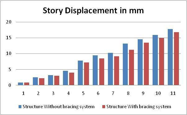
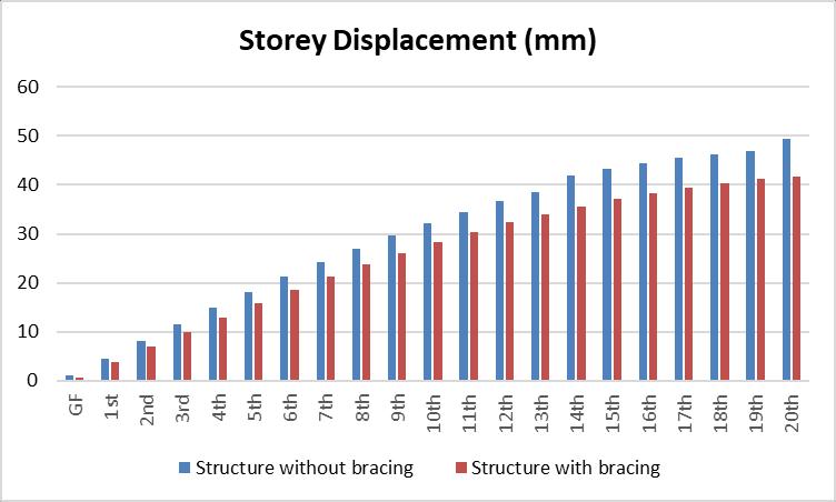
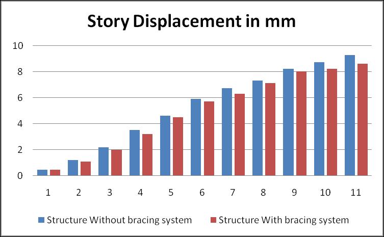
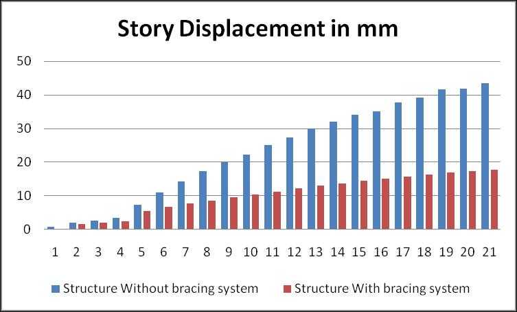
Comparativestudybetweenabuildingonslopinggrounds withsomeslopewithdifferentbracingsystem.Inthisreport structure is considered with and without any slope G+10,G+20 and analyses is done Tabulated result and graphsareas below
STORY DISPLACEMENT (mm) Story
Table-2–G+20buildingwithoutanyslope
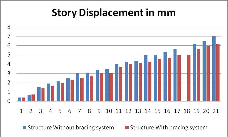
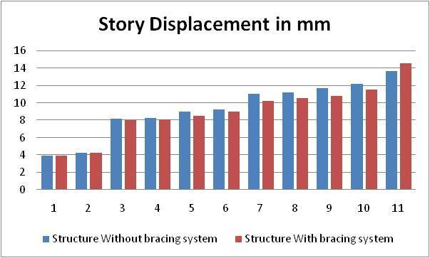
Table-1–G+10buildingwithoutanyslope STORY
DISPLACEMENT (mm)
Table-3–G+10buildingwith5degreeslope

International Research Journal of Engineering and Technology (IRJET) e-ISSN: 2395-0056
Volume: 12 Issue: 02 | Feb 2025 www.irjet.net p-ISSN: 2395-0072
STORY DISPLACEMENT (mm)
Table-4–G+20buildingwith5degreeslope
STORY DISPLACEMENT (mm)
Table-5–G+10buildingwith10degreeslope
STORY DISPLACEMENT (mm)

International Research Journal of Engineering and Technology (IRJET) e-ISSN: 2395-0056
Volume: 12 Issue: 02 | Feb 2025 www.irjet.net p-ISSN: 2395-0072
Table-15–G+20buildingwith10degreeslope
Following conclusion observed after analysis of different G+10,G+20,,structurewithdifferentslopingangleas0,5, and10degree.Resultsarecomparedforstorydisplacement Forstructurewithandwithoutdifferentbracingsystem.
1.Forstorydisplacement
a. Considering G+10 building results are compared which shows that, Building with out bracing without for same loadingandsamesectionproperty.Ithasbeenobservedthat storydisplacementisincreasedwithheightofthebuilding and which is varying from 3.95 mm to 14.5 mm. Same observation made building with bracing that story displacementisdecreased withheight ofthe building and whichisintherangeof 3.95 mmto12.2 mm exceptfor zero degree slope. Overall improvement in story displacementwhichisaround5to6% lessforbuildingwith bracing.Henceresultsshowthatstorydisplacementsinthe structurereducedwhenstructureisprovidedwithbracing.
b. Considering G+20 building results are compared which shows that, Building without bracing without for same loadingandsamesectionproperty.Ithasbeenobservedthat storydisplacementisincreasedwithheightofthebuilding and which is varying from 4 mm to 69 mm. Same observation made building with bracing that story displacementisdecreased withheightofthebuildingand whichisintherangeof4to62mm exceptforthirtydegree slope.Overallimprovementinstorydisplacementwhichis around 20 %less for building with bracing. Hence results show that story displacements in the structure reduced whenstructureisprovidedwithbracing.
[1] D. Kornack and P. Rakic, “Cell Proliferation without NeurogenesisinAdultPrimateNeocortex,”Science,vol.
294, Dec. 2001, pp. 2127-2130, doi:10.1126/science.1065467.
[2] M.Young,TheTechnicalWriter’sHandbook.MillValley, CA:UniversityScience,1989.
[3] R. Nicole, “Title of paper with only first word capitalized,”J.NameStand.Abbrev.,inpress.
[4] K.Elissa,“Titleofpaperifknown,”unpublished.