International Research Journal of Engineering and Technology (IRJET) e-ISSN: 2395-0056 p-ISSN: 2395-0072

Volume: 12 Issue: 02 | Feb 2025 www.irjet.net


International Research Journal of Engineering and Technology (IRJET) e-ISSN: 2395-0056 p-ISSN: 2395-0072

Volume: 12 Issue: 02 | Feb 2025 www.irjet.net

Dr. K. Gnanambal, Nivetha R, Sayeedayanithi J S, Sowmiya P S, Swarna Sri S S
Department of Electrical and Electronics Engineering, K.L.N. College of Engineering, Pottapalayam, Sivagangai District
Abstract - Thepowerqualityinelectricalsystemscanbe severely affected by low power factor (PF) and high total harmonic distortion (THD). Both factors can cause inefficiency, overheating, and equipment failure. This paper presents a methodology for improving the power factorandreducingTHDusinganautomaticcapacitorbank (ACB) system. The ACB is dynamically adjusted based on real-time power factor and harmonic analysis, ensuring optimal power quality. The system's performance is demonstrated through simulations and experiments, showingimprovementsinbothpowerfactorandTHD.The resultsindicatethattheproposedsystemoffersapractical solution for energy efficiency and equipment protection in industrialandcommercialinstallations.
Key words Power Factor,Total HarmonicDistortion, Automatic Capacitor Bank, Power Quality, Harmonics Reduction
The power factor (PF) of an electrical system is a key parameter in selecting the efficiency of power transmission. Low PF represents ineffective use of available power, resulting in unwanted losses in the system. Furthermore, harmonics content can also cause distortion in the voltage and current waveforms and impact the performance and longevity of electrical equipment. Power factor correction (PFC) methods have been thoroughly researched to solve these problems. Of the several methods available, automatic capacitor banks (ACBs) are most commonly used because they can dynamically compensate for reactive power. Although ACBsenhance powerfactor, theymightnotbe effective in handlingharmonicdistortion.
In this work, we introduce a novel method that combines harmonic minimization in the capacitor bank system and maximizespowerfactorandTHDinparallel.Inthispaper, the design, installation, and performance evaluation of an ACB system equipped with harmonic filtering are presented.

Power factor is defined as the relation of real power to apparentpowerandisameasureofefficientuseofpower. An efficient energy consumption is implied by a power factor nearunity,whereaslowpowerfactorleadstohigh demandofreactivepower.THDisameasureofdistortion involtageandcurrentwaveformsonaccountofnon-linear loads,e.g.,variablefrequencydrives(VFDs),rectifiers,and electronic equipment. High THD causes overheating, equipmentfailure,andextralossesofpower.
2.1.PowerFactorandTotalHarmonicDistortion
Power factor is also the cosine of the voltage and current phase angle. An indication that a power factor closer to 1 shows efficient electrical power usage. Harmonics, in contrast, refer to theinteger multiples ofthefundamental frequency (50 Hz or 60 Hz, based on location). Excessive THDmayresultinoverheating,malfunctionofequipment, andmorelosses withinthesystem.
Power factor (PF) is an indication of how efficiently electricalpowerisbeingutilizedtoperformusefulwork.It istheratio ofrealpower()toapparentpower()..
where:
Real Power (P) istheactualpowerconsumedby theloadtoperformusefulwork.
Reactive Power (Q) is the power required to maintain the electric and magnetic fields in inductiveorcapacitiveloads.
Apparent Power (S) isthetotalpowersuppliedby the source, combining both real and reactive power.
Total Harmonic Distortion (THD) is one of the most important parameters to quantify distortion in a power system caused by harmonics. It is defined as the ratio of thesummationofallharmoniccomponentspowersto the fundamentalfrequencypower.


Volume: 12 Issue: 02 | Feb 2025 www.irjet.net

THD (Total Harmonic Distortion) is a distortion measure ofasignalduetoharmonics,whichareintegermultiplesof the fundamental frequency. It is employed in electrical power systems, audio systems, and communication systems to measure how far a signal is from a pure sine wave.
2.2.2
Increased levels of THD have the following problems in electricalsystems:
Equipment Overheating – Harmonics enhance the heating impactinconductors,motors,andtransformers.
Efficiency Loss – Extra losses in the system mean extra powerusage.
Faulty Operation of Sensitive Devices – High THD can disrupt electronic circuits, causing computers, medical equipment,andindustrialequipmenttomalfunction.
Resonance Problems – Harmonic currents can resonate with system inductances and capacitances, amplifying voltage.
Low Power Factor – Harmonics cause increase in reactive power,loweringoverallpowerfactor.
2.3.Automatic
The suggested system includes an automatic capacitor bank which varies the capacitor switching according to real-time feedback from the electricity network. A microcontroller-based controller constantly monitors the voltage, current, and THD levels, initiating the corresponding capacitor bank setting in order to maintain anoptimumpowerfactoraswellasensurethattheTHDis withinviablelevels.
2.4
Besidescapacitivecompensation,thesystemincludespassive harmonic filters that are intended to suppress particular harmonic frequencies. They areparalleled with thecapacitor bankandautomaticallyswitchedinandoutdependingonthe system-observedharmonicprofile.
2.5
The Capacitor Bank controller relies on a series of preestablishedvaluesforPFandTHD.WhenthePFgoesbelowa critical value or the THD goes above a determined value, the


2395-0056 p-ISSN: 2395-0072
controller switches on the capacitor bank to offer reactive power correction. The capacitor bank is segmentedinto various stages so adjustments can be made inincrements dependingontherequirementsofthesystem.
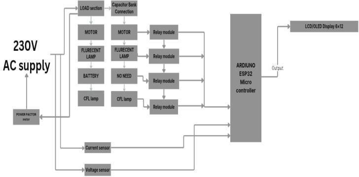
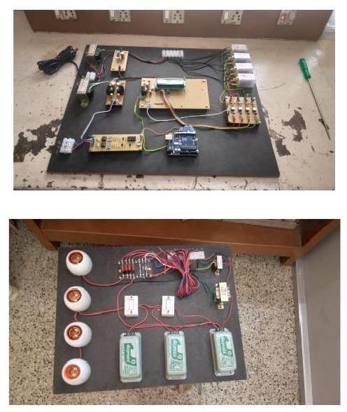
The current Power Factor Correction method uses a microcontroller-based strategy, with Arduino UNO serving as the main controller, combining several components to maximize power factor correction. The system begins with voltage and current transformers reducing high voltage and current levels to Arduino-friendly safe levels for processing. Then, voltage and current sensor circuits transform analog valuesintodigitalones,whichareprocessedbyArduinoUNO todeterminepowerfactor,voltage,andcurrent.Dependingon these calculations, Arduino regulates the capacitor bank through a relay shield to counteract reactive power, thus enhancing power factor. Real-time observation is made possible through an LCD display (20x4), displaying power factor,voltage,andcurrentvalues.Also,a COMportfacilitates communication between Arduino and computer for data logging and analysis. The Power Factor Correction algorithm comprises calculating voltage and current values, finding reactive power compensation, and regulating the capacitor bank. The method enhances power factor, decreases reactive power, increases system efficiency, and facilitates real- time monitoring and automatic control, which makes it appropriate for industrial power systems, commercial buildings, residential, and renewable energy systems. Design considerations for the system include the choice of proper voltage and current transformers, the design of voltage and current sensorcircuits,configurationofcapacitorbank,relay shield, and LCD display interface. Individual component functional testing, system integration testing, and performance validation of the power factor correction ensures the system efficiency. Based on Arduino UNO and components used, the current method achieves an efficient automatedpowerfactorcorrection.


International Research Journal of Engineering and Technology (IRJET) e-ISSN: 2395-0056 p-ISSN: 2395-0072

Volume: 12 Issue: 02 | Feb 2025 www.irjet.net

4.PROPOSED
Power quality is the reliability and stability of electricity delivered to consumers. It guarantees that the voltage, current,andfrequencyarewithintolerablelimitstoprevent electricaldeviceinterruptions.Lowpowerqualitymayresult in voltage sags, swells, harmonics, flicker, and unbalanced loads, all of which can adversely affect electrical equipment, resulting in inefficiency, overheating, and possible failure. Voltage regulation is one of the primary causes of power quality issues. Voltage fluctuations may result from abrupt changes in load demand or power system faults. Volts regulators and automatic tap-changers are utilized to counter these problems. Harmonics, a principal problem, result from nonlinear loads like electronic equipment, fluorescent lamps, and industrial drives. These waveforms' distortions may result in overheating of motors and transformers and consequently energy loss. These are mitigated using harmonic filters, active or passive. Power factor is also a vital parameter of electrical systems that referstohowwellelectricalpowerisutilized.Itisdefinedas the ratio of real power, which performs useful work, to apparent power, which is the total power supplied to a system.Alowpowerfactormeansthatalargeportionofthe supplied power is not being converted into useful work but is instead being lost as reactive power. Inductive loads like motors, transformers, and fluorescent lighting tend to generatealaggingpower factor, i.e.,current lagsvoltage. To correct power factor, techniques are used called power factor correction. The most prevalent technique is through the utilization of capacitor banks, which deliver leading reactivepowertocompensateforthelaggingreactivepower of inductive loads. It alleviates the load from the power system and enhances efficiency. Good power quality and a high power factor are necessary to ensure efficient power system operation. Low power quality results in equipment malfunction,highermaintenancecosts,andlossofenergy.


Likewise, low power factor raises current flow in the system, creating increased transmission losses and penalties from the utility companies. Through the use of voltage regulation, harmonic reduction, transient protection, and power factor correction techniques, utilities and industries can provide stableandefficientelectricalsupplyofpower.

Capacitor banks help boost the power factor by providing reactive power to the network. This reactive power compensatesfortheinductivereactivepowerofthenetwork, thusboostingthetotalpowerfactorandreducingtheburden ongeneratorsandtransformers.
Table -1: Specification
RelayModule Controlled Load Pin (Arduino)
Relay1 Fluorescent Lamp D5
Relay2 Incandescent Lamp NotRequired none Relay3 Motor D6
4.2
Verify PF Correction Efficiency: Measure before/after PF improvement.
THD Reduction Analysis: Ensure THD is within IEEE-519 standards(<5%forvoltage,<8%forcurrent).
LoadVariationTesting:Checksystemresponsetoloadchanges.
4.3
Regular Monitoring: Check the performance of the capacitorsandcontrollersettingsatregularintervals.


Volume: 12 Issue: 02 | Feb 2025 www.irjet.net

Harmonic Reanalysis: For Re-evaluating THD levels and makingfilteradjustments,ifnecessary.
CapacitorBankInspection:Checkforoverheating,bulging, ordeterioration.

CapacitorBank&ControllerInstallation:Parallelconnection ofcapacitorbankstoloadsandimplementcontrollogic.
CTInstallationforFeedback:Putcurrenttransformers(CTs) ontheprimarysupplyfortrackingreactivepower requirement.
IncreaseEnergyEfficiency–Reducetransformer&cableloss


4.5 BENEFITS
Thebenefitsthatcanbeachievedthroughtheutilizationof theappropriate
• power factor correction are: Reduction in power consumptionduetoimprovedenergyefficiency.
• Reduced power consumption results less greenhousegasemissionsandfossilfueldepletion ofpowerstations.
• MorekVAcan be drawnfromtheavailablesupply only.
• Reduction of I2R losses in transmission and distributionequipment.
• Reducingvoltagedropinlongcables.
• Long equipment life – Reduced electric load on electricalcablesandequipment.
Power Factor Improvement: Normally greater than 0.95 . Reduction of THD: Keeps THD within acceptable limits. EnergyCost Savings:Reduction of penaltyand energyloss. System Efficiency: Improved voltage stability and reducedtransformerandcableoverloading.


International Research
Volume: 12 Issue: 02 | Feb 2025 www.irjet.net

The power factor was also enhanced from 0.82 to 0.96 followingtheenergizationofthecapacitorbank.Further,the THD decreased from 18% to 4%, The system also proved stable operation with no overcompensation or instability withloadfluctuations.
In contrast to conventional static capacitor banks, the new system provides dynamic compensation based on power factor and harmonic conditions in real time. Overcompensation or instability, particularly during fluctuating loads or changing harmonic distortions, is a typical problem of conventional systems. Combining harmonic filters with capacitive compensation ensures power factor correction as well as mitigation of THD simultaneously, delivering a more reliable and efficient solution.
SDG 7: Affordable and Clean Energy
Powerfactorcorrectionand THDreductionimprove energy efficiency by ensuring that the electrical system uses power more effectively, reducing losses and enhancing the reliability of the energy supply. This contributes directly to SDG 7's goal of providing affordable, reliable, and sustainableenergyforall.
SDG 9: Industry, Innovation, and Infrastructure
The application of automatic capacitor bank control to improvepowerfactorandreduceTHDdirectlysupportsthe development of resilient infrastructure, promoting efficient and sustainable industrial processes. By ensuring that energy systems are optimized, industries can reduce operationalcostsandimproveenergyperformance.
SDG 13: Climate Action
Byimprovingenergyefficiencyandreducingwaste(through lower THD and better power factor), the overall carbon footprint of energy use can be reduced. Efficient systems require less energy generation, which can lead to lower greenhousegasemissionsandhelpcombatclimatechange.
The proposed automatic capacitor bank system delivers a robust method of enhancing the power factor as well as overall harmonic distortion within electrical systems. Through dynamic setting of capacitor bank stages and embedding harmonic filters, the system achieves not only

of Engineering and Technology (IRJET) e-ISSN: 2395-0056 p-ISSN: 2395-0072

compensation of the power factor but also minimizes the negative impacts of harmonics. Experimental results show the capability of the designedsystem to improve powerquality, increase energyefficiency, and extend the lifespan of electrical equipment. Future research will be aimed at optimizing the control algorithms for improved system performance in complicated industrial applications.
"Automatic Capacitor Bank Control for Power Factor Correction and Harmonic Reduction", J. Liu et al., IEEE Power and Energy Society General Meeting, pp. 1-5, 2018.
"PowerFactorCorrection andTHD ImprovementUsing FuzzyLogicControlledCapacitorBank",A.Kumaretal., International Conference on Power Electronics and DriveSystems,pp.115-120,2019.
"Real-Time Power Factor Correction Using Automatic Capacitor Bank Control", S. S. Rao et al., IEEE International Conference on Industrial Technology, pp. 145-150,2020.
"Power Factor Correction and Harmonic Reduction UsingAutomaticCapacitorBankControl",S.K.Goswami et al., Journal of Electrical Engineering, Vol. 102, No. 1, pp.23-32,2020.
"Automatic Power Factor Correction Using Thyristor Switched Capacitor Bank", A. K. Singh et al., Journal of PowerElectronicsandDriveSystems,Vol.14,No.2,pp. 123-134,2019.
"Real-Time Power Factor Correction Using Fuzzy Logic Controlled Capacitor Bank", M. A. El-Gammal et al., Journalof Intelligent Systems, Vol. 29, No. 1, pp. 53-64, 2020.
"DesignandImplementationofAutomaticPowerFactor Correction System Using Capacitor Bank Control", S. S. Rao, Master's Thesis, Indian Institute of Technology, 2018.
"Power Factor Correction and Harmonic Reduction Using Automatic Capacitor Bank Control", A. K. Singh, Ph.D. Dissertation, National Institute of Technology, 2020.
