
International Research Journal of Engineering and Technology (IRJET) e-ISSN: 2395-0056
Volume: 12 Issue: 02 | Feb 2025 www.irjet.net p-ISSN: 2395-0072


International Research Journal of Engineering and Technology (IRJET) e-ISSN: 2395-0056
Volume: 12 Issue: 02 | Feb 2025 www.irjet.net p-ISSN: 2395-0072
Dr. S.M. Kannan 1 , S. Joshua2 , K.B. Lakshmi Narayanan3, R. Kaushal4, R.R. Dhaya Vishnu5
1 Prof & HOD/EEE, Department of Electrical & Electronics Engineering, K.L.N. College of Engineering, Tamil Nadu, India
2, 3, 4, 5 UG Scholar, Department of Electrical & Electronics Engineering, K.L.N. College of Engineering, Tamil Nadu, India ***
Abstract - Electric vehicle-to-vehicle (V2V) charging allows EVs to share energy, but current solutions have limitations. Off-board V2V systems increase cost and require additional space, while on-board methods using type-2 chargers suffer from inefficient power conversion. This work introduces a direct battery-to-battery V2V charging method that utilizes type-2 AC charger input ports and switches, bypassing active rectifiers to reduce conversion losses and improve efficiency. The effectiveness of the proposed approach is demonstrated through MATLAB/Simulink simulations and a scaled experimental prototype.
Keywords- Vehicle-to-Vehicle (V2V), Charging-Electric Vehicle (EV), Direct Battery Connection, Power Transfer Efficiency, Type-2 AC Charger.
Electric vehicles (EVs), which use electric motors instead of gasoline engines, have gained significant popularity, especially among those committed to environmental sustainability. However, many may not realize that EV technologydatesbacktotheearly19thcentury.Whilethe exact origins of the first EV remain uncertain, electric motors were already in use in the early 1800s. In 1828, Anyos Jedlik developed a small-scale model car powered by an electric motor. Later, between 1832 and 1839, Scottish inventor Robert Anderson built a larger electric motorthatwasusedtodriveacarriage.
Although these early electric vehicles did not achieve widespread adoption, they inspired further innovation.In1835,twosmall-scaleelectricvehicleswere independently developed one in Holland and another in the United States by Thomas Davenport. Davenport later built the first battery-powered electric car, but the use of non-rechargeablebatteriesseverelylimiteditsrange.Over time, inventors such as French engineer Gaston Planté workedonimprovingbatterytechnology,yetpracticalEVs remainedoutofreach.
In modern EV technology, vehicle-to-vehicle (V2V) charging systems primarily depend on either offboard power-sharing interfaces or on-board type-2 chargers. While off-board solutions offer flexibility, they come with added cost and space requirements. On the
other hand, on-board type-2 charger-based V2V power transfer involves multiple conversion stages, resulting in energy losses due to redundant power processing. These challenges emphasize the need for a more efficient, costeffective, and streamlined approach to V2V energy transfer.
Thiswork introducesaninnovative V2Vcharging method that enables direct battery-to-battery energy transfer between two EVs using type-2 AC charger input ports and switches. Unlike conventional methods that depend on active rectifiers for power conversion, this approach eliminates unnecessary rectification and conversion stages. By utilizing a minimal number of switches, the system establishes a direct energy transfer pathway, significantly reducing power losses and improvingoverallefficiency.
To evaluate the feasibility of this method, a comprehensive MATLAB/Simulink simulation is conducted to examine different V2V charging scenarios. Furthermore, a scaled experimental prototype is developed to validate its real-world applicability. The results demonstrate that the direct battery connection approachprovidesahighlyefficientandpracticalsolution forV2Vpowertransfer,pavingthewayformoreadvanced andoptimizedEVchargingtechnologies.
On-boardType-1andType-2electricvehicle(EV) chargers generally consist of an AC-to-DC converter (active rectifier) stage, followed by a DC-DC converter responsible for constant current and constant voltage (CCCV)chargecontrol.Avehicle-to-vehicle(V2V)charging methodcanbeimplementedbyconnectingtheinputports of two Type-1 chargers, as shown in Figure 1(a). In this approach, the provider EV’s battery supplies DC power, which is first converted into single-phase AC using its bidirectional Type-1 charger. This AC output is then used as the input for the receiver EV’s Type-1 charger, which convertsitback toDCtochargeits battery.However,this method results in energy losses due to multiple conversionstages,reducingoverallchargingefficiency.
© 2025, IRJET | Impact Factor value: 8.315 | ISO 9001:2008 Certified Journal | Page519

International Research Journal of Engineering and Technology (IRJET) e-ISSN: 2395-0056
Volume: 12 Issue: 02 | Feb 2025 www.irjet.net p-ISSN: 2395-0072
An alternative V2V charging method involves directly connecting the DC-links of the two EVs using mechanicalswitches,asshowninFigure1(b).However,in practical applications, direct access to the DC-link of the battery-side DC-DC converter is not typically available, makingthismethodchallengingtoimplement.
To overcome these challenges, this work introduces a V2V charging approach that leverages onboard Type-2 chargers. By directly linking the Type-2 chargingportsoftwoEVs,thismethodeliminatestheneed for additional hardware or extra power inlet ports. The proposed approach utilizes the active rectifier stages of thechargersasaconnectioninterfacebetweenthetwoEV batteries,reducingthenumberofconversionstagesinthe power transfer process. Fewer conversion stages mean fewer active switching components, leading to lower switching and conduction losses, which significantly enhancesoverallefficiency.
The proposed system includes a mode selection logic that determines whether the converter should operateinbuckorboostmodebasedonthevoltagelevels of the batteries. It also manages the direction of power flowbasedontheuser’spreference,allowingenergytobe transferred between EVs regardless of differences in batteryvoltageratings.
In this setup, the two EVs are connected through theirexistingType-2chargingports.Thepowertransferis facilitated using the three-phase active rectifier switches. Specifically, during V2V charging, the top switch of one phase (phase-a, denoted as S1) and the bottom switch of another phase (phase-c, denoted as S6) of the provider EV’s active rectifier-1 are turned ON. Simultaneously, the corresponding switches (S’1 and S’6) of the receiver EV’s activerectifier-2arealsoactivated.Thisdirectconnection between the intermediate DC-links of both EVs is illustratedinFigure2.
During the entire V2V charging process, the four switches (S1, S6, S’1, and S’6) remain ON, forming a dual bidirectional buck-boost converter. This configuration allows controlled energy transfer between the two EVs in either direction, regardless of differences in their battery voltage levels. Since the active rectifiers of both Type-2 chargers function as an interface for connecting the two DC-links, their original rectification function is bypassed, and all other switches of the rectifiers remain OFF during V2V charging. Depending on the voltage levels of the two EV batteries, the system operates in different energy transfer modes, ensuring efficient and flexible power exchange.
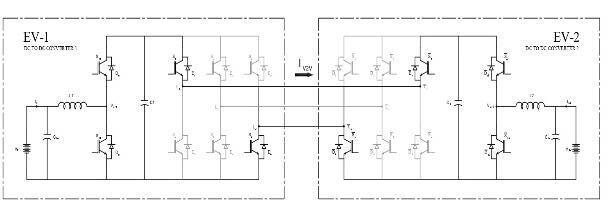
2.1 V2V Scenario-1: Vbat1 < Vbat2
When the battery voltage of EV-1 is lower than that of EV-2, and their roles as provider and receiver are defined,twopossibleoperatingscenariosarise.Inthefirst case, when EV-1 serves as the provider, power flows forward,requiringaboostoperationtostepupthevoltage before transferring energy to EV-2. Conversely, in the secondscenario,whenthepowerflowisreversedandEV2 becomes the provider, a buck operation is needed to step down the voltage before delivering power to EV-1. These operational modes ensure efficient energy transfer between the two EVs, regardless of their battery voltage differences.
1) Forward Boost Mode (EV1 as Provider and EV2 as Receiver):
In this mode, EV-1 acts as the charge provider, whileEV-2functionsasthechargereceiver,withbattery-1 having a lower voltage than battery-2. Once the two EV batteries are directly connected using the proposed approach by turning on switches S1, S6, S’1, and S’6, the voltage of EV-1's battery is boosted to match that of EV-2 byoperatingDC-DCconverter-1inboostmode.Duringthe ON period of switch Sb1, inductor L1 stores energy from EV-1's battery, while switch Sa1 is switched complementarilytoSb1
WhenSb1 turnsOFF,Sa1 turnsON,allowingenergy transfer from EV-1's battery and inductor L1 to EV-2's battery through S1, S’1, Sa2, and inductor L2. To facilitate powerreceptionfromtheDC-links,switchSa2 remainsON throughout the V2V charging process, ensuring that Vdc1 equalsVdc2,whichisequaltoVbat2.Meanwhile,switchSb2 is switched complementarily to Sa2, as illustrated in the figure.
2) Reverse Buck Mode (EV1 as Receiver and EV2 as Provider):
Similartotheforwardboostmode,inthisreverse buck mode, the EV batteries are connected by turning on switchesS1,S6, S’1,andS’6 ofactive rectifiers1and2. The DC-DC converter-1 operates in buck mode to transfer powerfromEV-2’sbatterytoEV-1’sbattery.SinceVbat1is lower than Vbat2, diode Da2 becomes forward biased, ensuring that Vbat2 equals Vdc1, which in turn equals Vdc,

International Research Journal of Engineering and Technology (IRJET) e-ISSN: 2395-0056
Volume: 12 Issue: 02 | Feb 2025 www.irjet.net p-ISSN: 2395-0072
allowing EV-2’s battery to supply power to EV-1 through theDC-link.
During the ON period of switch Sa1, energy from EV-2’sbatteryistransferredtoEV-1’sbatteryviainductor L1, Da2, S’1, and inductor L2, as illustrated in Figure 4(a). When Sa1 turns OFF, the stored energy in inductor L1 is released through switch Sb1, which operates complementarilytoSa1,asshowninFigure4(b).
2 2 V2V Scenario-2: Vbat1 = Vbat2
In this scenario, where both EV battery voltages are equal, the DC-DC converters must be controlled such that one operates in a current-controlled boost mode while the other functions in a current-controlled buck mode.
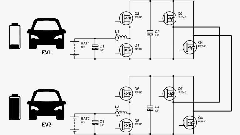
1) Forward Boost Mode (EV1 as Provider and EV2 as Receiver):
In this mode, where Vbat1 equals Vbat2, power transfer from EV-1 to EV-2 is achieved by operating DC-DC converter-1inboostmodeandDC-DCconverter-2inbuck mode, both under closed-loop current control. During the ON period of switch Sb1, inductor L1 stores energy from EV-1’s battery, while switch Sa1 is switched complementarily to Sb1. Simultaneously, switch Sb2 of DCDC converter-2 is turned ON to allow inductor L2 to freewheel energy, with switch Sa2 complementarily switchedtoSb2,asillustratedinFigure5(a).
WhenSb1 andSb2 turnOFF,switchesSa1andSa2turn ON,facilitating energytransfer fromEV-1’s battery toEV2’s battery through L1, S1, S’1, and L2, as shown in Figure 5(b). This mode can also be achieved by controlling the providerEV’sDC-DCconverterinvoltagecontrol modeto regulate the DC-link voltage at a level higher than the EV battery voltage, while the receiver-side DC-DC converter operatesincurrentcontrolmode
2) Reverse Boost Mode (EV1 as Receiver and EV2 as Provider):
This mode is similar to the forward boost mode, where Vbat1 equals Vbat2, but with the power flow
reversed.Inthiscase,DC-DCconverter-2operatesinboost mode, while DC-DC converter-1 functions in buck mode under closed-loop current control. Alternatively, voltage control mode can also be used to regulate power flow in thismode.
2.3 V2V Scenario-3: Vbat1 > Vbat2
Theconverteroperationinthisscenarioissimilar totheScenario-1withthepowerflowdirectionreversed.
1) Reverse Boost Mode (EV1 as Receiver and EV2 as Provider):
This mode is similar to the forward boost mode, where Vbat1 is less than Vbat2, but with the power flow reversed. In this case, the DC-DC converter-2 of EV-2 operates in boost mode, while switch Sa1 of the DC-DC converter-1inEV-1remainscontinuouslyON.
2) Forward Buck Mode (EV1 as Provider and EV2 as Receiver):
Thismodeissimilartothereversebuckmode,where Vbat1islessthanVbat2,but withthepowerflowreversed. In this case, the DC-DC converter-2 of EV-2 operates in buck mode, while switch Sa1 of the DC-DC converter-1 in EV-1remainscontinuouslyON.
The charging rate and the amount of energy transferred in the proposed V2V approach are regulated throughthecontroloftheon-boardconverters.Themode selector flow, as shown in Figure 6, determines the appropriate V2V mode based on the battery voltages of EV-1 and EV-2, along with their designated provider and receiver roles. Additionally, depending on the selected mode of operation, the on-board charger converters are controlled accordingly to facilitate the V2V energy transfer.
Under normal three-phase AC charging using a type-2 charger, the active rectifier operates in d-q control mode to convert three-phase AC to DC while ensuring unity power factor at the grid terminals. However, in the proposed V2V charging approach, the active rectifier is repurposed as an interface to connect and enable energy transfer between the batteries of the two EVs. Once the type-2 charger ports are linked for V2V charging, the gatingpulsesforswitchesS1 andS6oftheactiverectifier-1 in EV-1, along with switches S1 and S’6 of the active rectifier-2inEV-2,remaincontinuouslyactivethroughout theV2Vchargingprocessforalloperatingmodes.

Volume: 12 Issue: 02 | Feb 2025 www.irjet.net p-ISSN: 2395-0072
In the proposed V2V charging approach utilizing onboard chargers, the DC-DC converters of type-2 chargers operate under closed-loop current control. For forwardboostandreversebuckmodes,whereVbat1 isless thanVbat2,theinductorcurrentIL1 ofDC-DCconverter-1is regulated through a closed-loop system. The error between the reference current IL∗I^*_LIL∗ and the actual inductor current IL1 is fed into a PI controller, which generates the duty ratio for switch Sa1, while Sb1 is switchedcomplementarilytoSa1,asillustratedinFigure7. The gating signal for switch Sa2 remains continuously activethroughoutthismode.
The transfer function used to tune the PI controller for DC-DC converter-1 is determined by the duty ratio (D) and the load resistance (R2), which correspondstothechargingcurrentofEV-2’sbattery.The proposed V2V approach offers higher efficiency, reduced losses, and the convenience of connecting two EVs using theexistingtype-2chargerports,makingitapracticaland adaptablesolutionforEVusers.
For any V2V implementation, access to onboard instrumentation sensors and battery management system (BMS)controllersinboththeproviderandreceiverEVsis essential to enable communication between the two vehiclesandretrievethenecessaryparametersforenergy transfer. The bidirectional power converter interface for V2V charging is available, assuming that commercial EVs have built-in communication capabilities, along with accesstocontrollersandinstrumentationsensors.
TheV2Vmodeselectiondependsonbatteryvoltagelevels, providerandreceiverpreferences,anduserinputs,which areobtainedthroughonboardinstrumentationsensors.As depicted in Figure 6, the onboard DSP controllers determinethemodeofoperation(e.g.,forwardboost)and regulate the power flow direction and the required amountofenergytransferaccordingly.
4. HARDWARE DESCRIPTION
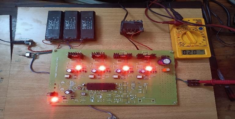
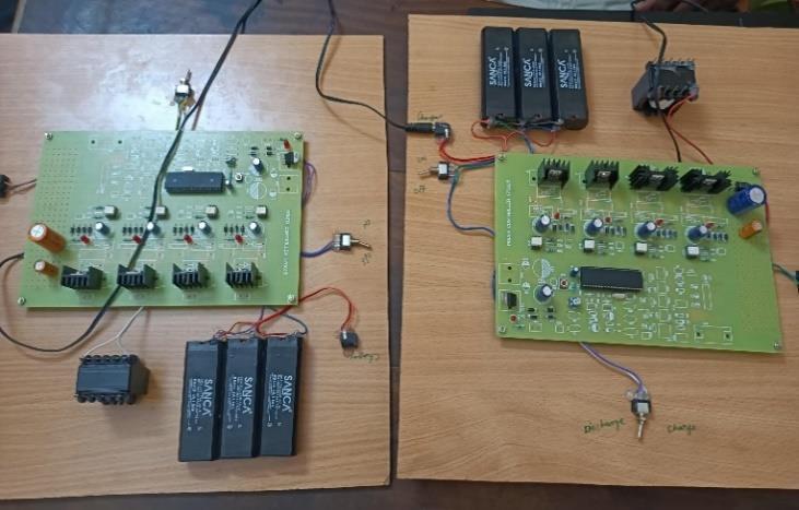
The IRF840 is an N-Channel Power MOSFET capable of switching loads up to 500V and handling currentsofupto8A.Itrequiresagatethresholdvoltageof 10VacrosstheGateandSourceterminalsto
turn on.Duetoitshighgate voltagerequirement, itcannotbedirectlyinterfacedwiththeI/OpinofaCPU.If a MOSFET with a lower gate voltage is preferred, alternativessuchastheIRF540Nor2N7002canbeused.
The PIC16F877 is a highly advanced microcontroller from Microchip, widely utilized for both experimental and modern applications due to its affordability, versatility, high performance, and easy availability. It is well-suited for applications such as machine control, measurement devices, and educational purposes.
5. SIMULATION DESIGN, SDG ADDRESSED & RESULTS
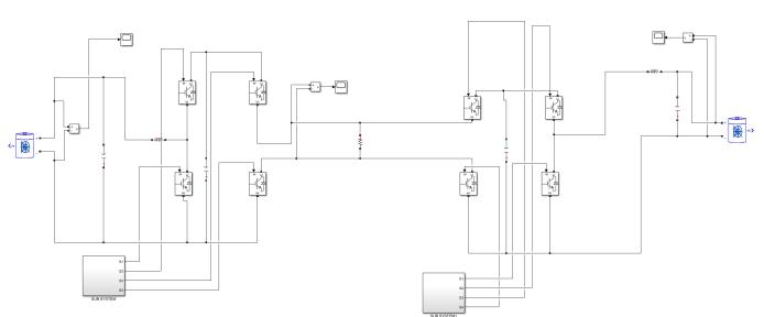
5.1: Overall Simulink model
The simulation model represents a peer-to-peer Electric Vehicle (EV) charging system, enabling one EV to supplypowertoanother.Thissetupisdesignedtoaddress situations like emergency charging in remote locations. Developed using MATLAB/Simulink (version 2020b), the simulationfeaturesbothdonorandreceiverEVsequipped with 48V, 100Ah batteries, ensuring a balance between energystoragecapacityandportability.

International Research Journal of Engineering and Technology (IRJET) e-ISSN: 2395-0056
Volume: 12 Issue: 02 | Feb 2025 www.irjet.net p-ISSN: 2395-0072
Affordable and Clean Energy (SDG Goal 7):
EV charging systems encourage the adoption of electric vehicles, reducing reliance on fossil fuels in transportation.Byusingcleanenergysourceslikesolaror wind for charging, EVs contribute to a cleaner, more sustainable energy ecosystem, aligning with the goal of increasingtheuseofrenewableenergy.
Climate Action (SDG Goal 13):
Smart EV charging infrastructure can seamlessly integratewithrenewableenergysources
suchassolarandwind.Technologieslikevehicleto-grid (V2G) and vehicle-to-vehicle (V2V) power sharing contribute to balancing the energy grid while reducing dependenceonfossilfuels,fosteringatransitiontowarda low-carboneconomy.

5.2:
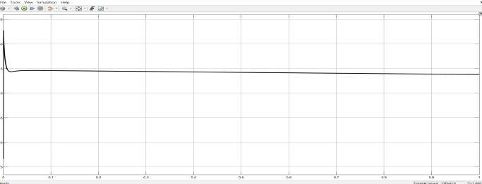
The output voltage remains stable at 90V, with minimal fluctuations of less than ±1% ripple. The system quickly stabilizes at 90V within a few milliseconds, demonstrating the efficiency of the converter's control algorithm.
5.3:
5.4:
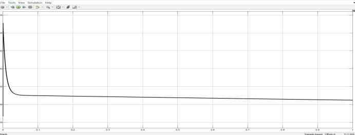
Like the 90V output, the 38V output remains stable with minimal voltage ripple. This lower voltage level provides safe and efficient charging for auxiliary systems. While it stabilizes slightly slower than the 90V output, the control settings are intentionally less aggressivetoprioritizesafety.
This work presents a direct vehicle-to-vehicle (V2V)chargingapproachforpower transfer betweentwo EVs without requiring external hardware or additional charging ports. It serves as an emergency charging solution when AC grid access or DC fast-charging stations are unavailable. By enabling direct battery connection through onboard charger ports, this method significantly reduces hardware infrastructure costs. Eliminating redundant power conversion stages enhances overall efficiency, as demonstrated in the performance analysis. The proposed V2V approach helps alleviate range anxiety andfacilitatescooperativeenergysharingamongEVusers with minimal infrastructure and cost. Its effectiveness is validated through MATLAB/Simulink simulations and experimental results, proving its practicality without alteringtheEVpowerarchitecture.
[1] S. D. Vasconcelos et al., "Assessment of Electric Vehicles Charging Grid Impact via Predictive Indicator,"inIEEEAccess
[2] Y. Tian et al., "Control Multiplexing and Switching Methods for Bi-Directional EV Chargers," 2024 InternationalConferenceonEnergyandElectrical Engineering (EEE), Nanchang, China, 2024, pp. 17.
[3] J. Yang, G. C. Lim, C. Hwang and J. -I. Ha, "TwoPhase DC Charging Method for Improved Efficiency and Zero Torque in Motor-Integrated Charger," in IEEE Transactions on Industrial Electronics
[4] H. Yang et al., "Optimization Scheduling Method for Electric Vehicle Charging and Swapping Stations Based on Elastic Load Regulation Potential," 2024 IEEE 2nd International Conference on Image Processing and Computer Applications (ICIPCA), Shenyang, China, 2024, pp. 1962-1966.
[5] K. Arulvendhan, S. K. Nagaratnam, R. Narayanamoorthi, A. H. Milyani, S. Alghamdi and M.Alruwaili,"PrimarySideHybridReconfigurable Compensation for Wireless EV Charging with Constant Current/Constant Voltage Control," in IEEEAccess,vol.12,pp.149960-149976,2024
[6] P.Vinay,S.K.Suresh,V.D.Ganesh,T.V. Krishna,A. S.GaneshandC.Saiprakash,"DesignandAnalysis of Rotor Technology for Electric Vehicle

International Research Journal of Engineering and Technology (IRJET) e-ISSN: 2395-0056
Volume: 12 Issue: 02 | Feb 2025 www.irjet.net p-ISSN: 2395-0072
Application," 2023 International Conference on Power, Instrumentation, Energy and Control (PIECON),Aligarh,India,2023,pp.1-4.
[7] S.RandR.Manjunatha,"DesignandTestingofan Integrated Electric Vehicle Model," 2021 IEEE Mysore Sub Section International Conference (MysuruCon),Hassan,India,2021,pp.703-710
[8] S. B. Kazeem Pasha and V. Champa, "Design and Development of Regenerative Suspension System for EV Applications," 2023 IEEE International ConferenceonPowerElectronics,SmartGrid,and Renewable Energy (PESGRE), Trivandrum, India, 2023,pp.1-5.
[9] M. H. S. M. Haram, M. T. Sarker, G. Ramasamy and E. E. Ngu, "Second Life EV Batteries: Technical Evaluation, Design Framework, and Case Analysis," in IEEE Access, vol. 11, pp. 138799138812,2023
[10] V. P. Keseev, "Electric Bicycle Design Experiences and Riding Costs," 2020 7th InternationalConferenceonEnergyEfficiencyand AgriculturalEngineering(EE&AE),Ruse,Bulgaria, 2020,pp.1-4
2025, IRJET | Impact Factor value: 8.315 |