
International Research Journal of Engineering and Technology (IRJET) e-ISSN: 2395-0056
Volume: 12 Issue: 01 | Jan 2025 www.irjet.net p-ISSN: 2395-0072


International Research Journal of Engineering and Technology (IRJET) e-ISSN: 2395-0056
Volume: 12 Issue: 01 | Jan 2025 www.irjet.net p-ISSN: 2395-0072
Karthik Rajendran1
Abstract - This journal explores the conceptual design of incorporating Vertical Take-Off and Landing (VTOL) capabilities into the Skywalker X8, with the aimof achievinga hybrid VTOL system that meets specific performance criteria. The primary objective is to demonstrate the feasibility of developing a VTOL-enhanced version of the Skywalker X8 while adhering to stringent performance requirements. The proposed design focuses on achieving an All-Up Weight (AUW) of under 7 kilograms, a critical threshold for regulatory compliance and optimized payload capacity. By integrating advanced VTOL mechanisms, the modified Skywalker X8 is intended to maintain a minimum endurance of 2 hours, which is essential for applications such as aerial photography, surveillance, and mapping. This endurance is crucial for extended flight operations, enablingthe aircraft to perform prolonged missions effectively. Additionally, the designaims to ensure operational capability at altitudes up to 1000 meters Above Mean Sea Level (AMSL). This altitude flexibility is intended to enhance the aircraft’s usability across diverse geographical and environmental conditions, providing adaptability to various mission profiles. The system also targets a range capability of at least 15 kilometres, therebysupportingextendedmissionsandbroader coverage areas, which is vital for comprehensive data collection and surveillance tasks.
The journal details the conceptual framework of the VTOL system, including designmodifications,integrationchallenges, and expected performance impacts. Preliminary simulations and analysis are presented to validate the proposed design and assess its feasibility in meeting the outlined performance requirements. The findings indicate promising potential for the hybrid VTOL system, providing a foundation for future development and refinement.
This document is template. The Skywalker X8 is a highly regarded unmanned aerial vehicle (UAV) known for its exceptionalperformanceinfixed-wingflight.Withitsrobust design,theSkywalkerX8iswidelyutilizedfortaskssuchas aerial photography, surveillance, and mapping due to its endurance and stability. However, to further enhance its operational versatility, there is a growing interest in integrating Vertical Take-Off and Landing (VTOL) capabilitiesintotheSkywalkerX8’sexistingframework.
To achieve this goal, the design will address several key requirements. Specifically, the aircraft must be capable of take-off and operation at three distinct altitudes: 4500 meters, 5000 meters, and 5500 meters Above Mean Sea
Level (AMSL). These varying altitudes present significant challenges, including reduced air density and altered aerodynamic conditions, which necessitate precise engineeringanddesignmodifications.
To accommodate these requirements, several design changeswillbeimplemented.Theseincludetheextensionof thewingandtheadditionofboomstointegratetheVTOL propulsion system effectively. These modifications are crucial for ensuring that the aircraft can achieve the necessary lift and stability at high altitudes while maintainingoperationalefficiency.
In addition, the selection of an appropriate airfoil will be guided by existing research literature to ensure optimal aerodynamic performance. Following this, detailed calculations will be performed to determine the required airspeedforbothfixed-wingandVTOLflightmodes.Power calculationswillbeconductedtoassesstheenergyneedsfor bothflightmodes,followedbybatterycapacitycalculations toensurethatthesystemcanmeetendurancerequirements.
Based on the results of these calculations, suitable componentswillbeselectedtomeetthedesignobjectives. ThisapproachensuresthattheSkywalkerX8canachievethe desired performance while integrating VTOL capabilities, therebyexpandingitsoperationalscopeandenhancingits utilityacrossvariousmissionprofiles.
Thefollowingrequirementsaretakenasasampleforwhich this conceptual design must be done. These requirements are derived from the requirements given by various government defence organizations. We have considered threedifferenttakeoffaltitudes,threedifferentoperating altitudes. Also, along with this, the flight time is also specified for each altitude. The climb rate considered is 1m/s.Andtherangeconsideredis15Km.Therequirement oflimitstheoverallweightoftheUAVtobelessthan7Kgs. Pleasefindtheminthebelowtable.
Mission Requirements 1 2 3

International Research Journal of Engineering and Technology (IRJET) e-ISSN: 2395-0056
Volume: 12 Issue: 01 | Jan 2025 www.irjet.net p-ISSN: 2395-0072
Table 1 - Requirement
OurProposedFlyingwingisinspiredfromSkywalkerX8. The Skywalker X8 is a well-established and widely used conventionalfixedwingunmannedaerialvehicle(UAV).Itis known for its stability, payload capacity, and endurance, making it suitable for various applications in the field of unmannedaerialsystems(UAS).Forourspecificconversion plan, the process involves modifying the Skywalker X8's airframebyextendingthewingareaandintegratingaboom systemwithmultiplemotors.TheTargetedAUWis7000g.
This was inspired from the blog https://discuss.ardupilot.org/t/skywalker-x-8-vtolconversion-my-way/66879wherethepracticalflyingmodel hasbeenachieved.
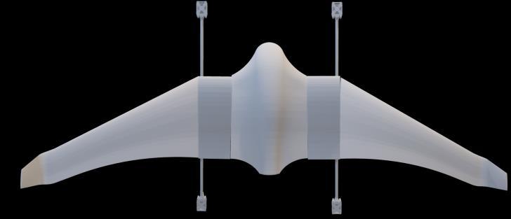
The Aerodynamics of Skywalker X8 is wonderful for lowspeed flying. But as this a swept back wing, the Pitching momentCoefficient(Cm)playsavitalpart. WithreferenceofthePaper“Aerodynamic modelingofthe Skywalker X8 Fixed-Wing UnmannedAerialVehicle”,itis found that the existing design of the Aircraft has a good pitchingmomentCo-Efficient.
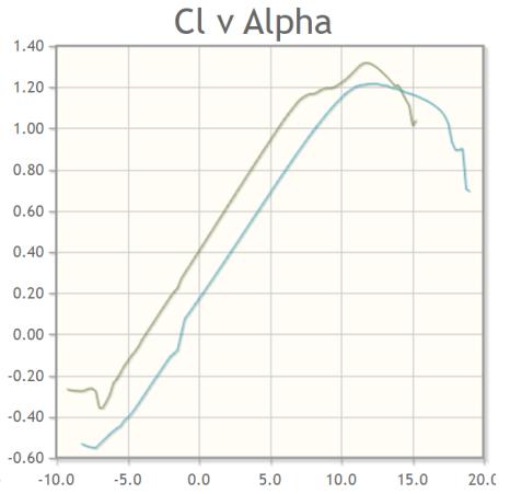
Thegraphispresentedbelow:(Reynoldsnumberconsidered: 4x10⁵and5x105)
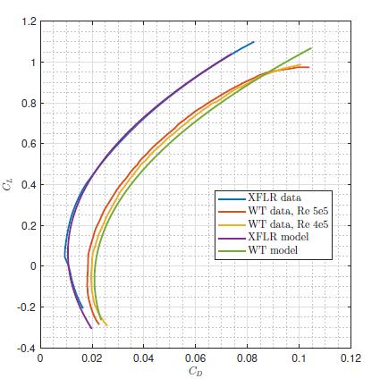
1 – Cl vs Cd
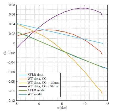
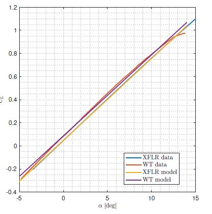
3 – Cl vs AOA
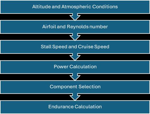
Thepictorialrepresentationbelowshowsustheprocessflow thatwehavetakenupforthisjournal.

Research
Volume: 12 Issue: 01 | Jan 2025 www.irjet.net p-ISSN: 2395-0072
Theselectionofaerofoiliscrucialindesigningaflyingwing, as it significantly influences the aircraft’s stability and efficiency.Aflyingwinglackstraditionaltailsection,relying heavilyontheairfoilshapetomaintaincontrolandlift.
Foranalyzingairfoilcharacteristicsat7000mAMSL,atypical operatingReynoldsnumberisrequired


For analyzing air foil characteristics at 5500m AMSL, a typicaloperatingReynoldsnumberisrequired


Airfoil characteristics have been analyzed for 0.2 million ReynoldsNumber
The Actual airfoil of Skywalker X8 is not disclosed by the Manufacturer, but it closely resembles S5010, so we had consideredthisastheAirfoil.
Similarly, from the reference article:” Airfoil Selection Procedure, Wind Tunnel Experimentation and Implementation of 6DOF Modeling on a Flying Wing Micro Aerial Vehicle”,inthispaper,theyhaveconsidered10 differentairfoils,andfoundthatE387moreaptforaflying wingconfiguration,sowehavetakenthesetwoairfoilsfor ourSkywalkerX8remodeling
Table 2 - Airfoil Comparison


Figure 2 – E387 & S5010 Comparison
4

International Research Journal of Engineering and Technology (IRJET) e-ISSN: 2395-0056
Volume: 12 Issue: 01 | Jan 2025 www.irjet.net p-ISSN: 2395-0072
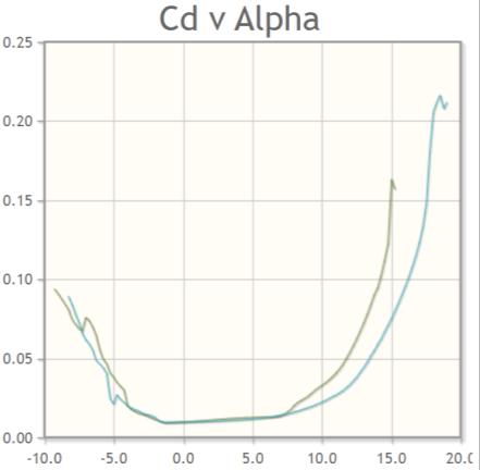
E387
S5010
Graph 5
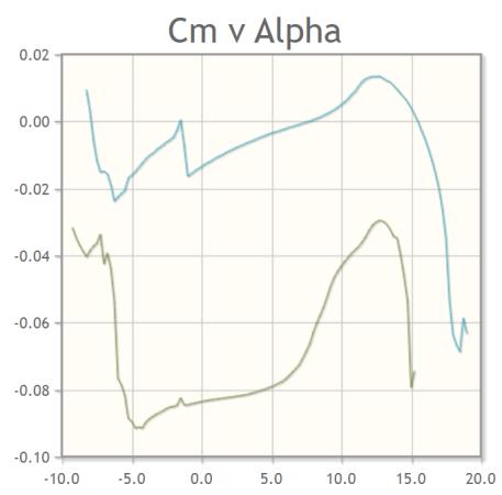
E387
S5010
Graph 6
Althoughwedon’tknowtheactualaerofoiloftheSkywalker X8,wehaddonereverseengineeringandwitha3Dscanned model, we could find that the E387 Airfoil is the closest resemblance to Skywalker X8, For Our Project, We have SelectedE387Airfoilandcarriedoutourcalculations.
4. Calculations
Thecalculationsbelowareconceptualassumptions.
4.1 FW Power Calculation
(Considering ) (Considering )
TheEstimatedDrag=9.719N
TheEstimatedDrag=10N


(Assumed )

Table 3 - FW Power
4.2 VTOL Power Calculation
WhentheUAVisinhover,momentumtheoryalonecanbe usedtocalculatethehoverpower.
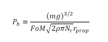


whereFoMisthefigureofmerit.Typicalpropellersachieve afigureofmeritbetween0.5–0.7.Avalueof0.6isused.The geometric pitch of the propeller is not considered by momentumtheory.Thisisconfirmedbyexperimentaldata indicatingthatthepowertoproduceagiventhrustathover doesnotdependonthepropellerpitch.

Table 4 – VTOL Power
4.3 VTOL Battery Capacity estimation
VTOLcapacity:(AssumedTimeforTake-off:2mins,Landing: 2mins)
(DuringTake-off,VoltageConsidered:4Vpercell)
(DuringLanding,VoltageConsidered:3.3Vpercell)
ThetotalBatteryCapacityrequiredfor4minsis mentionedinthetable,thebatteryconsideredis6S1P battery

Table 5 - Battery Capacity required for VTOL

International Research Journal of Engineering and Technology (IRJET) e-ISSN: 2395-0056
Volume: 12 Issue: 01 | Jan 2025 www.irjet.net p-ISSN: 2395-0072
4.4 FW Climb Power Calculation and Battery capacity estimation
TheFixedWingclimbpowercalculationsaredoneasperthe formulabelow

Table 6 - FW Climb Power


(Assumingvoltagepercelltobe3.7)
Table 7 - FW Climb Batt Capacity
4.5 FW Cruise Battery capacity estimation
FWCruisePower:

Table 8 - FW Cruise Power

(Assumingvoltagepercelltobe3.7)
Table 9 - Batt Required for Cruise Power
4.5 Total Battery capacity estimation
Assumingavionicspoweris60Wh,thenthebatterycapacity requiredforAvionicsis
Batteryrequiredforavionics=60/(3.7*6)=2.702Ah
(Assumingvoltagepercelltobe3.7)

Table 10 - Total Battery Required
Basedontheabovepowercalculationsandbatterycapacity estimation, we have selected the following Motors, ESCs, BatteryandPropellers.
The motor has been chosen based on the Climb power requiredatAltitude7000AMSL AT4130-450kVmotor
The motor's design and construction make it suitable for demandingapplicationsandprovideexcellentperformance characteristics.
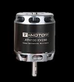

Table 11 – Specifications of AT4130 KV450 Motor
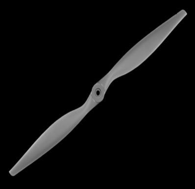
The fixed-wing propeller selection is dependent on the operatingspeedregimeasthepropellerthrusttendstogo zeroataparticularspeedforagivenpropellerpitchandrpm knownaspitchspeed.Thepropellerrecommendedforthe chosenFWenginebyOEMis17-inchx10-inch
PitchSpeed=(RPMofmotorXPropellerPitch/60)X0.025

Table 12 -Pitch Speed – 17x10

International Research Journal of Engineering and Technology (IRJET) e-ISSN: 2395-0056
Volume: 12 Issue: 01 | Jan 2025 www.irjet.net p-ISSN: 2395-0072
Thecruise-regimeof16m/sto18m/sfortheairfoilchosen, therpmrangeisaround4000–5000.Whichisconsiderably higher
Ifwechoseapropellerofsize17-inchx12-inch,followingis thepitchspeedthatweget.

-
Thecruise-regimeof16m/sto18m/sfortheairfoilchosen, therpmrangeisaround3000–4000.whichinacceptable rangeforthechosenFWMotor
With the findings in the motor data, the 3 closest electric propellersavailablearechosenandaretoberunonthrust benchtogetthepropellerperformancedata.

Figure 5 - AT-75A ESC

Table 14 - ESC Specifications
The considered motor Thrust is to weight ratio for this aircraftis2:1
WeightoftheAircraft:7000g Thrustrequiredis2timesof7000gwhichis14000g
ThemotorKDE4215XF-465kVhasbeenconsideredbasedon therequirement
XF-465kV
18.5"X6.3DUALEDN
We are going to choose APC Propellers; These propellers providehighperformanceandlownoise.
Inthis,wehavechosen3propellers
APC17x10E
APC17x12E
APC18x10E
To maintain control and stability during flight, we have chosen the AT-75A 6S T-Motor ESC (Electronic Speed Controller)
The ESC will provide precise control of the motor speed, ensuringthecontinuouscurrentflowwithminimalheating. Features:
InputVoltageAbnormalprotection
LowBatteryprotection
Overheatprotection
ThrottleSignalLossprotection
Table 15 – Specifications of KDE4215XF – 465kV Motor
Withaltitude,electricalpowerisassumedtoremainsame eventhoughitisexpectedtoreduceduetothinair
Withreductioninvoltage,thrustandpowerdropis modelledwhereascurrentisassumedtoremainsame

LowVoltageCorrection:
Testvoltage(Max)=4.35V/cell
Take-offvoltage=4V/cell
Landingvoltage=3.3V/cell
Take-offvoltageratio=0.919
Landingvoltageratio=0.758


International Research Journal of Engineering and Technology (IRJET) e-ISSN: 2395-0056
Volume: 12 Issue: 01 | Jan 2025 www.irjet.net p-ISSN: 2395-0072
5.4.2 VTOL Motor Test data Correction during takeoff
Withtheabovevoltageandvoltageratioandtheformulas wehavetabulatedthecorrectedtestdata
TestDataavailablewith18.5”x6.3DualBladePropeller
Voltage=26.1V(max)
Temperature=295K
Pressure=102600Pa
Density(estimated)=1.2117kg/m3

Table 16 – Actual Thrust data
ThrustDatawithAltitudeCorrection
Densityat5500mAMSL=0.697kg/m3
Electrical Power is assumed to remain the same eventhoughitisexpectedtoreduceduetothinair


Table 17 – Thrust data Altitude Correction
ThrustDatawithVoltageCorrection
TestDataVoltage=26.1V
TakeoffVoltageCondition=26V
TakeoffVoltageratio=0.919
Assumed that the current remains same, while powerandthrustdrops
RESULT

Table 18 – Thrust data Voltage Correction
HoverThrustpermotor=3-3.5kg, Thisthrustcanbeachievedat75%throttle
TotalHoverCurrent=23.7x4=94.8A(75%throttle)
5.4.3 VTOL Motor Test data Correction during landing
ThrustDatawithAltitudeCorrection
Densityat5500mAMSL=0.697kg/m3
Electrical Power is assumed to remain the same eventhoughitisexpectedtoreduceduetothinair


Table 19 - Thrust data Altitude Correction
ThrustDatawithLowVoltageCorrection
TestDataVoltage=26.1V
TakeoffVoltageCondition=19.3V
TakeoffVoltageratio=0.758
Assumed that the current remains same, while powerandthrustdrops

Table 20 – Thrust data Low Voltage Correction

International Research Journal of Engineering and Technology (IRJET) e-ISSN: 2395-0056
Volume: 12 Issue: 01 | Jan 2025 www.irjet.net p-ISSN: 2395-0072
HoverThrustpermotor=3-3.5kg, Thisthrustcanbeachievedat88%throttle
TotalHoverCurrent=35x4=94.8A(88%throttle)
Withthefindingsinthemotordata,the3closestpropellers availablearechosenandaretoberunonthrustbenchtoget thepropellerperformancedata.
WearegoingtochooseKDEandT-MotorPropellers;These propellersprovidehighperformanceandlownoise.
Inthis,wehavechosen3propellers

Tomaintaincontrolandstabilityduringflight,theXROTOR 4IN1ESC-MICRO60Ahasbeenchosen
Features:
High-performance 32-bit microprocessor with a runningfrequencyofupto48MHzforanexcellent performance.
Thecodesupportsregular1-2mspulsewidthinput, as well as Oneshot125 (125-250us), Oneshot42 (41.7-83.3us)andMultishot(5-25us).
The code also supports a beacon functionality, wheretheESCwillstartbeepingafteragiventime ofzerothrottles.Thiscanbeveryusefulforfinding lostcrafts
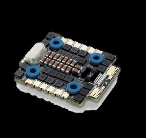

CompatibilitycheckforVTOLpropulsion(DuringTakeoff& Landing):
Hover current at during Takeoff 5500 m AMSL = 94.8A
DischargeRatingatHover=94.8/30=3.16C
Hover current at during Landing 5500 m AMSL = 140A
DischargeRatingatHover=80/30=4.66C
Consideringcurrentat100%throttle
Totalcurrentdrawn=44.9x4=250.4A
DischargeRating=250.4/30=8.33C
Bothabove-mentioneddischargerateconditionsarewithin maximum continuous discharge rate characteristic of the batterypack
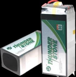
ForbothFWFlightandVTOLconversion,weareusingone solid-stateLi-ionbatteryasthepowersource. Specifically,wehaveplanstousea30000mAh5Csolid-state Li-ionbattery,whichoffershighenergydensityandcapacity. TheTotalBatteryAhestimationrequiredforourcomplete mission is 26.202 Ah We will be using only 90% of the battery,so90%of30Ahis27Ah.
Expanded polypropylene material has been chosen to be usedasmaterialforairframe.Polypropylene(PP)isakindof hemi crystalline thermoplastic plastics. Most commercial polypropylenesareisotacticandhasanintermediatelevelof crystallinitybetweenthatoflow-densitypolyethyleneand high-density polyethylene. EPP is a recyclable closed cell moldedfoamwithanimpressivesetofpropertiesthatyou wouldstruggletofindinanothermaterial

International Research Journal of Engineering and Technology (IRJET) e-ISSN: 2395-0056
Volume: 12 Issue: 01 | Jan 2025 www.irjet.net p-ISSN: 2395-0072
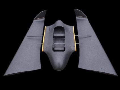

Table 22 – Total Weight Estimation without Harness
6. Conclusion
Inconclusion,thedevelopmentofacompactandagileFlying WingHybridVTOLoffersaviablesolutiontothelimitations commonly associated with conventional fixed-wing UAVs andlargerVTOLsystems.
Also with our Conceptual design we are able to prove the theoretical capabilities of our model achieving the requirementsofthemission.
This project is divided into multiple phases wherein the followingareidentificationofBOM,AvionicsArchitecture, Procurementofmaterials,Subsystemtestingandvalidation, Systemintegrationwithdesignmodifications,Benchtesting andFlighttestinganddatagathering
ACKNOWLEDGEMENT
I would like to Acknowledge and thank Professor A.K.Ghosh(IIT Kanpur), Mr. Mano Prakash(Deputy Manager, Tata Advanced Systems Ltd, Bangalore.), Mr. Sudharshan Konda Reddy(DeputyGeneralManager,Tata
AdvancedSystems,Bangalore)fortheirTechnicalGuidance andMyColleaguesandFamilyfortheircontinuoussupport.
[1] Hossein Hamdani, “Airfoil Selection Procedure, Wind TunnelExperimentationandImplementationof6DOF ModelingonaFlyingWingMicroAerialVehicle”,MPDI, May2020
[2] Kristofer Gryte; Richard Hann; Mushfiqul Alam; Jan Roháč;TorArneJohansen;ThorI.Fosse,“Aerodynamic modeling of the Skywalker X8 Fixed-Wing Unmanned AerialVehicle”

I am Karthik Rajendran an Aeronatical Engineer with 6+ years of experience in UAV System Engineering,Integration, and Testing I have worked in multiple Defence Projects for variouscompaniesinmyCareer.I also bring my expertise in UAV DesigningfromConceptualdesign tofinalproduct.