7 minute read
off on on off off on 0 -Vdc/2 -Vdc/2 0 -Vdc/2

from Reduced Switches Count of Five Level H-bridge Inverter with Integrated Boost Converter
by IJRASET

For mode 7and 8 has two distinct states, gating logic in state (b) as follows y7b = (-Vdc ≤ Vref ≤ -Vdc/2) ∧ ((Vref > Vc1)∨ (Vref > Vc3))
y8b = (-Vdc ≤ Vref ≤ Vdc/2)∧((Vref>Vc2)∨ (Vref > Vc4))
Advertisement
For mode 2, gating logics are y 2 = (-Vdc≤ Vref≤ -Vdc/2) ∧ ((Vref ≤Vc1) ∧ (Vref ≤ Vc2) ∧ (Vref ≤ Vc3) ∧ (Vref ≤ Vc4))
Based on table 3, Logic circuits for each switch can be given as follows [11] Q1 = y1 ∨ y3a ∨ y3b ∨ y5a ∨ y5b ∨ y6a ∨ y6b Q2 = ¬Q1 Q3 = y2 ∨ y3a ∨ y3b ∨ y7a ∨ y7b ∨ y8a ∨ y8b Q4 = ¬Q3 Q5 = y1 ∨ y2 ∨ y5a ∨ y5b ∨ y7a ∨ y7b Q6 = y1 ∨ y2 ∨ y6a ∨ y6b ∨ y8a ∨ y8b
IV. SIMULATION RESULTS AND DISCUSSIONS FOR PROPOSED SYSTEM
The proposed reduced switch count five level H-bridge inverter with integrated boost converter in the solar PV system has been modelled and simulated in MATLAB/SIMULINK environment using simpower system toolbox. The multi carrier phase shifted pulse width modulation technique with sinusoidal reference is used to trigger the switches in reduced switches count five level Hbridge inverter. The circuit was simulated with load. Parameters of solar panel and boost converter are shown in table.1and 2.The proposed system is implemented in 1000w/m2 irradiance and 25degrees C temperature. Parameters of reduced switch count fivelevel H- bridge inverter as shown in below table.4.
Table.4. Simulation Parameters PARAMETERS VALUES Switching frequency 6KHz Output frequency 50Hz Capacitor C1=C2 2200µF Load 10Ω
PV array power, voltage, boost voltage and inverter output voltage values for different irradiations as shown in below table.
Table.5. Output Values for Different Irradiations Irradiation 1000w/m2 900w/m2 800w/m2 700w/m2
PV power 950W 920W 898W 858W
PV voltage 64V 64V 63.9V 63.8V
Boost voltage 100V 100V 100V 100V
Inverter voltage(Vpeak) 100V 100V 100V 100V
The dc output voltage of PV module and DC-DC boost converter and ac output voltage and current of proposed model are given in fig.11, fig.12, fig.13, fig.14, fig.15 and fig.16 respectively. The total harmonic distortions for the output voltage with load are given in fig.17.
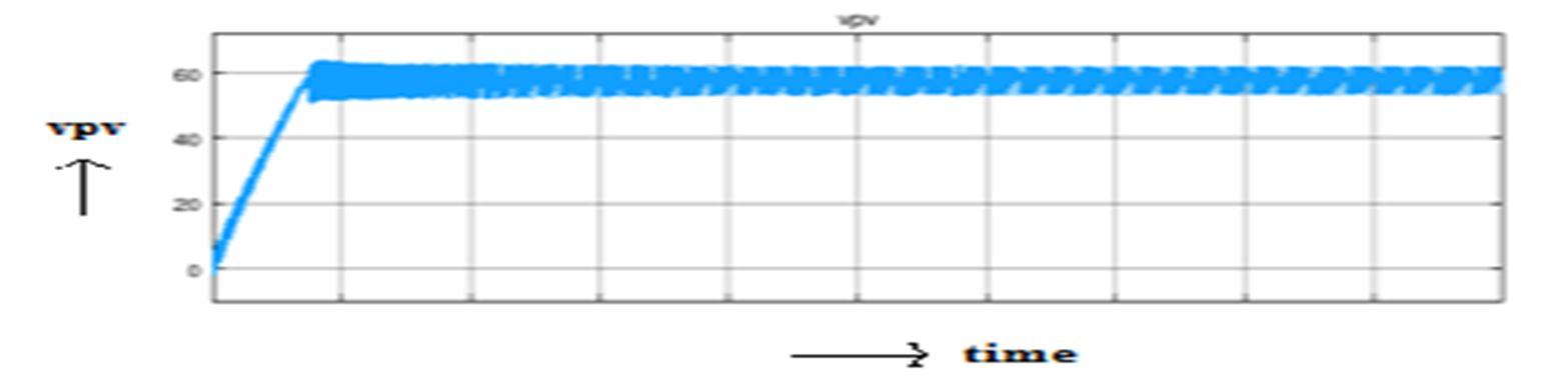
Fig.11. PV Array Output Voltage
In fig. 11 shows the output voltage of PV with irradiance 1000W/m2 and 25degrees temperature.
Fig.12. Boost Converter Output Voltage
In fig.12 shows the output voltage of DC-DC boost converter.
Fig.13. Output Voltage of Inverter
Fig.14. Magnified view of Output Voltage of Inverter
In fig.13 shows the output voltage waveform of a proposed system. The output voltage waveform has 5-levels for one cycle of 50HZ frequency can be observed. Which are -100,-50, 0, 50 and100.
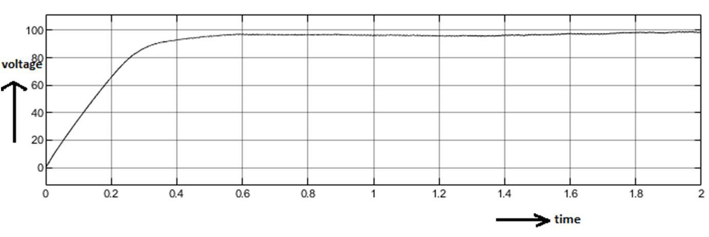
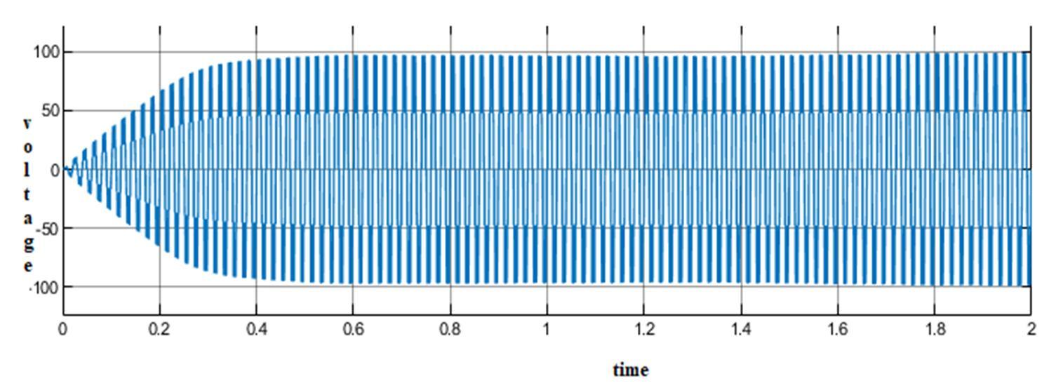
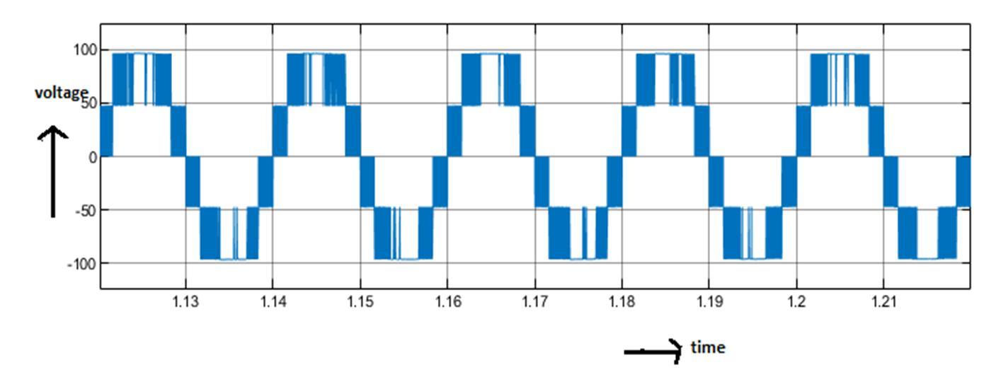
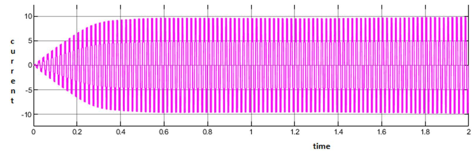
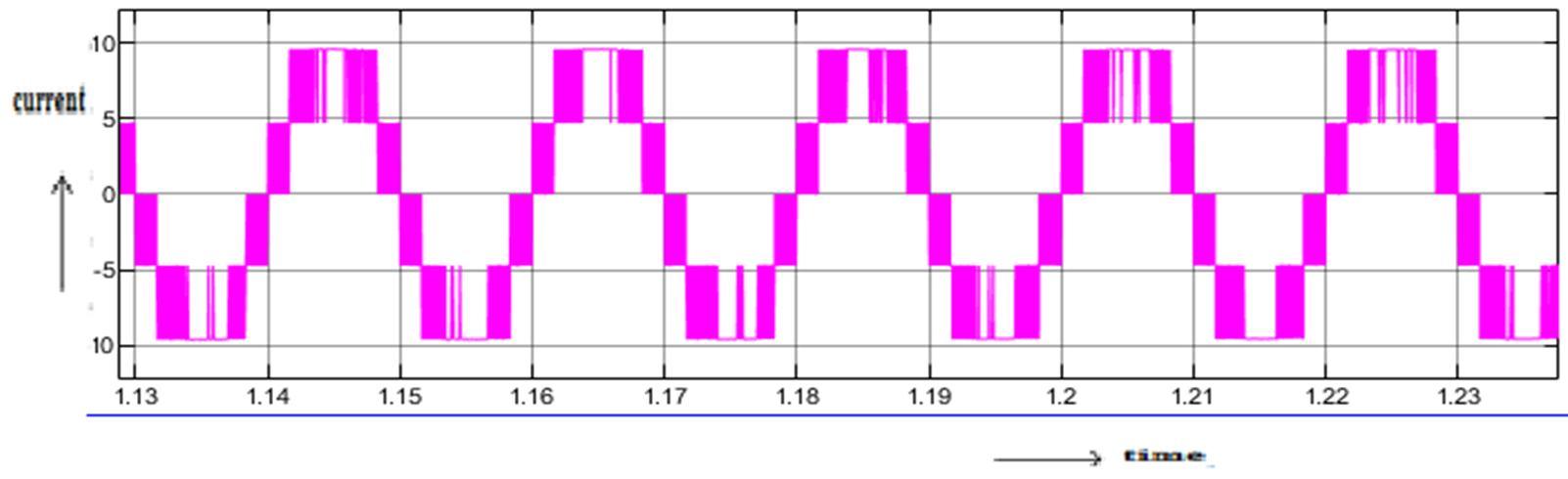
Fig.15. Output Current of Inverter
Fig.16. magnified view of Output Current of Inverter
In fig.15 shows the output current waveform of a proposed system. The output current waveform with peak amplitude of 9.98A
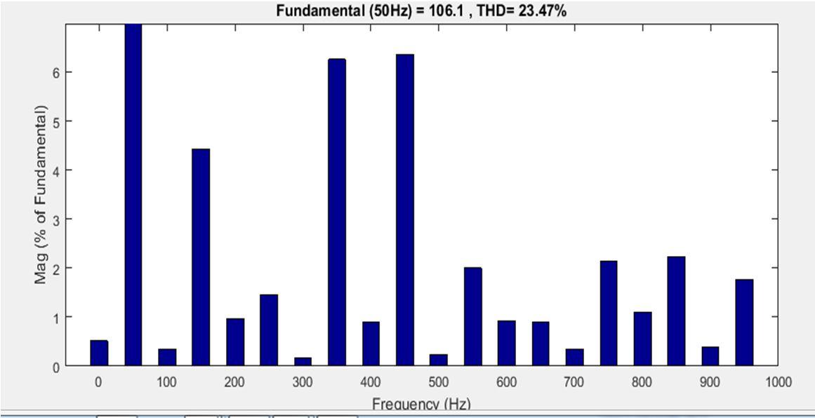
Fig.17. FFT analysis of output voltage
In fig.17 shows the total harmonic distortion (THD) for the output voltage of proposed model with load. To determine the THD present in a waveform, the line spectrum of the output voltage waveform is considered. From the results the proposed system gives reduced THD. As the no.of power switches are reduced power losses and conduction and switching losses will also be reduced.
V. CONCLUSION
In this paper, the proposed reduced switch count five level H-bridge inverter with integrated boost converter in the solar PV system has been modelled and simulated in MATLAB/SIMULINK software. The reduced switches count 5-level H-bridge inverter is connected from one independent solar panel with INC MPPT algorithm instead of Dc source through boost converter. The most important features of proposed system is increasing the no.of output levels with reduced no.of switches and thereby, decreasing the size, complexity, cost, switching and conduction losses and power losses. The proposed model shown to be the one of the best in terms of efficiency and lesser percentage of voltage THD, Simulation results allow us to conclude that the proposed model offers better performance. Hence the proposed system is suitable for PV applications.
REFERENCES
[1] RAJU, R. Goutham Govind et SUBRAMANIAM, N. P. Operation and modelling of photovoltaic power generators. In: Recent Advances in Space Technology
Services and Climate Change (RSTSCC), 2010. IEEE, 2010. pp. 466-469. [2] KUMARI, J. Surya et BABU, Ch. Sai, Mathematical Modelling and Simulation of Photovoltaic Cell using Matlab - Simulink Environment. International
Journal of Electrical and Computer Engineering (IJECE), 2011, vol. 2, no 1, pp. 26-34 [3] LYDEN, S., HAQUE, M. E., GARGOOM, A., et al. Modelling photovoltaic cell: Issues and operational constraints. In : Power System Technology (POWERCON), 2012 IEEE International Conference on. IEEE, 2012. p. 1-6. [4] Vol. 5, Issue 3, March 2016 Copyright to IJAREEIE DOI:10.15662/IJAREEIE.2015.0503112 1694 Analysis of Different MPPT Techniques Athira B1 ,.
Greeshma V2 . Jeena Johnson3 Assistant Professor, Dept. of EEE, Sree Buddha College of Engineering for Women, Pathanamthitta, Kerala, India1 U.G
Student, Dept. of EEE, Sree Buddha College of Engineering for Women, Pathanamthitta, Kerala, India2 U.G Student, Dept. of EEE, Sree Buddha College of
Engineering for Women, Pathanamthitta, Kerala, India [5] J. Rodriguez, J. S. Lai and F. Z. Peng, “Multilevel inverters: A survey of topologies, controls, and applications”, IEEE Trans. Ind. Electron., vol.49, no. 4, pp. 724-738, August 2002. [6] F. Z. Peng, “A generalized multilevel inverter topology with self voltage balancing”, IEEE Trans. Ind. Applicat., vol. 37, no. 2,pp.611-618,March/April2001. [7] J. S. Lai and F. Z. Peng, “Multilevel converters–A new breed of power converters”, IEEE Trans. Ind. Applicat., vol. 32, no. 3, pp.509-517,May/June1996. [8] L.Tolbert, F.Z.Peng and T. Habetler, “Multilevel converters for large electric drives”, IEEE Trans. Ind. Applicat., vol.35,no.1,pp.36-44,Jan/Feb1999. [9] ISHAQUE, Kashif et SALAM, Zainal.An improved modelling method to determine the model parameters of photovoltaic (PV) modules using differential evolution (DE). Solar Energy, 2011, vol. 85, no 9,p. 2349- 2359. [10] Koca, Yavuz & Aslan, Yılmaz & Yonetken, Ahmet & Oğuz, Yüksel. (2019).Boost Converter Design and Analysis for Photovoltaic Systems. [11] Kahwa, Almachius & Obara, Hidemine & Fujimoto, Yasutaka. (2018).Design of 5-level reduced switches count Η-bridge multilevel inverter. 4146.10.1109/AMC.2019.8371060. [12] M. G. Villalva, J. R. Gazoli, E. Ruppert F, "Comprehensive approach to modelling and simulation of photovoltaic arrays", IEEE Transactions on Power
Electronics, 2009 vol. 25no. 5, pp. 1198--1208, ISSN 0885-8993. [13] M. G. Villalva, J. R. Gazoli, E. Ruppert F, "Modeling and circuit-based simulation of photovoltaic arrays", Brazilian Journal of Power Electronics, 2009 vol. 14, no. 1, pp. 35--45,ISSN 1414-8862. [14] R. Sridhar, Dr. Jeevananathan, N. Thamizh Selvan, Saikat Banerjee, “Modeling of PV Array and Performance Enhancement by MPPT Algorithm",
International Journal of Computer Applications (0975 – 8887) Volume 7– No.5, September 2010. [15] HairulNissahZainudin, SaadMekhilef, “Comparison Study of Maximum Power Point
Tracker Techniques for PV Systems”, Cairo University, Egypt, December 19-21, 2010, Paper ID 278. [16] M.H.Rashid, Power electronics handbook, 2nd edition [17] Sandeep Kumar Singh, Harish Kumar, Kamal Singh, Amit Patel “A Survey And Study Of Different Types Of Pwm Techniques Used In Induction Motor
Drive”, International Journal of Engineering Science & Advanced Technology. [18] International Journal of Advance Engineering and Research Development Volume 4, Issue 4, April -2017 @IJAERD-2017, All rights Reserved 943 Scientific
Journal of Impact Factor (SJIF): 4.72 e-ISSN (O): 2348-4470 p-ISSN (P): 2348-6406 Analysis and Comparison of PD, POD, APOD PWM Techniques For
Symmetrical Multilevel Inverter Bhavana Radadiya1, Meeta Mantani2, Tapankumar Trivedi3 1, 2, 3Marwadi Education Foundation’s Group of Institutions,
Rajkot, India. [19] Naderi, Roozbeh & Rahmati, A. (2008). Phase-Shifted Carrier PWM Technique for General Cascaded Inverters. Power Electronics, IEEE Transactions on. 23. 1257 - 1269. 10.1109/TPEL.2008.921186 [20] Z. Du, L. M. Tolbert, J. N. Chiasson and B. Ozpineci, “Fundamental frequency switching strategies of a seven-level hybrid cascaded H-bridge multilevel inverter”, IEEE Trans. Power. Electron., vol. 24, no. 1, pp.25-33, January 2009. [21] B. M. Mwinyiwiwa, Z. Wolanski and B. T. Ooi, “Microprocessor implemented SPWM for multiconverters with phase-shifted triangle carriers”,in Conf. Rec.
IEEE-IAS Annu. Meeting, New Orleans, LA, vol. 34, no.3, pp. 1542-1549,Oct.1998. [22] X. Zhang and J. W.Spencer “Study of multi sampled multilevel invertersto Improve Control Performance” , IEEETrans.Power.Electron,vol.27,no.11,pp.44094416,July2012. [23] A. Edpuganti and A. K. Rathore, “Fundamental switching frequency optimal pulsewidth modulation of medium-voltage nine-level inverter”,IEEE Trans. Ind.
Electron., vol. 62, no. 7, pp. 4096-4104, July 2015. [24] M. D. Manjrekar, P. K. Steimer, and T. A. Lipo, “Hybrid multilevel power conversion system: a competitive solution for high-power applications ”,IEEE
Trans. Ind. Applicat., vol. 36, no. 3, pp. 834841, May/June 2000. [25] Simon Ang, Alejandro Oliva, Power-Switching Converters, 2nd edition.