2 minute read
on off off on on off Vdc/2 0 Vdc/2 0 Vdc/2

from Reduced Switches Count of Five Level H-bridge Inverter with Integrated Boost Converter
by IJRASET

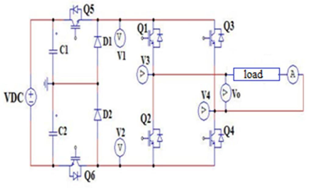
C. Reduced Switches count 5-level H- Bridge Inverter The reduced switches count 5-level h- bridge inverter circuit as shown in fig.5. The circuit consists of six switches (Q1, Q2, Q3, Q4, Q5, Q6) and two diodes (D1,D2). The circuit contains two conversion stages. The first stage produces two-level voltage with devices Q1, Q2 and diodes D1, D2, and the second stage produces three-level voltage with devicesQ1, Q2, Q3 and Q4 in an hbridge model. The primary switching devices (IGBTs) may be switched on or off to provide five -level voltage at the inverter's output. The Inverter output voltage (Vo) is defined by the difference between V3 and V4. Table.3.gives the switching states and voltage levels of the five-level H-bridge inverter reduced switch count.
Fig.5. Reduced Switches Count 5-Level H-bridge Inverter
Advertisement
Table.3. Switching States And Voltage Levels M Main switching devices Voltage levels
Q1 Q2 Q3 Q4 Q5 Q6 V1 V2 V3 V4 Vo 1 on off off on on on Vdc/2 -Vdc/2 Vdc/2 -Vdc/2 Vdc
2 off on on off on on Vdc/2 -Vdc/2 -Vdc/2 Vdc/2 -Vdc
3 on off on off * * 0 0 0 0 0 4 off on off on * * 0 0 0 0 0 5 on off off on on off Vdc/2 0 Vdc/2 0 Vdc/2
6 on off off on off on 0 -Vdc/2 0 -Vdc/2 Vdc/2
7 off on on off on off Vdc/2 0 0 Vdc/2 -Vdc/2
8 off on on off off on 0 -Vdc/2 -Vdc/2 0 -Vdc/2
M= modes and * indicates on or off
For table 3, the mode of operations is eight. There are, In mode 1, the switching devices Q1, Q4, Q5, and Q6 are in an on state. The output voltage Vo = Vdc is generated. In mode 2, the switching devices Q2, Q3, Q5 and Q6 are in an on state, the output voltage Vo = -Vdc is generated, In modes 3 & 4, only two switches i.e., Q1 and Q3 or Q2 and Q4 are in on state. The output voltage, Vo =0, In modes 5 & 6, only 3 switches i.e., Q1, Q4, Q5 or Q2, Q3, Q6 are in an on state, the output voltage Vo=Vdc/2 is generated. In modes 7 and 8, only 3 switches, i.e., Q2, Q3, Q5 or Q1, Q4, Q6 are in an on state. The output voltage Vo = -Vdc/2 is generated [11].
III. CONTROL TECHNIQUES FOR PROPOSED SYSTEM
The control techniques of the proposed system consist of two stages. They are the mppt stage and the modulation stage. For the first stage, the INC MPPT control technique is used, which provides a duty ratio for controlling the DC-DC boost converter and allows the PV cells to operate more efficiently and extract maximum solar energy. In the second stage, the phase-shifted sinusoidal pulse width modulation (PSCPWM) control technique is used to control the gating pulse of the 5-level reduced switch h-bridge inverter.