International Journal for Research in Applied Science & Engineering Technology (IJRASET) ISSN: 2321-9653; IC Value: 45.98; SJ Impact Factor: 7.429 Volume 9 Issue XI Nov 2021- Available at www.ijraset.com For mode 7and 8 has two distinct states, gating logic in state (b) as follows y7b = (-Vdc ≤ Vref ≤ -Vdc/2) ∧ ((Vref > Vc1)∨ (Vref > Vc3)) y8b
= (-Vdc ≤ Vref ≤ Vdc/2)∧((Vref>Vc2)∨ (Vref > Vc4))
For mode 2, gating logics are y2 = (-Vdc≤ Vref≤ -Vdc/2) ∧ ((Vref ≤Vc1) ∧ (Vref ≤ Vc2) ∧ (Vref ≤ Vc3) ∧ (Vref ≤ Vc4)) Based on table 3, Logic circuits for each switch can be given as follows [11] Q1 = y1 ∨ y3a ∨ y3b ∨ y5a ∨ y5b ∨ y6a ∨ y6b Q2 = ¬Q1 Q3 = y2 ∨ y3a ∨ y3b ∨ y7a ∨ y7b ∨ y8a ∨ y8b Q4 = ¬Q3 Q5 = y1 ∨ y2 ∨ y5a ∨ y5b ∨ y7a ∨ y7b Q6 = y1 ∨ y2 ∨ y6a ∨ y6b ∨ y8a ∨ y8b
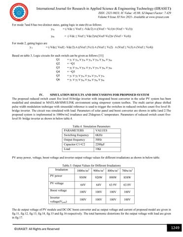
IV. SIMULATION RESULTS AND DISCUSSIONS FOR PROPOSED SYSTEM The proposed reduced switch count five level H-bridge inverter with integrated boost converter in the solar PV system has been modelled and simulated in MATLAB/SIMULINK environment using simpower system toolbox. The multi carrier phase shifted pulse width modulation technique with sinusoidal reference is used to trigger the switches in reduced switches count five level Hbridge inverter. The circuit was simulated with load. Parameters of solar panel and boost converter are shown in table.1and 2.The proposed system is implemented in 1000w/m2 irradiance and 25degrees C temperature. Parameters of reduced switch count fivelevel H- bridge inverter as shown in below table.4. Table.4. Simulation Parameters PARAMETERS VALUES Switching frequency
6KHz
Output frequency
50Hz
Capacitor C1=C2
2200µF
Load
10Ω
PV array power, voltage, boost voltage and inverter output voltage values for different irradiations as shown in below table. Table.5. Output Values for Different Irradiations Irradiation 1000w/m2 900w/m2 800w/m2 700w/m2 PV power PV voltage Boost voltage Inverter voltage(Vpeak)
950W
920W
898W
858W
64V
64V
63.9V
63.8V
100V
100V
100V
100V
100V
100V
100V
100V
The dc output voltage of PV module and DC-DC boost converter and ac output voltage and current of proposed model are given in fig.11, fig.12, fig.13, fig.14, fig.15 and fig.16 respectively. The total harmonic distortions for the output voltage with load are given in fig.17.
©IJRASET: All Rights are Reserved
1249


