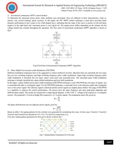
International Journal for Research in Applied Science & Engineering Technology (IJRASET) ISSN: 2321-9653; IC Value: 45.98; SJ Impact Factor: 7.429 Volume 9 Issue XI Nov 2021- Available at www.ijraset.com A. Incremental conductance MPPT control method: To determine the maximum power point, many methods were developed. They are different in their characteristics. Such as, sensors, cost, correct tracking, speed, accuracy. In this paper, the INC MPPT control technique is used and it provides better dynamic performance.in fig.3.,seems to be a bell-shaped curve, indicating that the slope of the curve is positive in the left hand, negative in the right hand, and maximum power is zero (dp/dv=0). The output power differs depending on the climate, but the voltage should stay constant throughout the operation. The flow chart of incremental conductance MPPT algorithm is shown in fig.6.
Fig.6.FlowChart of Incremental Conductance MPPT Algorithm B. Phase Shifted Carrier pulse width Modulation (PSCPWM) Different modulation techniques have to be suggested to control multilevel inverters. Basically there are classified into two types they are low switching frequency and high switching frequency pulse width modulation. Again high switching frequency pulse width modulation is classified into two types: space vector pwm and sinusoidal pwm. The sinusoidal pulse width modulation technique is broadly classified into: phase shifted modulation and level shift modulation. In this paper, a phase shifted carrier pulse width modulation (PSCPWM) technique is used. PSCPWM has two types of signals: one is sinusoidal and other is a triangular signal. For the PSCPWM technique, a sinusoidal wave is the reference signal and a triangular wave is the carrier signal. The reference signal is identical and the carrier signals are slightly phase shifted. The usage of PSCPWM is a capability to improve the control performance. All carriers have the same frequency and same peak-peak amplitude and different phase angles. The results are merged into a single logical diagram. A MLI with ‘L’ voltage levels requires (L-1) triangular carriers. The proposed L=5 levels h-bridge MLI requires (L-1)= 4 carrier signals. The modulation index (M), given by A M= A The phase shift between any two adjacent carrier signals, given by 360 θ= L−1 Based on table 3, the gating patterns for the switches were generated by considering four cases. In four cases, Vcarrier1, Vcarrier2, Vcarrier3 and Vcarrier4 are denoted by Vc1, Vc2, Vc3 and Vc4 respectively [11]. First case: Gating pattern generation for first case is shown in below fig.7
Fig.7. Gating Pattern Generation for First case
©IJRASET: All Rights are Reserved
1247


