
5 minute read
International Journal for Research in Applied Science & Engineering Technology (IJRASET)

from Effective Utilization of Available PEV Battery Capacity for Mitigation of Solar PV Impact
by IJRASET

ISSN: 2321-9653; IC Value: 45.98; SJ Impact Factor: 7.538
Volume 11 Issue III Mar 2023- Available at www.ijraset.com
Advertisement
The PEV charging profile can be switched to a triangular shape by setting KChg-a = 0 5 and KChg-b = 0, as shown in Fig. 2(c); a constant charging profile can be obtained by setting KChg-a = 0 0 and KChg-b = 1 0, as shown in Fig. 2(d). Discharging of the PEV battery is performed for peak load support in the evening when PV power is not available, while retaining a limited capacity in case there is a need for travel. This limited capacity depends on the distance for which the PEV will need to be able to run before the next charging. A peak-shaving strategy is adopted for discharge operation where the PEV battery will inject power depending on the available capacity in the PEV battery. The discharging period can be obtained from a reference demand curve, as shown in Fig. 3(a), derived from historical demand curves of the customer household where the PEV will be plugged in. If discharge operation is performed for TDsch hours using a peak shaving mode, then the following expression will be true: where PImp is the power import from the grid by the load demand, PPS is the threshold power for peak-shaving operation, SoCHH is the SoC at the start of the discharge period, SoCPEV min-spec is the user specified minimum SoC of the PEV battery. The value of PPS that satisfies (4) is used to derive TDsch. To effectively utilize the PEV battery capacity in the discharge operation, the PEV discharge current is controlled in such a way that the highest discharging rate appears during the period of the maximum evening peak load, and lower in the periods before and after that, as shown in Fig. 3(b). At a given kth instant, the discharge current is controlled as
The values of IPEV Dsch-max and ωPEV Dsch are obtained from a similar nonlinear system of equation as given in (2) by replacing the parameters related to the charging operation with the parameters related to the discharging operation. The PEV battery overcharge limit SoCPEV max can be obtained from the manufacturer specified maximum limit. The value of SoCPEV min-spec for a PEV battery will depend on how much energy will have to be retained for the travels before next charging opportunity. In this paper, the value of SoCPEV min-spec is obtained using the distance for which the PEV will need to be able to run before the next charging, as where SoCPEV min is the manufacturer specified minimum SoC, ltravel is the travel length before the next charging including any incidental travel (to hospital, police station, etc.) in km, and FEPEV is the PEV fuel economy in kWh/km. It is worth to consider that utilizing a PEV battery for customer load support using V2G functionality will increase the number of charging/discharging cycles and may impact the battery life.


ISSN: 2321-9653; IC Value: 45.98; SJ Impact Factor: 7.538
Volume 11 Issue III Mar 2023- Available at www.ijraset.com
B. Adjustment of PEV Battery Charging/Discharging Current to Account for Intermittent Events
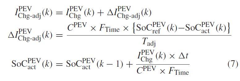
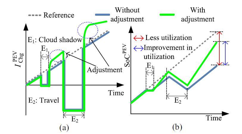
PEV battery will be charged from surplus solar PV power which is practically intermittent due to the dependency on the solar irradiance level. If the solar irradiance is not available for a certain amount of time, the PEV battery cannot be charged. Also, if the PEV is used for any travel within the charging period, the PEV capacity will be depleted. To account for this, the charging rate will have to be adjusted during the periods when surplus PV power is again available. The adjustment of PEV battery charging current is performed based on a reference SoC profile that is obtained using (1). If there is a deviation between the reference SoC and the actual SoC, then adjustment is made to make up for the difference as where IPEV Chg-adj(k) is the adjusted charging rate, _IPEV Chg-adj(k) is the amount of adjustment, and Tadj is a time period for accomplishing the adjustment for minimizing the deviation between the actual SoC, SoCPEV act and the reference SoC, SoCPEV ref . To account for the deviation between the actual SoC and the reference SoC, the PEV charging current may experience high step changes. A rate-limiter is deployed to avoid a high step change in PEV charging current, as. where IPEV Chg-adj-R is the rate limited PEV charging current and nstep is the number of steps to limit the rate. If such an adjustment is made in the charging rate, an effective utilization of the PEV battery capacity can be accomplished. Fig. 4 shows the PEV battery SoC profile that experiences intermittency due to cloud shadow and unavailability of the PEV battery due to an incidental travel. If no adjustment of the charging current is performed, PEV battery capacity is left unused. However, if an appropriate adjustment is carried out using (7), a better utilization of the PEV battery is possible.

ISSN: 2321-9653; IC Value: 45.98; SJ Impact Factor: 7.538
Volume 11 Issue III Mar 2023- Available at www.ijraset.com
Similar adjustments will have to be made for the PEV battery discharge current to account for the deviation between the reference SoC obtained using (5), and the actual SoC. Such deviations can be caused by any incidental travel related capacity discharge, any event requiring a short term high discharge, such as supporting a voltage dip, etc.
C. Control Strategy for PEV Charging/Discharging
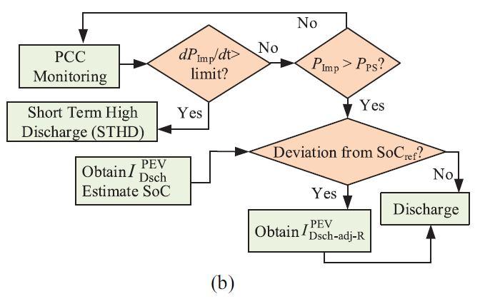
The control flowchart for the proposed strategy is shown in Fig. 5. The PEV management system continuously monitors the PCC net power PPCC. If a reverse power flow at the PCC, greater than a threshold is experienced, the PEV battery is charged with the surplus PV power. However, if a sudden decrease in PV power is found, the PEV battery is put into a short-term discharge (STD) mode and discharged to provide compensation for sudden decrease in PV output, as shown in Fig. 5(a). To account for any deviation between the reference SoC and the actual SoC of the PEV battery, the charging current is adjusted. Such deviations can be caused by a travel causing battery capacity discharge, unavailability of surplus PV power due to cloud shadow, or discharging of PEV battery in STD mode. Charging operation is performed using the adjusted and rate-limited charging current command. PEV discharge operation is performed to provide a peak load support. If the power import from grid, PImp, exceeds the threshold of peak-shaving load, PPS, discharge operation is performed. In case there is an event that causes a sudden increase in PImp, such as a motor start, the PEV battery is put into a short-term high discharge (STHD) mode, as shown in Fig. 5(b). To account for the deviation in SoC created by the difference between the reference demand curve and the actual demand, the STHD operation, and any travel, the discharge rate is adjusted and rate-limited before issuing the discharge command.
III.CASESTUDIES
A distribution network containing medium voltage (MV) and low voltage (LV) feeders has been extracted from a New South Wales distribution system in Australia to investigate the applicability of the proposed mitigation strategy. This is an 80 km long 11 kV rural network containing over 70 11 kV nodes. A single line diagram of the network is shown in Fig. 6. One of the LV feeders is shown in detail in a dashed circular shape.


