9 minute read
Effective Utilization of Available PEV Battery Capacity for Mitigation of Solar PV Impact and Grid Support with Integrated V2G Functionality

from Effective Utilization of Available PEV Battery Capacity for Mitigation of Solar PV Impact
by IJRASET

Mr. Vakeel Sridhar1 , Mr. S Radha Krishna Reddy2
1PG Scholar in the Dept. of Electrical & Electronics Engineering, in Holy Mary Institute of Technology & Science, Bogaram (V), Medchal District, Hyderabad, India
Advertisement
2Professor in the Dept. of Electrical & Electronics Engineering, in Holy Mary Institute of Technology & Science, Bogaram (V), Medchal District, Hyderabad, India
Abstract: Utilizing battery storage devices in plug-in electric vehicles (PEVs) for grid support using vehicle-to-grid (V2G) concept is gaining popularity. With appropriate control strategies, the PEV batteries and associated power electronics can exploited for solar photovoltaic (PV) impact mitigation and grid support. However, as the PEV batteries have limited capacity and the capacity usage is also constrained by transportation requirements, an intelligent strategy is necessary for an effective utilization of the available capacity for V2G applications. In this paper, a strategy for an effective utilization of PEV battery capacity for solar PV impact mitigation and grid support is proposed. A controllable charging/ discharging pattern is developed to optimize the use of the limited PEV battery capacity to mitigate PV impacts, such as voltage rise during midday or to support the evening load peak. To ensure an effective utilization of the available PEV battery capacity when used for travel (which is the main usage of the PEVs) or when interventions in the charging operation is caused by passing clouds, a strategy for dynamic adjustments in PEV charging/discharging rates is proposed. The effectiveness of the proposed strategy is tested using a real distribution system in Australia based on practical PV and PEV data
Keywords: Charging/discharging control, distribution network support, plug-in electric vehicles (PEVs), solar photovoltaic (PV) impact, vehicle-to-grid (V2G).
I. INTRODUCTION
This VEHICLE-TO-GRID (V2G) concept is becoming increasingly attractive for supporting the electric grid [1]–[9] from the stored energy in PEV batteries. PEVs are typically charged from the grid when people come back from work in the evening. Such collective charging can impose an additional burden [10]–[12] on the distribution system. However, with an increasing level of solar photovoltaic (PV) penetration in the distribution networks, this situation could be exploited as an opportunity to support a high level of solar PV penetration. Solar PV resources produce power at the peak level during midday. At this time, the residential feeder demand is typically lower compared to the evening peak. The PV output exceeding the local demand at the point of common coupling (PCC) of the PV inverter has to be injected into the grid and will produce a reverse directional power flow and voltage rise. These issues have been reported in [13] and [14] as major concerns in increasing the PV penetration level. Active power curtailment has been proposed in [15] to limit the voltage rise problem which makes the overall economics of a solar PV installation project less attractive. The consumption of reactive power has been proposed to reduce the voltage rise problem in [16], however, this will create a high reactive power flow and increased power loss in the feeder. Moreover, as distribution networks are constructed using different combinations of overhead and underground cables with high R/X ratio, this method may not be very effective due to the low sensitivity of voltage with reactive power. The integration of storage devices with solar PV systems can be an attractive solution in this case to store the surplus energy from solar PV by charging the batteries. The number of electric vehicles sold each year is increasing due to the variety of types and models brought to market by automobile manufacturers. Although commercial electric vehicles are not designed with comprehensive V2G functionality at the moment, this may be available as an optional feature in near future at extra cost. Studies show that these vehicles are on travel only during a small portion of the day and the rest of the time these vehicles are in parked position [17]. The statistics presented in [18] show that the probability of a PEV to be parked anywhere during the midday period is over 0.9 and the probability for it to be parked at home is over 0.5 for urban and rural weekday or weekend day.
ISSN: 2321-9653; IC Value: 45.98; SJ Impact Factor: 7.538
Volume 11 Issue III Mar 2023- Available at www.ijraset.com
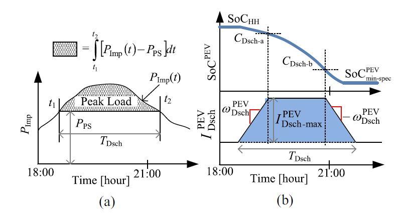
Further, it is likely in the developed countries that there are two cars in a household, one of which may be parked at home most of the time. PEVs can be plugged into the grid using a bidirectional charger while in a parked position to act as a storage device for solar PV systems. Similar with the stationary storage devices used with PV inverters, the PEVs can act to limit the voltage rise problem at midday by consuming power to charge the PEV battery and hence can contribute to the increase of PV penetration level in the distribution grid which would otherwise be limited by the high PV penetration problems. The stored energy in those PEV batteries can support the distribution feeder during evening peak by injecting power to the local PCC so that less power is imported through the feeder to reduce the stress on the grid. However, it is to be noted that the usage of PEV battery for the grid ancillary support can contribute to the loss of its cycle life and may cause a need for an early battery replacement. The effectiveness of the V2G concept for mitigating PV impacts and grid support will depend on how the PEV battery capacity is utilized. The reverse power flow and voltage rise impact of PV will vary mainly depending on the sun irradiance level and the load demand (active and reactive power), and will be at the most severe state in the midday when PV power is at the peak level and load demand is the lowest. Therefore, it would be more effective to charge the PEV battery at the highest rate in the midday and at lower rates before and after the midday as compared to charging with a constant rate all the time. Similarly, it would be wise to discharge the PEV battery at the highest rate during the maximum peak load period and at lower rates before and after. As the PEV battery will have a limited capacity, the charging/discharging rates will have to be such that the capacity is neither left unused nor finished earlier than the intended period of operation. The use of a separate energy storage device for the mitigation of PV and PEV impacts is reported in [19] and [20]. Instead of using a separate battery, PEV battery is used in [21] for mitigation of voltage rise caused by PV. In a previous work, Alam et al. [22] have developed a strategy for the effective usage of the battery capacity integrated with rooftop PV systems for PV impact mitigation and evening peak load support. As the PEV battery capacity is also limited in nature and can also experience intermittencies due to incidental travels, it would be worthwhile to develop a control strategy for effective usage of PEV batteries for PV applications. The contribution of this paper is to develop a wise strategy for charging/discharging of the PEV battery to effectively exploit the opportunities of the V2G concept for mitigating the voltage rise impact of solar PV and for providing the evening peak load support.
The main contributions of the proposed strategy are as follows.
1) To make the PEV batteries consume the highest amount of surplus PV power when the PV impact is most severe.
2) To generate the highest amount of power from the PEV batteries when the maximum demand appear during the evening peak.
3) The dynamic adjustment feature of the PEV charging/discharging currents to account for the interventions in charging/discharging operation caused by travels and passing clouds to ensure an effective utilization of the available battery capacity.
Also, the paper proposes an intelligent strategy for the returning vehicles after work to be charged in the late night/early morning in a controlled manner to coincide the PEV charging load with the customer minimum load so that stress on the distribution system is reduced. Section II of the paper describes the charging/discharging rate determination method using the mathematical formulation of capacity constraints, usage pattern, and charging/ Discharging rate adjustment of the PEV battery. Section III tests the performance of the proposed strategy using a real distribution network model. Section IV concludes the paper summarizing the overall contributions of the paper.
II. PEVBATTERY CONTROLSTRATEGY FORPVIMPACTMITIGATIONANDGRIDSUPPORT
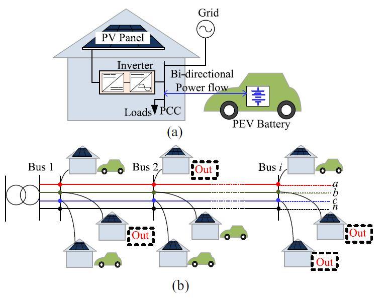
A conceptual diagram showing a parked PEV connected to a PCC of a PV system, household loads and the distribution grid is shown in Fig. 1(a). The surplus power from the PV system will be consumed by the PEV battery to mitigate the impacts of excess PV power, such as reverse power flow, voltage rise, etc. The stored energy in the PEV battery can be used for grid support during grid peak load period, e.g., in the evening, and when no PV is present, e.g., during cloudy period. A number of PEVs connected to the feeder at the same time, as shown in Fig. 1(b), can bring considerable benefits for the whole feeder and upstream network in terms of voltage rise mitigation and voltage support. It is to be noted that at a given instant of time, all the PEVs in a feeder may not be present as they are out for travel as shown using dashed rectangles in Fig. 1(b). This would be the case particularly during the day time. However, the remaining amount of PEVs parked at home can still be used for PV impact mitigation. As PEV battery capacity is limited in nature, a wise strategy to effectively utilize this limited capacity would be necessary for network support. A charging/discharging control strategy leading to an effective utilization of the PEV battery is developed below.
ISSN: 2321-9653; IC Value: 45.98; SJ Impact Factor: 7.538
Volume 11 Issue III Mar 2023- Available at www.ijraset.com
A. Determination of Charging/Discharging Rate for Effective Utilization of PEV Battery Capacity
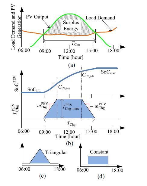
Assume that the PEV will have to be charged in TChg hours during the surplus PV power period over the day, as shown in Fig. 2(a). This period can be determined from the historical load and PV generation profile. The values of the PEV charging current are controlled during this period based on a user-defined pattern to effectively utilize the PEV battery capacity for PV impact mitigation. Typically, under a clear-sky condition, PV output will reach its peak during the midday, increasing from a zero value at the sunrise and again will decrease to a zero value at the sunset. Therefore it would be wise to charge the PEV battery at a higher rate during the midday period as compared to the charging rates during the morning and afternoon periods. Fig. 2(b) shows a trapezoidal pattern is used to consider this scenario in the PEV charging current control. To ensure that the PEV battery capacity is not left unused or the battery is not overcharged, the PEV charging current is controlled at any given time instant k according to
ISSN: 2321-9653; IC Value: 45.98; SJ Impact Factor: 7.538
Volume 11 Issue III Mar 2023- Available at www.ijraset.com
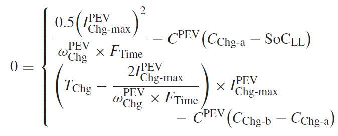
(1) where IPEV Chg is the PEV charging current (ampere); ωPEV Chg is the rate of change of charging current (ampere per time instant) to follow the user defined charging profile; _t is the time difference between two time instants; SoCPEV is the SoC of PEV battery; CChg-a and CChg-b are the two thresholds of SoC (in per unit) specifying the shape of the user defined charging profile. The values of IPEV Chg-max and ωPEV Chg can be determined from a system of nonlinear equations given below in (2), developed based on the geometric relationships of the charging profile during the period TChg in Fig. 2(b). The amount of charge accumulated during the period when the charging rate increases from zero to the maximum value can be obtained using the expression of the area of a triangle. The upper expression in the right hand side of (2) is then obtained by equating this amount with the amount of charge obtained using points CChg-a and SoCLL on the SoC curve in Fig. 2(b). The amount of charge accumulated during the period when the charging rate is constant can be obtained using the expression of the area of a rectangle. The lower expression in the right hand side of (2) is then obtained by equating this amount with the amount of charge obtained using points CChg-a and CChg-b on the SoC curve in Fig. 2(b) where SoCLL is the SoC at the start of the charging operation; CPEV is the capacity of the PEV battery in Ah, FTime is a conversion factor to convert the unit of time to hour from the unit of time used in (1); if the unit of time in (1) is minute or second, FTime will be 60 or 3600, respectively. The limits CChg-a and CChg-b are obtained using user defined parameters KChg-a and KChg-b, respectively, that sets the proportions of the available capacity of the PEV battery to be spent during the time when the charging rate is increasing and when the charging rate is constant, as
The user defined variables KChg-a and KChg-b can be used to control the charging profile patterns. The trapezoidal pattern in Fig. 2(b) is obtained using KChg-a = 0 25 and KChg-b = 0 5.