Design Portfolio
Design Through Construction

I work fluidly across design and building—drawing on framing plans, field experience, and fabrication logic to carry projects from idea to install. I’m excited by studios where designers collaborate with craftspeople, and where details are worked out not just on screen, but in space.


This conceptual office project explores how a bold architectural gesture—a steel lattice “cocoon”—can be grounded by a rational structural system. Designed for a game design studio, it merges public experience (3D scanning atrium) with private office and server spaces. I used Rhino and SketchUp to test a modular plate-and-truss system that balances sculptural ambition with structural clarity.
a hand drawn section cut through the dodedecahedral volume in the center where visitors can be scanned to create virtual avatars.
Exploded envelope axon with labeled systems (InDesign + Rhino).
TOP: Building envelope
MIDDLE: VEIL (modular steel profiles)
BOTTOM: Lateral support structure Hollow Structural Sections (HSS)


Adams Museum Pavilion

Structural Systems 2 Adams Museum
This civic-scale proposal explores a podium-wood typology with layered facade logic. The structural system combines steel, concrete, and timber elements, supporting an envelope of glazing, curtain wall, and insulated panels—designed to meet massing constraints and performance goals.


Modular Framing and Envelope Performance
Passive Housing Prototype
This modular housing prototype responds to cold-climate zones through a fully integrated system of prefabrication and passive design. Each unit balances layout and section height to support cross-ventilation, solar gain, and thermal comfort—validated through WUFI simulation and psychrometric mapping. Two envelope strategies were developed: a CNC-cut WikiHouse frame and a high-performance double-stud wall with VIPs and wood fiberboard, both targeting Passivehaus performance at scale.
Right: Section showing WikiHouse components (top) and Ecocor doublestud wall assembly (bottom)—final iterations of the prototype.
Left:Prefabricated wall module with integrated solar chimney and thermally isolated air channel. Combines wood fiberboard, VIPs, and doublestud framing to balance ventilation, airtightness, and high R-value performance for cold climates.


RIGHT: WUFI simulation output showing moisture behavior and net energy gain under winter and summer conditions.
Isometric views of final 3d model with interior space highlighted and appliances drawn into the modules
Designing these volumes taught me how spatial layout impacts thermal comfort. Each unit balances double- and single-height spaces to optimize airflow, daylighting, and passive strategies like solar gain, sunshading, and wind protection. The psychrometric chart (below) contextualizes these strategies within the human comfort zone.

Open-Frame Learning Space Above Infrastructure
Platform for Making


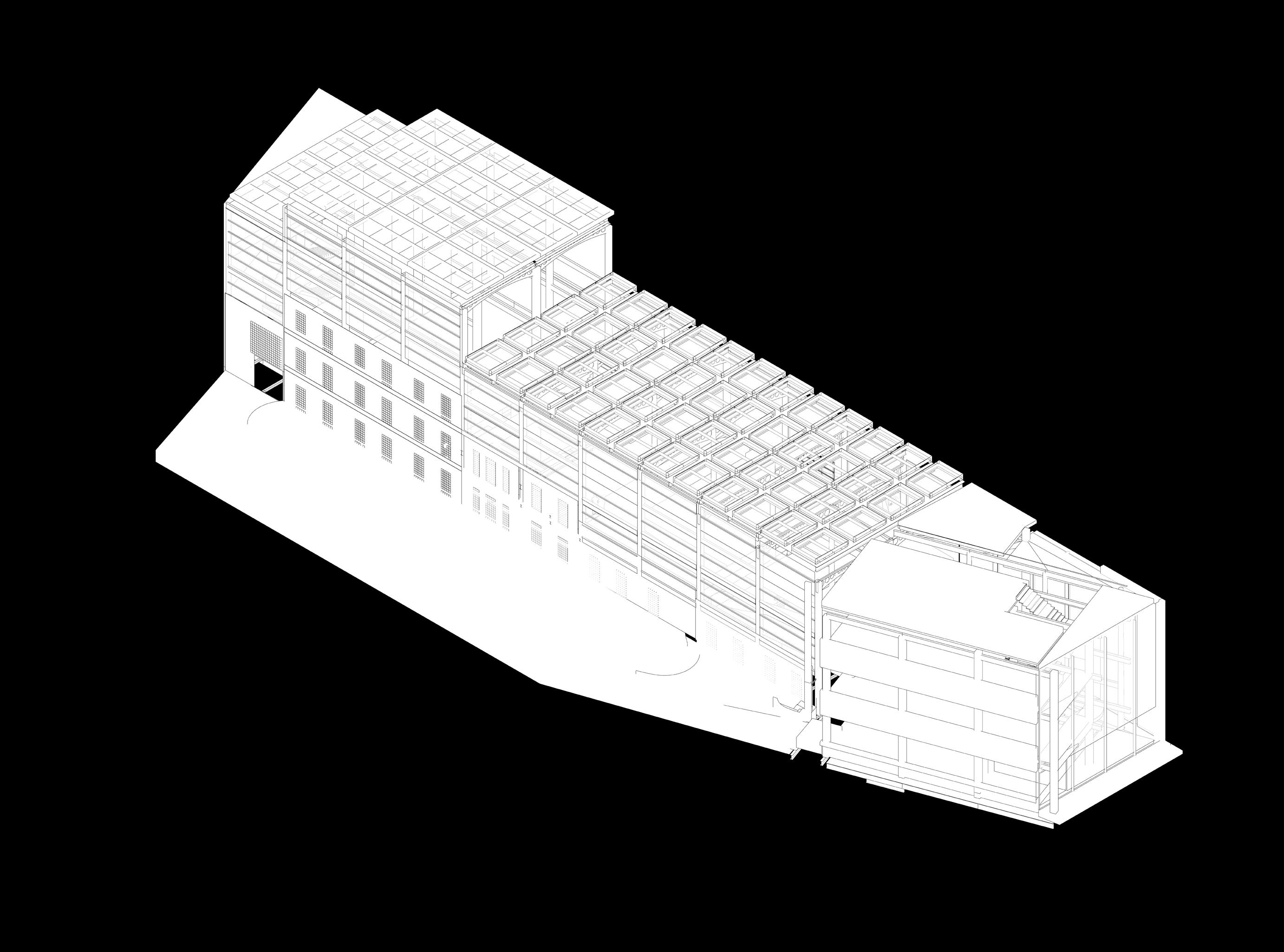
This proposal envisions a collaborative platform suspended above an active rail corridor, integrating a lecture hall, classrooms, and an expansive commons for student work and installation. Layered framing supports the structural span while accommodating light, circulation, and HVAC systems—organized beneath a vaulted skylight to create an open, adaptable learning environment.
BELOW: Detailed wall section showing the assembly of brick veneer, insulated glass block, and curtain wall elements.
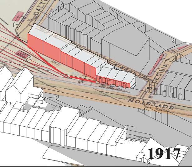
LEFT: Site history diagram tracing development from rail infrastructure in 1852 to present-day massing
BELOW: Floor plan with column grid and HVAC overlay coordinated with the mezzanine layout.


Perspective rendering of commons space below the vaulted skylight with exposed framing.
Integrated Systems: Coordination of HVAC System with main cooling system under first floor

SE ISOMETRIC


Architecture Masters Thesis
Making Ways
This thesis explores how public life can be reintroduced to post-industrial sites through adaptive reuse and spatial thresholds. Set in Holyoke, Massachusetts, the project converts a defunct paper mill into a civic campus—connecting plazas, green space, and new public buildings with timber structures that frame movement and define experience across the site.


THRESHOLD FIVE PLAZA
BETWEEN CAFE AND MILL BUILDING N


THRESHOLD FOUR CANALWALK BETWEEN MILL AND WORKSHOP N


THRESHOLD EIGHT PARK SPACE AND FOLLEY N

Framing, Grading, and On-Site Coordination
From Design to Build
From Design to Build
From Design to Build
From Design to Build with


Drawing from Experience
From Design to Build
This backyard transformation was part of my work with Gilmore Landscape Architecture (GLA), where I supported both design development and field coordination. The project began with a steeply sloped site and a failing porch. I contributed to site documentation, produced five design schemes in SketchUp and CAD, and participated in client meetings. During construction, I worked closely with the GLA team, masons, and carpenters to adapt grading, layout, and sequencing to real-world conditions.
Technical Skills


Left: Sketch overlays and section: Preliminary design studies for wall heights and stair layout.


Technical Skills
Right: Final Site Plan


North-South Section Drawing of Waterfall


Professional Work
Project Management
RIGHT: A decking plan I drew for the carpenters. The detail where the joists meet the posts was laer complicated by the tensioned cable railing BELOW: a recent addition to the design, my drawing for steel workers to manufacture
Once construction began, I focused on resolving deck framing, stair geometry, and custom steel railing details. I developed CAD drawings to guide the carpenters and worked with steel fabricators to specify railing connections over complex stonework. Through this process, I learned how tensioned systems, material tolerances, and trade sequencing affect final construction—and how to improve future documentation by anticipating real-world behavior.
had signed a contract for designservices or building services. In this case I helped to bring this project to our firm (Bidding & Contract Negotiation)and was involved from initial site survey to contract writing and negotiation. Our team moved forward with a set of design concepts that gave the clients a brand new feeling to their outdoor space. I developed the technical dawing for a portch with timber and composite construction and suggested a special design for the stairway down to the patio . Through many iterations that developed from sketches to CAD plans to SketchUp models we worked together to reach the final design which combined aspects of each designers’ ideas. Our mason suggested we use a locally-quarried stone which the clients loved. We built a waterfall for the first

carpenters was to w without While square experience be have they walls diffi the

ius
Field Coordination and Built-in Flexibility
Multi-Phase Construction
ABOVE: a sketch sent from Rob Gilmore to explain a re-design of the plunge pool deck
RIGHT: The crane gently dropiing the concrete shell of the plunge pool from the other side of the hosue
BELOW: The outdoor kitchen and plungepool in progess


Field-marked spray layout overlaid with CAD plan to test pool and deck placement before excavation.
This residential project transformed a steeply sloped backyard into a layered outdoor living space with a plunge pool, custom kitchen, and stone retaining walls. I supported both design development and field coordination, working with the contractor to adapt layout strategies, assist in framing, and troubleshoot fabrication challenges in real time. The scope evolved across phases—each one testing alignment between drawing sets and on-the-ground conditions.
Left: Crane lift staged to overcome limited site access and deliver deck framing and stone units into a constrained backyard.

Middle: Masonry underway around the plunge pool, prior to stone veneer and decking.
Right: Patio stone installation in progress—cut and placed to meet the pool edge with precision.


Left: Rendering of layered deck composition, including furniture, planting, and fence.


Left: Completed installation with integrated pool, kitchen, planting beds, and material transitions.
Above: CAD plan and rendering of outdoor kitchen countertop produced for the stone cutter.

Site Furniture and Fabrication Studies
Carpentry + Joinery
This page highlights a series of design-build furniture and fence projects completed while working with Gilmore Landscape Architecture and as independent commissions. I developed custom concepts for benches, fences, and modular outdoor tables using SketchUp and hand tools. The work bridges conceptual design with fabrication constraints, focusing on joinery, disassembly, and nesting logic—key themes in site carpentry and material-efficient outdoor construction.
Outdoor Furniture Concepts
Outdoor Furniture Concepts


These are my own designs, attempts to show a client their options for a nesting or otherwise-collapsable set tables for gatherings up to 12.
Diagrams I made with Sketchup to illustrate to my team and eventually to the SketchUp diagrams illustrating joinery and assembly methods for collapsible table and bench sets.


Four identical tables inspired by Enzo Mari’s self-build style, designed to seat 4 individually or 12 combined.
Nesting tables offer flexible arrangements for gatherings from 2 to 12, including twin coffee tables.


Right: the simple and elegant option made for picnic-style events


Two completed fence installations, designed and documented inhouse and built under my onsite supervision.


Above: A rendering of a fence design I made with Sketchup

