

AUGIWORLD Education and Training

AUGI Members Reach Higher with Expanded Benefits
AUGI is introducing three new Membership levels that will bring you more benefits than ever before. Each level will bring you more content and expertise to share with fellow members, plus provide an expanded, more interactive website, publication access, and much more!
Basic members have access to:
• Forums
• HotNews (last 12 months)
• AUGIWorld (last 12 months)
DUES: Free
Premier members have access to:
• Forums
• HotNews (last 24 months)
• AUGIWorld (last 24 months)
DUES: $25
Professional members have access to:
• Forums
• HotNews (full access)
• AUGIWorld (full access and in print)
• ADN 2013 Standard Membership Offer
DUES: $100


From the President

AUGI MEMBERS,
It’s been a few weeks since Autodesk University 2025 in Nashville, and what a whirlwind it was!
This year’s AU was especially memorable as I found myself wearing many hats representing AUGI and CAD Manager School as an Autodesk Group Network Leader, serving as an Autodesk Expert Elite, Autodesk Community Volunteer, Global eTraining Ambassador, and even stepping in as an AU Speaker for the CAD Managers Discussion Panel at the last minute.
That panel has always been my #1 session to attend, so going from sitting in the audience last year to
sharing the stage with my fellow panelists this year was an absolute honor. If you were in the audience, I hope I held my own among such an incredible and talented group of CAD leaders.
What I love most about events like AU is the in-person networking connecting with AUGI members, industry friends, and of course, my fellow AUGI Board members. I even managed to wrangle a few of them together for this photo:
If you’ve ever attended an event like this and felt like you were on the outside looking in, here’s my best advice: step out of your comfort zone.
Start small. Talk to the person sitting next to you in class. Ask where they’re from, what they do, or what they hope to get out of the session. It’s an easy icebreaker that often leads to great conversations.

Here’s another tip…when it’s mealtime, grab your food and find a table with just one person sitting there. Pull up a chair, introduce yourself, and see where the conversation goes. And before you part ways, look them up on LinkedIn right then and there, and send that connection request before the post-session rush pulls you away. These little actions can turn conferences into meaningful, long-lasting connections.
Now, there’s something special I’ve been waiting to share here in AUGIWORLD since leaving Nashville, something that’s been tough to keep under wraps especially since I’m pretty active on social media.
During the Design & Make Celebration, I was chatting with a group when Shaun Bryant pointed out that we had four different AUGI Presidents standing together. We all looked around, laughed, and said, “Well, that’s pretty cool!” Naturally, we had to take a photo. From left to right: Me, KaDe King, Richard Binning, and David Harrington.

In that moment, I felt deeply grateful to be serving as your current El Presidente alongside our incredible Board of Directors and Advisory Board members. We stand on the shoulders of those who came before us while paving the way forward with fresh ideas, new member perks, and experiences that keep AUGI thriving as the industry’s most trusted community.
Thank you for walking down memory lane with me and for being part of this incredible journey.
I hope you enjoy this month’s issue, and a big thank you to all the authors and advertisers who make AUGIWORLD possible.
Until next time, Eric
AUGIWORLD
www.augi.com
Editor
Editor-in-Chief
Todd Rogers - todd.rogers@augi.com
Copy Editor
Miranda Anderson - miranda.anderson@augi.com
Layout Editor
Debby Gwaltney - debby.gwaltney@augi.com
Content Managers
3ds Max - Brian Chapman
AutoCAD - Open
AutoCAD Architecture - Melinda Heavrin
BIM/CIM - Stephen Walz
BricsCAD - Craig Swearingen
Civil 3D - Shawn Herring
Electrical - Mark Behrens
Manufacturing - Kristina Youngblut
Revit Architecture - Jonathan Massaro
Revit MEP - Jason Peckovitch
Tech Manager - Mark Kiker
Inside Track - Rina Sahay
Advertising/Reprint Sales
Nancy Tanner - sales@augi.com
AUGI Executive Team
President
Eric DeLeon
Vice-President
Frank Mayfield
Treasurer
Todd Rogers
Secretary Kristina Youngblut
AUGI Board of Directors
Eric DeLeon
Chris Lindner
Frank Mayfield
Todd Rogers
Shelby Smith Scott Wilcox Kristina Youngblut
AUGI Advisory Board of Directors
Gil Cordle
Jason Peckovitch
Rina Sahay Jeff Thomas III
Publication Information
AUGIWORLD magazine is a benefit of specific AUGI membership plans. Direct magazine subscriptions are not available. Please visit www.augi.com/account/register to join or upgrade your membership to receive AUGIWORLD magazine in print. To manage your AUGI membership and address, please visit www.augi. com/account. For all other magazine inquires please contact augiworld@augi.com
Published by:
AUGIWORLD is published by AUGI, Inc. AUGI makes no warranty for the use of its products and assumes no responsibility for any errors which may appear in this publication nor does it make a commitment to update the information contained herein.
AUGIWORLD is Copyright ©2025 AUGI. No information in this magazine may be reproduced without expressed written permission from AUGI.
All registered trademarks and trademarks included in this magazine are held by their respective companies. Every attempt was made to include all trademarks and registered trademarks where indicated by their companies.
AUGIWORLD (San Francisco, Calif.) ISSN 2163-7547

Trials, Tribulations, and Training: Navigating a Career Transition in the AEC Industry
INTRODUCTION
Change is rarely comfortable. After several years serving as a BIM Manager, I now find myself in a position many of us in the AEC industry will face at one point or another: between jobs. The transition is both humbling and eye-opening. It forces you to take a step back from the daily grind of project deadlines and deliverables and instead focus on something far more personal, finding your next opportunity.
The trials of the job search are real: countless applications, interviews that don’t move forward, and postings that seem tailor-made but slip through your fingers. Yet in this in-between space, I’ve also rediscovered the value of education and training. Not just as a means of sharpening technical skills, but as a lifeline for staying relevant, engaged, and mentally resilient during uncertain times.
TRIBULATIONS – THE REALITY OF THE JOB HUNT
Searching for a new position in the AEC industry is not for the faint of heart. The job descriptions often read like wish lists companies want someone who can manage BIM standards, lead coordination, train staff, and code Dynamo scripts, all while stamping drawings. The reality is that no candidate checks every box, yet it’s hard not to second-guess yourself when your skills don’t perfectly align with what’s posted.
There’s also the emotional toll. Applications disappear into the void with no response. Recruiters show initial interest but move on quickly. Some interviews go well, but the offer never comes. Each “almost” is both a learning moment and a reminder of how competitive our industry can be.
And beyond skills, there are the realities of life. As a single father, I need flexibility to take my kids to school, meet them at the bus, and be available when they are with me. Some companies embrace this balance, but others are rigid. In fact, one promising opportunity was rescinded because the organization ultimately couldn’t support a flexible schedule. That experience was discouraging, but it also clarified what I’m looking for: not just a position, but a place where professional excellence and personal responsibilities can coexist.
TRAINING AS A TOOL FOR RELEVANCE
While job hunting can feel like waiting for doors to open, training is something you can actively pursue. Every certification, webinar, or course is a way to sharpen your skills and demonstrate that you’re staying engaged with the industry. Autodesk Certified Professional exams, Dynamo or Python scripting workshops, or deep dives into Autodesk Construction Cloud aren’t just resume boosters, they’re proof that you’re invested in your own growth.
For me, training has also been a way to maintain rhythm and purpose. When you’re not tied to project deadlines, it’s easy to feel disconnected. Learning fills that gap. It keeps your mind sharp, gives you talking points for interviews, and helps you see where the industry is headed. In a rapidly evolving environment AI tools creep into workflows, Forma and ACC updates rolling out constantly, firms experimenting with new project delivery methods staying still isn’t an option.
And training doesn’t have to be formal. Participating in AUGI forums, testing new Revit features, or even setting up small personal projects in tools like Navisworks or Resolve are all forms of education. They’re chances to experiment without the pressure of billable hours.
The truth is, when you can’t yet control where you work, you can still control how much you grow
ACCESS DENIED – TRAINING WITHOUT THE TOOLS
One unexpected obstacle in this transition has been losing access to my Autodesk account. Technically, an Autodesk account is supposed to belong to the user, not the company. I’ve had the same account for over a decade, spanning three different firms. It stored my certifications, tracked my community participation, and gave me access to software, forums, and training resources.
But because of the newer single sign-on (SSO) requirements, my account was locked to the email address of my previous firm. When I was let go, that access disappeared and I could not log in to change my email to a personal one before it was locked down. Autodesk has so far been reluctant to help me regain control. Maybe that will change by the time this article is reached. One could only hope.
*Fingers crossed*
This has created a gap I didn’t anticipate. Without that account, I’ve lost access to certifications I’ve earned, forums I’ve contributed to, and software I could have used to continue training and exploring. It’s not just a matter of convenience; it’s a setback in professional development at a time when training and education matter most.
For those of us between roles, this raises a bigger question about ownership of professional identity. If our careers span firms, but our accounts are tied to employers, what happens when that employment ends? Independent resources like AUGI, community forums, and third-party training become even more vital because they remain accessible no matter where we work.
EDUCATION BEYOND SOFTWARE
Not all education comes in the form of software training or technical certifications. Sometimes the lessons that matter most are the ones learned outside of a classroom or a project model. This job search has been its own kind of training ground one focused on patience, resilience, and adaptability.
I’ve learned to communicate my values more clearly, not just in terms of Revit proficiency or BIM management, but in how I help teams work better together. I’ve had to practice active listening in interviews, tailoring my responses to align with company culture as much as technical needs. These are skills that no tutorial can fully teach, but they are critical to building a sustainable career.
There’s also emotional education. Rejection builds resilience. Networking teaches humility and gratitude. Even setbacks force you to recalibrate what matters most, not just by chasing the next paycheck but seeking an environment where you can thrive both professionally and personally.
In many ways, this has been a reminder that our careers are not defined only by the tools we master, but by the people we become along the way. Technical training sharpens our craft, but life’s trials train our character.
CONCLUSION – TRAINING FOR THE LONG GAME
If there’s one thing this season of transition has reinforced, it’s that education and training are not just about software updates or new certifications, they’re about preparing ourselves for every stage of the journey whether that’s leading a BIM team, navigating a difficult job hunt, or balancing career and family responsibilities.
The trials and tribulations of finding a new role are real, but they also highlight where growth happens. Technical training keeps us sharp. Life lessons build resilience. Together, they shape not just the professional we present on paper, but the person we show up as in the workplace.
For anyone else in the middle of their own “inbetween,” I’ll share this: keep learning, keep growing, and keep your priorities in sight. The right opportunity isn’t just about what you bring to the company but about finding a place that supports who you are beyond the model. In the end, that’s the kind of education and training that lasts a lifetime.

Jason Peckovitch, an AUGI Advisory Board Member, is an Autodesk Revit Certified Professional for Mechanical and Electrical Design located in SE Iowa. He is currently looking for his next company and role. His CAD/BIM career spans over 25 years, and he transitioned to the AEC Industry in 2007 as a Mechanical HVAC Drafter before moving into BIM Management, where he has been working since. Jason is also the father of three children: Shelby (13), Blake (11) and Logan (8), a published photographer, gamer, and car/tech guy. He can be reached at thatbimguy@ gmail.com, found on X under the handle ThatBIMGuy, or connect with him on LinkedIn or several other user platforms like AUGI Community, CAD Manager’s School or BIM Heroes.




List Dealing with the

your workflow, decisions, choices and delivery by being vague, ambiguous, not thought of, overlooked or not fully developed. Here are some that I think can range from annoyances to “full stop” roadblocks and belong on the Un List.
THE UNKNOWN
This is the Un that covers all other Un’s. It really covers all the things on Un list. They are the things that are not fully fleshed out. I covered this in the new tech ambiguity article in June of 2025, so I am not going to spend time on it again. Let it suffice to say that the Unknown impacts you… a lot.
THE UNASSIGNED
This Un can cause delays in workflow that are not discovered until something drops by the wayside. When tasks go unassigned, they don’t get done.
The partner of this Un is assumption that people make that “others” are taking care of it. Running a quick second and third in this partnership of nonproductivity is the concept of “It’s not my job” and “I didn’t know that I was supposed to do that”. When tasks are defined, they must be assigned. Give each one to an individual or specific team in order to get them done. I have been bitten a few times by not specifically tasking someone or some group with doing this or that. Don’t assume someone knows who is working on each task. Assign them explicitly and remind people that they have a task.
THE UNAVAILABLE
Unavailables are those things that you expect to be there as a quick and handy resource, but for many reasons are just not there. It may be a person or equipment or data or whatever. It becomes and Un because it is use by others, broken, misplaced, busy or nonexistent. You thought that when called on it would be around to make your process smooth. There could be delays in access that impact your timeline. Resources that are not there when you need them. At best, you can find a workaround, a fill in, or another tool, but it will slow you down. While these things are sometimes unavoidable (another “un”), they can be minimized by preplanning and reserving resources that will be needed. It takes more thinking and planning, but it can sometimes help.
THE UNSPOKEN
This is a tough one because it impacts you but is not in your control. Others will forget to tell you things or willfully withhold information at times. There will be things that others know and they could have told you, but it just did not come up. So many times, in a movie I am watching, I see plot twists develop because of information that is not provided or is misunderstood and not corrected. In real life, I try to uncover things that are unspoken when I sense that I am not aware of information or situations. Someone may be overly quiet in a meeting. A team member may hint at something but not fully disclose it. Asking “Is there something I am unaware of?” or maybe “Have you told me everything I need to know?” or a simple “Is there anything else?” can uncover hidden info that helps your progress. Unspoken things can open pitfalls and confound good planning. Keep probing for more when you feel hesitancy in people.
THE UNACCEPTABLE
Quality matters and great workmanship should be part of your work ethic. You should be shooting for superior output in all things. This can mean that some work product can be unacceptable. This can be your own work or others. You can hold yourself and others to a higher standard without demeaning the efforts. Nudging people to do their best means that when they have not put in a greater level of effort, you need to call them on it. This includes holding yourself to the best also. When working with others, be gentle and encouraging when asking for improvements in work product. Keep expectations in line with abilities and don’t ask for more than the persons capabilities can achieve, but you can ask for a little more.
THE UNDELIVERED
When others let you down by not providing what you need, when you need it, then you have fallen into the Undelivered part of the Un List. The undelivered parts of your project may move you from “on time” to “offline”. Like all managers, we expect things to be delivered at the agreed upon time. When they are delayed, it causes issues. The way to avoid this is by having consistent team meetings and reiterate due dates and ask for
timeline updates on all tasks on the critical path. Uncover possible delays and address them early. This avoids surprise notifications about slips in schedule. And while I am at it, make sure that you are getting your tasks done on time and are not on someone else’s undelivered list.
THE UNTESTED
When you deploy technology, it should only be after it is fully tested. But there are instances when the testing is not as extensive as it should be. You, as manager, are the person who manages the testing standards. You can set the bar high, but then you have to manage the processes of testing. If you have a team, they may be tempted to take shortcuts and not fully test everything prior to full launch. There should be policies and procedures for testing. It can be streamlined if needed, but each step must be done. I have had many demands for using unvetted software tools by staff that have twinkles in their eyes from vendors demos. I want twinkles too, but only after testing the tools in our environment, at our firm. It must be vetted and proven to work. Then it is full steam ahead.
Next time I will continue my development of the Un List. Until then, keep your eyes open for the “Unseen”.

Mark Kiker has more than 30 years of hands-on experience with technology. He is fully versed in every area of management from deployment planning, installation, and configuration to training and strategic planning. As an internationally known speaker and writer, he is a returning speaker at Autodesk University since 1996. Mark has served as Draftsman, Principal Designer, CAD/ BIM Manager, IT Director, CTO and CIO. He can be reached at mark.kiker@ augi.com and would love to hear your questions, comments, perspectives and suggestions for topics to cover.

Object Linking & Embedding
Object Linking and Embedding (OLE) is a feature that allows you to copy or move information from one application to another while you retain the ability to edit the information in the original application. Basically, OLE combines data from different applications into one document. For example, you can create an AutoCAD Architecture drawing that contains all or part of a Microsoft Excel spreadsheet.
OLE is a great way to use information from one application in another application, which can be useful for presentations, etc. To use OLE, you need both source and destination applications that support OLE. Information from one document into another document can be inserted by either linking or embedding the information. Both linked and embedded OLE objects can be edited from within the destination application. However, linking and embedding store information differently so it is important to ensure that you are using the correct option for the situation. The relationship between embedding and linking is similar to that between inserting a block and creating an external reference.
An embedded OLE object is a copy of information from another document. When you embed objects, there is no link to the source document and any changes made to the source document are not reflected in destination documents. Embed objects if you want to be able to use the application that created them for editing, but you do not want the OLE object to be updated when you edit
information in the source document. A linked object is a reference to information in another document. Link objects when you want to use the same information in more than one document. Then, if you change the original information, you need to update only the links in order to update the document containing the OLE objects. You can also set links to be updated automatically. When you link a drawing, you need to maintain access to the source application and the linked document. If you rename or move either of them, you may need to reestablish the link.
Let’s look further into using OLE objects with AutoCAD Architecture. We will use Microsoft Excel as an example.
IMPORTING OLE OBJECTS
You can use one of the following methods to insert information from Excel as an OLE object:
Cut or copy information from an existing Excel file and then paste it into the ACA drawing
• Import an existing Excel file
• Open Excel from within the ACA drawing by double-clicking on it and creating the information that you want to use
When the Excel information is inserted into your ACA drawing, you will need to specify an insertion point. By default, the OLE object is displayed with a
frame that is not plotted. OLE objects are opaque, and they will plot as opaque. This means that they hide objects behind them. OLE objects are supportive of draw order. The display of OLE objects can be controlled in one of two ways:
• Set the OLEHIDE system variable to either display or suppress the display of all OLE objects within paper space, model space or both
• Freeze or turn off a layer to suppress the display of OLE objects on that layer
When OLE objects with text are printed, the text size is approximated by the test size in the source application, Excel. It is important to note that OLE objects in ACA drawings are not displayed or plotted in external references or block references.
EMBED OLE OBJECTS
An embedded OLE object is simply a copy of information from another document. For example, a copy of an Excel spreadsheet in AutoCAD Architecture. When you embed objects, any changes made to the source document are not
AutoCAD Architecture 2026
reflected in destination documents because there is no link to the source document. You should embed objects only if you want to be able to use the application that created them for editing, but you do not want the OLE object to be updated when you edit information in the source document.
To embed an OLE object in a drawing, open the document you wish to embed, select, right-click and copy the information. Next open your ACA drawing, right-click and paste the information.
Another way to do this is to open AutoCAD Architecture and enter the command INSERTOBJ. This will bring up the Insert Object dialog box. Next select Create New. Under Object Type, select an application and click OK (see Figure 1), which will open Excel (or whichever application you choose). Now create the information you wish to insert and save the document. In Excel’s File menu, select Exit and Return. Close Excel and the object is now embedded in the AutoCAD Architecture drawing.
If needed, you can adjust the text size. To do this, select the OLE object, right-click, select OLE and then select Text Size. This opens the OLE Text Size
AutoCAD Architecture 2026
dialog box. Now you can select a font, point size and text height. When finished, click OK.
LINK OLE OBJECTS
A linked OLE object is simply a reference to information that is located in another document. Link objects when you want to use the same information in more than one document. If you change the original information, you only need to update the links in order to update the document that contains the OLE objects. Links can be set to update automatically. It is important to note that when you link a drawing, you need to maintain
access to both the source application and the linked document. If you rename or move either of them, you may need to reestablish the link.
To link a file as an OLE object, enter the command INSERTOBJ. This will bring up the Insert Object dialog box. Select Create from File (see Figure 2). Next browse and find the file you wish to use. Click Link and then select OK. Now you will need to select where you wish the OLE object to appear.
To link part of a file as an OLE object in a drawing, begin by opening ACA and Excel. Select the information in Excel you want to link and copy it to the Clipboard. In ACA, click the Home tab on the ribbon, Clipboard panel, paste drop-down and then Paste Special. In the Paste Special dialog box, click Paste Link. Paste Link pastes the contents of the Clipboard into the current drawing and also creates a link to the file in the source application. If you click Paste, the Clipboard contents are embedded instead of linked, so it is important to select Paste Special. In the “As” box, select the data format you want to use and click OK.
EXPORTING OLE OBJECTS
You can link or embed a view of an AutoCAD Architecture drawing within another application that supports OLE, such as Excel. The COPYLINK command copies the view in the current ACA viewport to the Clipboard, and you can then paste the view into the destination document. If you paste an unnamed view into a document, it is assigned a view name such as OLE1. Then, if you exit the drawing, you will be prompted to save your changes to the newly named view. In order to establish the link and to save the view name, OLE1, you must save the drawing.
You can select objects and embed them in documents created by other applications. Embedding will place a copy of the selected objects within the destination document. If you use AutoCAD Architecture to edit the OLE object from within the destination document, the object is not updated in the original drawing.
To embed objects in another document, begin by opening AutoCAD Architecture and selecting the objects that you wish to embed, right-click and select Copy. The selected objects are now copied to the Clipboard. Open Excel and open a new or existing document. Paste the clipboard contents
onto the spreadsheet, following the instructions for embedding the Clipboard contents given by Excel.
To link a view to another document, begin by opening AutoCAD Architecture and save the drawing that you want to link, so that it has a drawing name. If multiple viewports are displayed, you will need to select a viewport. Next, enter COPYLINK at the command prompt. Then open a new or existing document in Excel. Paste the clipboard contents into the document, following Excel’s procedures for inserting linked data (see Figure 3). The inserted OLE object is displayed in the document and can be edited from AutoCAD Architecture through Excel.
EDITING OLE OBJECTS
Linked or embedded OLE objects can be edited in a drawing by double-clicking the object to open the source application. You can use any selection method to select OLE objects and then you can use most editing commands, the Properties palette or grips to make changes. When grips are used to change the size of an OLE object, the shape of the object does not change as long as the aspect ratio is locked in the Properties palette. If you have resized an OLE object and wish to restore it to its original size, select the OLE object, right-click and select OLE Reset. It is important to note that the following editing commands are not available
AutoCAD Architecture 2026
for OLE objects: BREAK, CHAMFER, FILLET and LENGTHEN.
Before looking at how to edit OLE objects, it is important to understand the difference between editing a linked object versus an embedded object. The document that contains a linked drawing stores the drawing’s file location. You can edit a linked drawing either from the destination application or in the source program. The program must be loaded or accessible on the system along with the document you are editing. An ACA drawing that is embedded within a document can be edited only from within the destination application. You will need to double-click the OLE object to start the program. Editing the original drawing in the program has no effect on documents in which that drawing is embedded.
To edit a linked ACA drawing from within the destination application, begin by opening the document that contains the linked drawing (for example, a Microsoft Excel file). Double-click the linked drawing and the drawing will open. You can also select the OLE object, right-click and select AutoCAD Drawing Object, and then Edit (see Figure 4). Next modify the drawing as necessary and click the File menu and select Save when done. To return to Excel, click the File menu and hit Exit. The drawing is now changed in all documents that have links to it.
Figure 3 – Copylink Drawing in Excel
Figure 4 – Edit OLE Object
AutoCAD Architecture 2026
To edit a linked drawing in the source application, begin by starting the program and opening the linked drawing. Make modifications to the drawing and view as necessary. Save the changes when finished. Update the link in the destination document if necessary. The drawing is changed in all documents that have links to it.
To edit embedded objects, begin by opening the Excel document that contains the embedded AutoCAD Architecture objects. Double-click the embedded objects to start the ACA program and display the objects and modify them as necessary. Save changes to the embedded objects by clicking the File menu and selecting Update. Now return to the destination application by clicking the File menu and selecting Exit.
To control the display of OLE objects in AutoCAD Architecture, enter the command OLEHIDE. Now enter one of the following values:
0 – Displays OLE objects in both paper space and model space
1 – Displays OLE objects in paper space only
2 – Displays OLE objects in model space only
3 – Does not display OLE objects
You can also control the display of the OLE frame within a drawing. To do this, enter OLEFRAME at the command prompt. Then enter one of the following values:
0 – Frame is not displayed and is not plotted
1 – Frame is displayed and is plotted
2 – Frame is displayed but is not plotted.
CONTROLLING PLOT QUALITY
When a raster plotter is used, OLE objects are treated as raster objects. Since large, highresolution, color-rich rasters can be expensive to plot, the OLEQUALITY system variable can be set to control how each OLE object is plotted. The default setting is Automatically Select, and it assigns a plotquality level based on the type of object. The higher the plot-quality setting, the more time and memory are used to plot.
The Plotter Configuration Editor can also be used to adjust OLE plot quality. The Graphics option
displays a Raster Graphics dialog box with a slider that controls OLE plot quality. It is important to note that nested OLE objects may cause problems. For example, an OLE object that is not in the current view plane is not plotted, but the frame is plotted based on the setting of the OLEFRAME system variable.
To set the plot quality for OLE objects, begin by clicking the Tools menu and selecting Options. In the Options dialog box, select the Plot and Publish tab and then in the OLE Plot Quality list, select one of the following settings (see Figure 5):
• Monochrome – For text spreadsheets
• Low Graphics – For color text and pie charts
• High Graphics – For photographs
• Automatically Select – Plot-quality setting assigned based on the type of file
Click Apply to continue setting options or click OK to close the dialog box if you are finished.

Melinda Heavrin is a CAD Coordinator & Facility Planner in Louisville, Kentucky. She has been using AutoCAD Architecture since release 2000. Melinda can be reached for comments and questions at melinda.heavrin@ nortonhealthcare.org
Figure 5 – OLE Plot Quality






Incorporation of Waste Glass Powder (WGP) in Concrete
The integration of waste glass powder (WGP) into concrete presents a sustainable and innovative approach to enhancing concrete performance while addressing environmental concerns. WGP, when processed into a fine powder—typically with particle sizes under 75–100 micrometers—acts as a supplementary cementitious material (SCM) or a partial replacement for fine aggregates. In its finely ground form, WGP exhibits pozzolanic behavior, meaning it reacts chemically with calcium hydroxide (a byproduct of cement hydration) to form additional calcium silicate hydrate (C-S-H), the primary binder in concrete. This reaction not only strengthens the matrix but also improves overall durability.
KEY BENEFITS OF USING WGP IN CONCRETE
Environmental Sustainability
• Utilizes recycled glass, thereby reducing the volume of glass waste sent to landfills.
• Lowers carbon emissions associated with Portland cement production by partially replacing it with WGP.
Enhanced Mechanical Properties
• Contributes to higher compressive and tensile strength through secondary hydration reactions.
• Reduces permeability, improving resistance to cracking and long-term degradation.
Improved Durability
Enhance resistance to chloride ingress, sulfate attack, and alkali-related deterioration.
• Reduces potential for steel reinforcement corrosion, extending the service life of structures.
Better Workability and Finish ability
• Finely ground glass particles can improve the rheology of fresh concrete, making it easier to mix, place, and finish.
Technical Design and Application
• Can reduce bleeding and segregation, improving surface quality.
CHALLENGES AND CONSIDERATIONS
Particle Fineness Requirement
• To achieve optimal pozzolanic reactivity, the glass powder must be ground to below 75–100 µm. Coarser particles may act as inert fillers, diminishing benefits.
Alkali-Silica Reaction (ASR) Risk
• Improperly proportioned mixtures may lead to ASR, a harmful expansion phenomenon. Careful mix design and the use of low-alkali cement or supplementary materials (e.g., fly ash) are essential to mitigate this risk.
Variation in Setting Time and Workability
• Depending on the dosage and type of base cement, WGP can either accelerate or retard setting time. Adjustments to admixture use may be needed.
Quality Control and Consistency
• The chemical composition, color, and particle size of waste glass can vary significantly, necessitating robust quality control measures during processing and batching.
PRACTICAL APPLICATIONS OF WGP IN CONCRETE
Partial Cement Replacement
• WGP can replace 10–30% of Portland cement in concrete mixtures, improving sustainability without compromising structural performance.
Fine Aggregate Substitution
• Ground glass powder can serve as a partial substitute for natural sand, reducing the demand on natural aggregate sources.
Pervious and Eco-Concretes
• In permeable pavement systems and green infrastructure, WGP enhances the strength and environmental performance of pervious concrete mixtures.

Ali Al-Azzawi, P.E., ENV SP Civil Engineer | Site Development & Structural Systems Specialist | Educator
Ali Al-Azzawi is a licensed civil engineer specializing in site development, civil and site design, and the integration of structural systems for a wide range of projects. His diverse project experience spans municipal, commercial, educational, and transit sectors, where he delivers comprehensive solutions in site layout, grading, earthwork, and infrastructure design. Ali is particularly skilled in erosion control strategies and advanced stormwater management, including both static and dynamic modeling approaches.
In addition to his engineering practice, Ali is an active educator, teaching courses in Revit, Civil 3D, and construction management at Houston Community College. He brings realworld design and project management expertise into the classroom, preparing students for careers in the built environment.
Ali earned a Master of Science in Structural Engineering from the University of Houston, a Master of Science in Project Management from DeVry University, and a Bachelor of Science in Civil Engineering from Mustansriah University. He is a Licensed Professional Engineer in Texas and an Envision Sustainability Professional (ENV SP), demonstrating his dedication to delivering resilient, sustainable site and structural design solutions.

The Secret History of AutoCAD’s 7 Named Colors
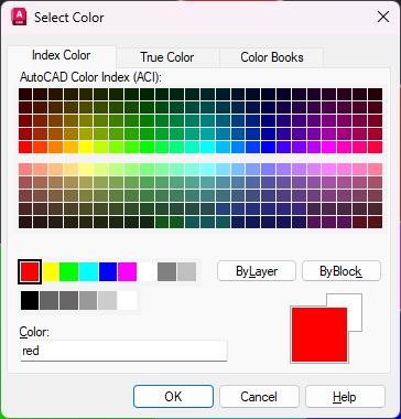
You’re probably more than familiar with AutoCAD’s 7 named index colors and the 256 ACI (AutoCAD Color Index) colors. But have you ever wondered where these colors came from, and why they were chosen? Keep reading to find out!
WHY DOES AUTOCAD HAVE 0-255 INDEX COLORS?
There are 256 colors (zero also counts as a color) because 256 perfectly fits into 1 byte of data.
Back when AutoCAD was first released in December 1982, every byte counted. AutoCAD 1 was written on floppy disks. A floppy disk could hold just
160 KB of data. To put that in perspective, a modern mid-range laptop has a 1TB hard drive, equivalent to about 6,710,886 floppy disks!
HOW DO 256 ACI COLORS FIT INTO 1 BYTE OF DATA?
It’s actually very simple, even for those of us that aren’t computer programmers.
A byte is made up of 8 bits. Think of a “bit” as a choice of either a zero or a one (binary code).
00000000 = 0 = ByBlock
00000001 = 1 = Red
00000010 = 2 = Yellow
00000011 = 3 = Green
11111111 = 255 = White
With 8 bits, you can have 256 possible combinations of zero or one. Each index color is assigned to a unique combination of zeros or ones, making 256 colors. This fits perfectly into 1 byte, an efficient and clever optimization of code.
WHY DOES AUTOCAD HAVE A SET OF 7 NAMED INDEX COLORS?
AutoCAD has 7 named colors: Red, Yellow, Green, Cyan, Blue, Magenta, and White/Black. It limited these for two reasons:
1. Printing/plotting equipment of the time
2. Computer and display limitations.
PRINTING PROCESSES
At the time pen plotters were typically used instead of printers. Pen plotters don’t print dots like a printer, but draw “plotted” vectors, a sort of computer-driven technical drafting robot. Pen plotters mostly had 4 pens of different colors, although some went to 8 pens. The pens were typically black, red, blue, and green by default, with some also using cyan, magenta, and yellow.
AutoCAD 1.0 was released without colors. Instead, it had 127 numbers, and these were mapped to a pen color and plot style on a pen plotter, common at the time. Amazingly, AutoCAD still supports. cdp (ColorDependent Plot Style) Tables
EARLY DISPLAYS
AutoCAD’s developers were also limited by the displays of the time. In the early 1980s, most screens were still monochromatic (often green), with extremely limited pixel control. Those that did have color had a shockingly limited color palette.
AutoCAD version 1 was built for the IBM PC and CP/M. An IBM PC came with a green, monochrome screen. The color screen option wasn’t available until March 1983, and this still displayed only 4 colors with a resolution of just 320px × 200px at about 29–31 PPI (Pixels Per Inch). To put that into perspective, a midrange smartphone today is typically about 2400 × 1080 pixels and 400 PPI, so there are more pixels in a square inch of your phone (1 inch = 25.4 mm) than in the whole of a “color” IBM screen.
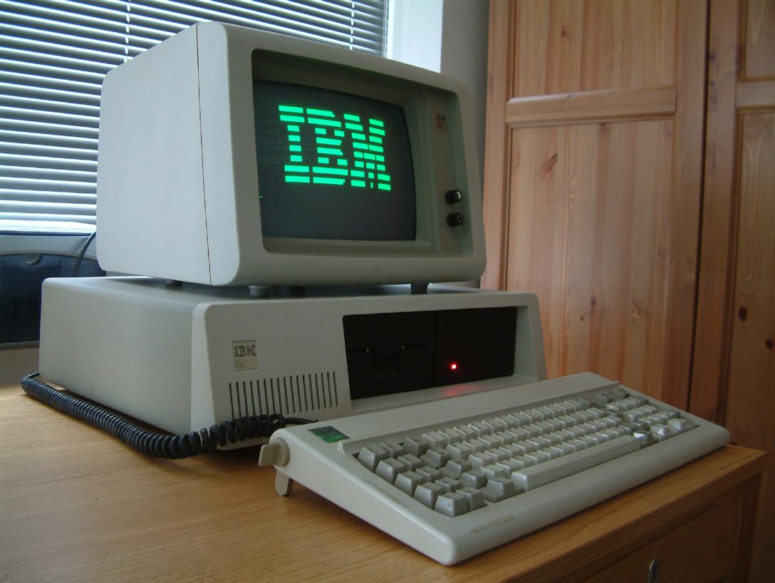
- By Ruben de Rijcke - http://dendmedia.com/vintage/ - Own work, CC BY 3.0, https://commons.wikimedia.org/w/index. php?curid=3610862 ]
When the AutoCAD values were given display colors, sometime in the mid-80s, the colors were picked for maximum contrast and visibility.
Even after colors were introduced to AutoCAD, many users continued to work on monochrome screens. That meant that, when users eventually moved to colored screens, often in the 90s, there were a few surprises when they saw what their drawings actually looked like in color. It has also made it hard to identify the exact point that color was introduced to AutoCAD. If anyone knows, I’d love to hear from them.
DID AUTOCAD NAMED INDEX COLORS INFLUENCE THE AEC AND OTHER INDUSTRY STANDARDS?
Many claim that AutoCAD’s 7 Named Index colors directly contributed to industry standardization of colors, for example, green as a dimension layer.
However, the cause and effect are less clear. AutoCAD was not the first to use the standard named colors of Red, Yellow, Green, Cyan, Blue, Magenta, White, and Black. These colors came from those used by the pen plotters of the time and were chosen for their high contrast. It was also common practice for programmers at the time to limit color to a similar palette in software and games.
AutoCAD
WHAT ABOUT AUTOCAD COLOR 256BYLAYER?
AutoCAD introduced color code 256 (ByLayer) later, because they didn’t want to break backward compatibility.
WHAT IS AN AUTOCAD TRUE COLOR?
As most of us will remember from school science lessons, red, green, and blue (RGB, not RBG) are the primary colors of light. In the “True Color” system, each of these colors has its own 8-bit value, giving 256 possible intensity levels for each color red, green, and blue.
256 (Red) × 256 (Green) × 256 (Blue) = 16,777,216 (Shades)
Some Examples:
0,0,0 = Black
255,0,0 = Red
0,255,0 = Green
0,0,255 = Blue
255,255,255 = White
While the original AutoCAD ran on an 8-bit color system, modern computers can easily handle a 24-bit RGB color definition. That’s over 16 million colors, yet the human eye can only perceive around 10 million.
HSL COLOR
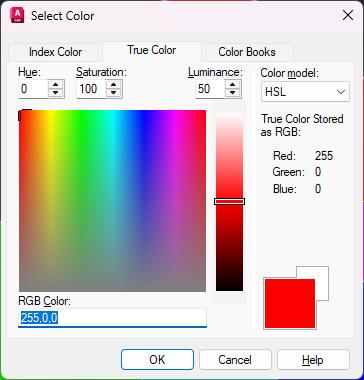
You’ll also notice that in the AutoCAD color dialog, the True Color tab gives you the option to switch between HSL (Hue, Saturation, and Luminance) and RGB mode. This is a way of displaying colors in a more human-understandable way. Note that on the right-hand side of the dialog, the RGB values are displayed anyway.
• Hue: the color, with a value from 0–360 (a circle).
• Saturation: the intensity of the color, 0% (washed out) to 100% (very bright).
• Luminance: how dark or light the color is, 0% (black) to 100% (white).
HOW DOES AUTOCAD TRUE COLOR RELATE TO PRINT AND WEB?
There are many ways of representing color. For different mediums, you need a different color code
system. Some of the main color systems you’ll come across are CMYK (Cyan, Magenta, Yellow, and blacK), Hex Codes, Pantones and RAL.
CMYK COLOR
CMYK stands for Cyan, Magenta, Yellow, and blacK. It’s used primarily in the print industry. That’s because it maps nicely to the 4 different colors used by laser and inkjet printers. A printer combines several colored dots to create almost any shade.
The intensity of each of the four colors is measured as a % (0–100). Theoretically, there are 4,294,967,296 possible color combinations; however, due to restrictions in printer technologies, there are far fewer in practice.
HEX OR RGB COLOR
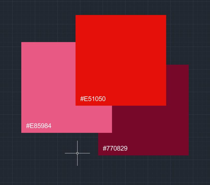
You’re probably familiar with color values that look like this:
#FFFFFF - White
#FF0000 - Red
#00FF00 - Green
#0000FF - Blue
#000000 - Black
These are known as Hex codes or RGB values. Essentially, they are exactly the same as AutoCAD True colors: each of the 3 light colors has 256 possible intensity levels. The only difference is the way they are written down. Using a system of letters and numbers makes it easier for programmers to read the code.
AUTOCAD COLOR BOOKS
A color book ensures consistent results AutoCAD comes preinstalled with some RAL and Pantone color books as standard, but it’s possible to create your own, saved as an .acb file. format. When required, a company will distribute a color book to all of its contractors.
PANTONE COLOR
The Pantone Matching System (PMS) is mostly used by the graphics industry. The system helps to ensure that color is consistent across a variety of applications, from fabric to paint, premixed printer ink to plastic. These values ensure that brands can produce things that are the same color, whether it’s a graphical print or the fabric of a shoelace.
“The appearance of color can change based on the material on which it is produced. In fact, some colors are not achievable at all on a certain material. Having two systems helps to ensure that the colors included are achievable and reproducible based on the materials used.”pantone.com
RALCOLOR
RAL is a German system similar to Pantone, but more

Jacobolus, CC BY-SA 3.0 <https://creativecommons.org/licenses/ by-sa/3.0>, via Wikimedia Commons]
limited (only 213 colors in the classic library). The RAL system is used for architecture, construction, engineering, manufacturing, and fleet vehicles. Each color has a name and code combination, something like “RAL 010 60 35 Rose Red”.
WHY TWO COLORS MIGHT NOT MATCH
Even after all of this, colors do not always match perfectly. Variations in screens, for example OLED vs LED, subtle variation in surface texture, weight and quality of the paper, exact calibration of the printer, and even the time of day, can affect how we see a color.
CIEL*A*B*
The CIELAB color system, sometimes written as just “LAB” color, was created by the International Commission on Illumination. Yep, that really is a thing! It’s a step above RAL and Pantone and is an attempt at a mathematical way of describing how the human eye sees color. It does this by plotting color as a theoretical 3D mathematical model.
• L*: Lightness
• a*: Red vs Green Value
• b*: Blue vs Yellow Value
WRAPPING UP THE COLOR MYSTERIES OF AUTOCAD
In the 40-plus years since the 256 ACI colors and 7 named colors were introduced; we’ve come a long way. From monochrome monitors, pen plotters, and 160 KB floppy disks to OLED screens, in-browser DWG viewers, and 1TB hard drives. But even with over 16,000,000 possible colors now available to us, most CAD drafters only need 7: red, yellow, green, cyan, blue, pink… erm I mean “magenta”, and black/white.

Rose Barfield a.k.a. ‘The Felt Tip Faerie’, is a freelance CAD Expert with a passion for technology and engineering. She enjoys solving complex problems, research and tutoring others. Her work spans projects in drafting, design, and technical support, and she values the opportunity to connect with her fellow CAD nerds.
Buttons Fun
Facts Galore Dialog
THE BUTTON BEGINS
I’ll start by going back to the beginning with the history behind the button. Apparently, thousands of years before Christ buttons were described as physical small knob like objects in nature. They were then eventually introduced into the home as decorative ornaments. Next, these similar shaped objects transitioned onto clothing as fasteners. Then, the idea of the button made its way onto various devices like a washing machine or a TV’s remote control. When a button is pressed on these devices, a particular operation would be executed like turning something on or off. Finally, when the digital world exploded onto the scene, many software applications implemented the idea of the button to help with user input. Likewise, when AutoCAD introduced dialog boxes, four distinct button types are offered to assist the user in making selection choices graphically on the screen.
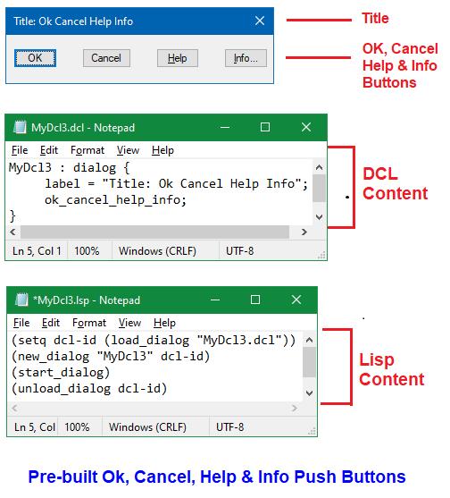
Figure 1
1. THE PUSH BUTTON
The “Push” button is the first and most standard button type offered. This type of button can be seen in dialog boxes that implement AutoCAD’s pre-built Ok, Cancel, Help and Info Push buttons. These were discussed in my first Dialog Fun Facts article back in January of 2024 (see Figure 1).
The Push button usually has the following features:
1. Displays a text label to inform the user the operation that would take place when the button is pushed or selected
2. As a form of visual effect when set focused on the button’s appearance changes with a heavy outline (Figure 1 shows this effect with the OK button)
3. When this button type is pressed, typically only a single operation is executed
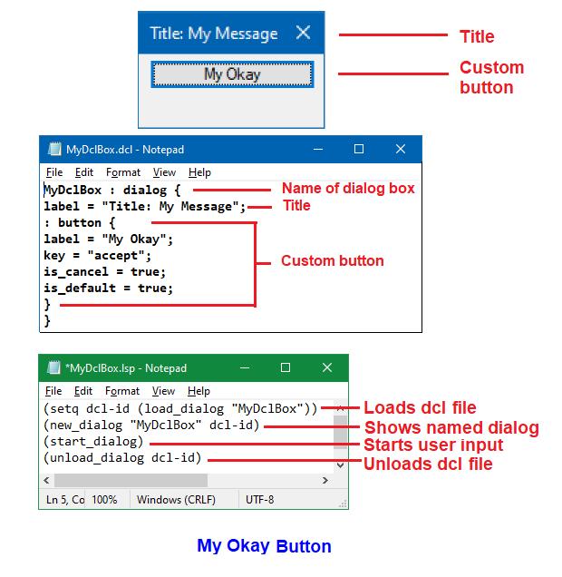
In addition to using AutoCAD’s pre-built dialog definitions, this button type can be generated using a simple dialog definition called out as: button. An example of a customized Push button is again illustrated in my original Dialog Fun Facts article where I show My Okay button (see Figure 2).
Also as discussed in my most recent Dialog Fun Facts - Get Ready, Set, Action article in September of 2024, the Push button can be disabled from selection with the mode_tile function.
A BRIEF BUTTON BREAK
So far this has been all reviewed and nothing new has been presented. But before continuing, to make the loading of Dialog Control Language (dcl) and AutoLISP (lsp) files easier as you follow along with
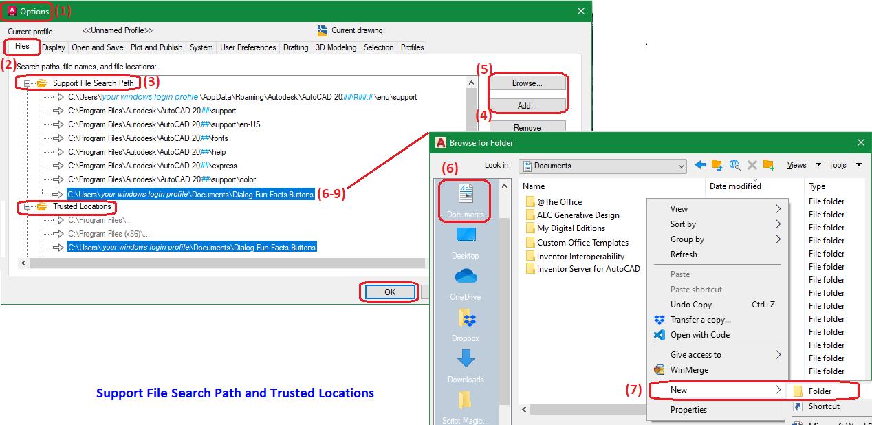
Figure 2
Figure 3
AutoCAD
the remainder of the article, perform the following operations in AutoCAD:
1. At the command prompt enter command Options
2. Click the Files tab
3. Select Support File Search Path
4. Click Add button
5. Click Browse button
6. Select Documents
7. Right mouse click in the blank space inside the folder list and on the menu that appears select New>Folder
8. Enter the following for the folder name: Dialog Fun Facts Buttons
9. Click Open
Next, repeat the same steps from 4 to 9 but this time under Trusted Locations and then click OK
This will complete the process by adding under Documents a new folder called Dialog Fun Facts Buttons into AutoCAD’s Support File Search Path and Trusted Locations (see Figure 3).
For the remainder of the article, all dcl and lsp files generated should be saved under this folder location. AutoCAD can then easily locate both file type extensions to load and execute. Now it’s time to continue with the play-by-play or perhaps it’s more fitting to say button-by-button on the remaining three button types.
2. THE TOGGLE BUTTON
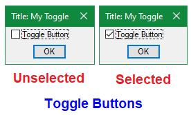
The “Toggle” button is the second type of button dcl supports. This is typically displayed as an empty square box “ n ” with the option of a text label positioned to the right. The user is given the option to select this button and a check mark appears inside the square box “ n ”. When the user selects this again, the check mark will now be cleared and once again only the empty square box remains. Unlike the Push button the Toggle button offers a dual role response operation: Unselected vs Selected (see Figure 4). ✓
4
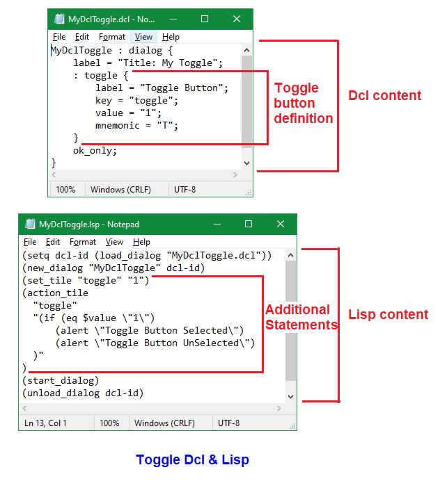
The dcl code needed to generate this type of button is as follows:
Open Windows Notepad application
Enter the code exactly as shown under Dcl content (see Figure 5)
Save the file into folder Documents\Dialog Fun Facts Buttons with the filename: MyDclToggle.dcl
5
In this example, the Toggle button custom dialog box’s name is called MyDclToggle (this is case sensitive). The second line is the label or text that is displayed on the dialog box title bar. The next six lines contain the definition of this button type which starts off with the call out as: toggle. Then the dcl file ends with a reference declaring the use of the pre-built ok_only tile.
Figure
Figure
Like the Push button, the Toggle button can have a label attribute (though not required). The key = “toggle” (this is case sensitive) is what the lisp code uses to reference this button.
The value attribute setting in the dcl is optional:
value = “1” = Toggle button Selected
value = “0” = Toggle button Unselected
Also optional is the mnemonic attribute which defines the shortcut letter “T” (Alt + letter key combination) used to jump to this location in the custom dialog box just like when the mouse is moved to this position for selection. A second method can be used to designate the mnemonic letter “T” by preceding the letter with the “&” symbol in the label value:
Label = “&Toggle Button”
As to which method is preferred for shortcut letter designation, I actually use both. Though placing the “&” symbol in the label is more convenient than declaring a separate line of code with the mnemonic attribute, this may impede the search for finding the matching text label when it comes to editing the code. This especially holds true when the “&” symbol is positioned inside one of the letters of the label, i.e.:
Label = “T&oggle Button”
Label = “To&ggle Button”
Label = “Togg&le Button”
Label = “Toggl&e Button”
The way to see which letters in the custom dialog box are mnemonic, after the dialog box opens, press the Alt key on the keyboard and all designated mnemonic letters will now appear with an underscore.
The lisp code needed to load the custom dialog box with this type of button is as follows:
1. Open Windows Notepad application
2. Enter the code exactly as shown under Lisp content (see Figure 5)
3. Save the file into folder Documents\Dialog Fun Facts Buttons with the filename: MyDclToggle. lsp
Like the Push button dialog box, the following same lisp functions are used on the Toggle button dialog box to load (load_dialog), show (new_dialog), start (start_dialog) and unload (unload_dialog). The differences in this case are:
1. Dcl filename: “MyDclToggle.dcl”
2. Dialog name: “MyDclToggle”
Notice the additional lisp statements that are executed between showing the dialog and starting the dialog box. First, is the setting of the Toggle button’s value attribute using lisp:
(set_tile “toggle” “1”) = Toggle button Selected
(set_tile “toggle” “0”) = Toggle button Unselected
Note: This can be set using dcl code as discussed in the previous Dcl content section.
Next, the action_tile function determines what happens when the Toggle button with key = “toggle” is selected. In this case the if function statement is used to evaluate the $value which references the Toggle button’s value as:
Selected = “1” or Unselected = “0”
Then depending on the selection value, a different alert message window appears (see Figure 6).

Figure 6
Finally, to load and run the dcl and lsp files, type this at the command prompt followed by an Enter ←: (load “MyDclToggle”)
3. THE RADIO BUTTON
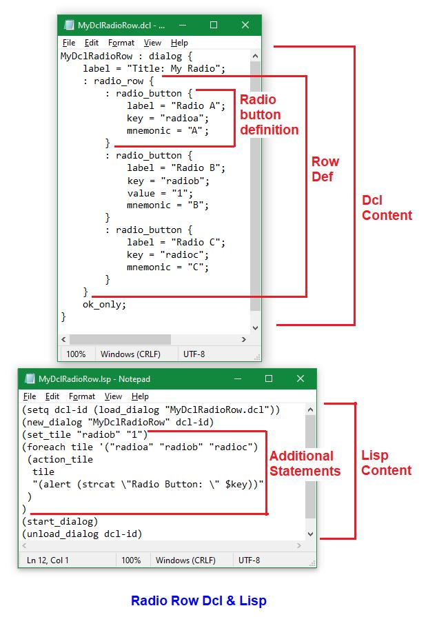
The “Radio” button is the third button type dcl supports. Radio buttons are typically used to present two or more selection options, and they’re required to be placed in a Radio cluster. The cluster can be defined as either a Row or a Column (see Figure 7).
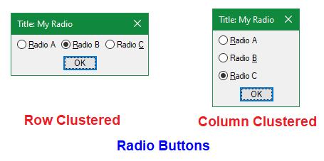
Unlike a Toggle button a Radio button is round “O” in shape. When a Radio button is selected the inner part of the round circular shape is filled in leaving a white outer circle shaped border “O”. In a cluster when a Radio button is selected the previous Radio button is automatically unselected because only a single Radio button can be selected at a time.
Rumor has it that this type of button got its name from those depressible buttons on a traditional
radio. To properly select a radio station when one button is depressed the previously depressed button automatically pops out.
The dcl code needed to generate this type of button for both Row and Column clusters is as follows:
1. Open Windows Notepad application
2. For Row cluster enter the code exactly as shown under Dcl content (see Figure 8)
3. Save the file into folder Documents\Dialog Fun Facts Buttons with the filename: MyDclRadioRow.dcl
4. Open another Notepad session
5. For Column cluster enter the code again this time exactly as shown under Dcl content (see Figure 9)
6. Save the file into folder Documents\Dialog Fun Facts Buttons with the filename: MyDclRadioColumn.dcl
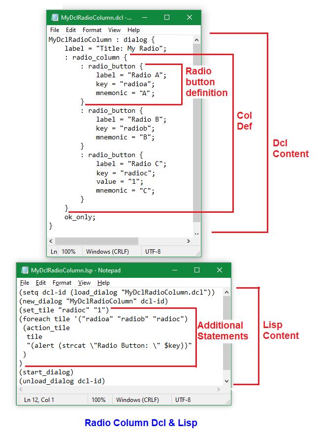
Figure 7
Figure 9
Figure 8
In both of these examples, the Radio button custom dialog boxes’ names are respectively called MyDclRadioRow and MyDclRadioColum (these are case sensitive). The second line is the label or text that is displayed on the dialog box title bar. The next line begins with the cluster type: radio_row or radio_column. This is followed by a group of lines defining each Radio button starting with the call out as: radio_button.
Like the Toggle button the Radio button’s label is optional. Each of the Radio buttons has its own unique key: “radioa”, “radiob” and “radioc” (these are all case sensitive). Again, the key is what the lisp code uses to reference each button.
Like the Toggle button, the value is optional and when set to “1” this means the Radio button is Selected at the time when the dialog box appears on the screen. In the Row cluster example, the Radio B labelled button has this value set while in the Column cluster example, the Radio C labelled button has this value set. Like the Toggle button, the Radio button’s value can also be set in the lisp code. Each Radio button can have its own mnemonic letter defined as the shortcut letter (Alt + letter key combination).
The lisp code needed to load both the Row and Column cluster Radio buttons are as follows:
1. Open Windows Notepad application
2. For Row cluster enter the code exactly as shown under Lisp content (see Figure 8)
3. Save the file into folder Documents\Dialog
Fun Facts Buttons with the filename: MyDclRadioRow.lsp
4. Open another Notepad session
5. For Column cluster enter the code exactly as shown under Lisp content (see Figure 9)
6. Save the file into folder Documents\Dialog
Fun Facts Buttons with the filename: MyDclRadioColumn.lsp
Like both the Push button and the Toggle button dialog boxes, the same lisp functions are used on the Row and Column cluster Radio button dialog boxes to load (load_dialog), show (new_dialog), start (start_dialog) and unload (unload_dialog). The differences in this case are:
1. Dcl filenames:
“MyDclRadioRow.dcl” and “MyDclRadioColumn.dcl”
2. Dialog names:
“MyDclRadioRow” and “MyDclRadioColumn”
Also, similarly there are additional statements in between showing the dialog and starting the dialog box.
First, as I indicated earlier, the value attribute can be set using the set_tile function by referencing the corresponding key attribute:
(set_tile “radiob” “1”) = Radio B labelled button
Selected (set_tile “radioc” “1”) = Radio C labelled button
Selected
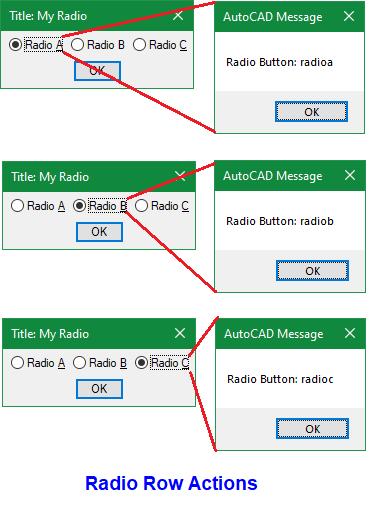
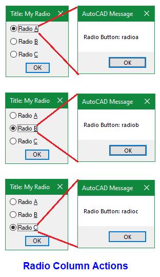
Next, the action_tile function defines what happens when any one of the Radio buttons are selected. In both Radio Row and Radio Column lisp examples a foreach function statement is used to apply the same alert function. But depending
AutoCAD
on which of the three Radio buttons are selected the alert message uses $key to reference the corresponding key attribute (see Figure 10 and 11).
11
Finally, to load and run the dcl and lsp files, type these at the command prompt followed by an Enter ←:
(load “MyDclRadioRow”)
(load “MyDclRadioColumn”)
ANOTHER BRIEF BUTTON BREAK
So far, I’ve mentioned the Windows’ Notepad program as the code editor for both dcl and lsp files. But when code becomes more intense
(requiring lines more than the number of buttons I have on my shirt), this is when I would switch over to Autodesk recommended Visual Studio Code (VS Code). In addition to being able to debug the code directly within AutoCAD I see the following advantages to using VS Code:
1. A single document can be opened for editing and displayed in multiple windows making it possible to edit different sections of the code simultaneously without having to manually jump from one section of the code to another
2. More than one document can be opened for editing at a time so it’s easy to reference, copy and paste code from one document to another
3. Color coding to match open and close brackets and parenthesis makes it easy to visualize the formatting of various function statements
4. With various extensions installed such as the AutoLISP extension as you type out function names, this is either automatically completed for you, or you are presented with a list of similar function names for selection eliminating the need to look them up
5. Online look up of already typed out functions can be done simply with a right mouse click and selecting from the menu Open Online Help
6. See custom functions as fully expanded vs collapsed making it convenient for you to visualize the entire function code vs just the defun statement
7. Line numbers are shown in the left column making it easier to reference the location of the various portions of the generated code
Ok, just hold onto your buttons because there’s still one more button type to discuss and it’s a doozy.
4. THE IMAGE BUTTON
The fourth and final button type that dcl supports is properly named as the “Image” button. Besides being selectable this button type offers the following four graphic display options (see Figure 12):
1. Display a Slide generated by AutoCAD’s Mslide command – file type with extension sld
Figure
2. Display a slide generated by AutoCAD’s Mslide command stored inside an AutoCAD Slide Library file created using AutoCAD’s Slidelib.exe – file type with extension slb
3. Display Vector lines drawn using twodimensional start and end point coordinates –sets of x y coordinates
4. Display a Color filled area using one of the AutoCAD Color Index (ACI) numbers – numbers 1 to 255
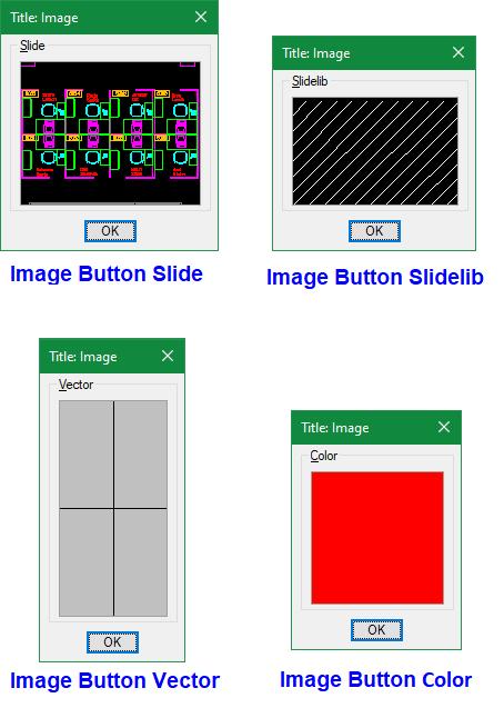
Unfortunately, Image buttons do not support the displaying of raster images (file types with extension such as bmp, jpg, png, tif or wmf).
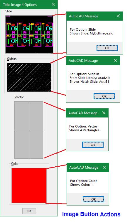
Note: Dcl also supports a tile called image which is similar but different than the dialog definition calls out as: image_button. The main purpose of the Image tile is to display an image using one of the four options mentioned previously. But the Image tile does not support the selection action callback feature which the Image button type does support (see Figure 13).
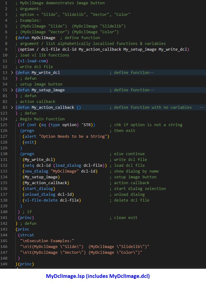
As for the dcl and lsp codes, I’m going to demonstrate how to use a single lisp function MyDclImage.lsp (see Figure 14) to first generate the dcl code on the fly (as discussed also in my original Dialog Fun Fact #3 article) and then continue by handling the displaying of all four Image button options.
As I mentioned earlier, since this code is a lot more intense, I recommend using VS Code to enter the contents of MyDclImage.lsp and save it under folder Documents\Dialog Fun Facts Buttons.
I typically like to include comments at the beginning of the lisp file to provide information as to what the code does, state number of arguments if any and examples on how to implement (lines 1 to 6, see Figure 14). A similar set of examples on
Figure 12
Figure 13
14
implementation is printed to the command line after the successful loading of the file (lines 143 to 149, see Figure 14).
Like the lisp codes for the previous three button types, the Image button code contains similar function statements (lines 132, 133, 136 and 137, see Figure 14).
Figure
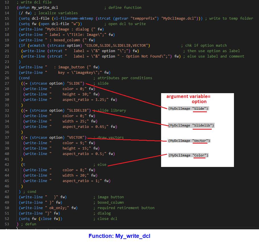
But the first major difference with the Image button code is the added custom My_write_dcl function (line 131, see Figure 14). Instead of loading an already generated dcl file, this function writes the dcl file at the time of the lisp file’s execution (lines 13 to 53, see Figure 15).
In addition to getting around the limitation of dealing with a separate static content dcl file, a major advantage to writing the dcl file on the fly is the ability to generate different dcl file content depending on which option variable is executed:
The My_write_dcl function evaluates the option variable given using the cond function statements and then accordingly writes the corresponding content to the dcl file (see Figure 16).
Figure 15
Slide, Slidelib, Vector and Color (see Figure 15).
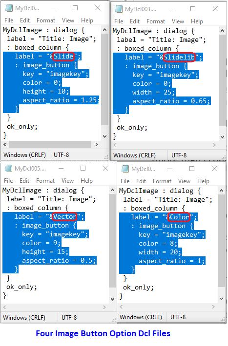
Now, unlike the other three button types the Image button does not support a label attribute. I tend to use either the boxed_row or in this example the boxed_column tile which supports a label attribute as a label for the Image button.
Using the optional Color attribute the Image button can be displayed filled initially with a Color number (1 to 255) or one of the following numbers:
0 or -2 = Current graphic drawing background color
-15 = Current dialog box background color
-16 = Current dialog box foreground color (text)
-18 = Current dialog box line color
The size of the Image button can be defined in the dcl using both the width and height attributes. But I tend to define the size using just one or the other and then use the aspect_ratio attribute to specify
the ratio of an Image button’s width to heightwidth divided by height (see Figure 16).
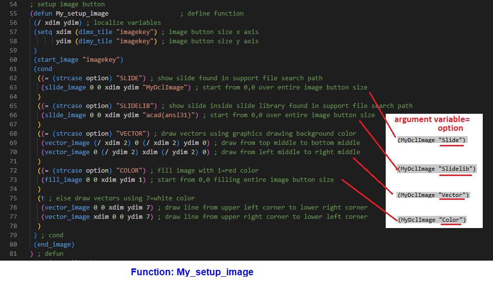
Next, after loading the generated dcl file on the fly and showing it on the screen with the dialog name “MyDclImage” (lines 132 and 133, see Figure 14) the second major difference with the Image button code is the added custom My_setup_image function (line 134, see Figure 14). This function determines what option to display in the Image button (lines 55 to 81, see Figure 17).
Initially, the My_setup_image function retrieves the dimensions (width and height) of the Image button using dimx_tile and dimy_tile functions and saves these to the following variables respectively xdim and ydim (lines 57 to 59, see Figure 17). Next the start_image function is executed to prepare the displaying of one of the four Image options (line 60, see Figure 17). Then like the My_write_dcl function the My_setup_image function evaluates the option variable using the cond function statements to determine which of the following options to execute:
Slide and Slidelib = slide_image function followed by a pair of x and y coordinates (start corner and end corner defining the display area) and ending with either the slide name or the slide library with the slide name enclosed in parenthesis (file type extensions sld and slb are not required)
Vector = vector_image function followed by a pair of x and y coordinates (start point and end point of line drawn) and ending with the color number to display the line (multiple vector_image functions can be executed to draw multiple lines with the designated color)
Color = fill_image function followed by a pair of x and y coordinates (start corner and end corner defining the display area) and ending with the color number to use to fill the tile (supported color numbers are 0, 1 to 255, -2, -15, -16 and -18)
Note for this example:
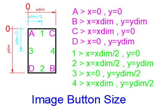
The Slide, Slidelib and Color options all specify a pair of x y coordinates that cover the entire size of the Image button. The first set of x y coordinates begin at 0 0 which is the upper left corner of the Image button tile point (A). The second set of x y coordinates end at xdim ydim which is the lower right corner point (B) defining the entire size of the Image button tile (see Figure 18).
Figure 16
The Vector option, on the other hand, includes twoline drawing statements. The first drawn line starts in the middle of the top of the Image button tile point (1) and ends in the middle of the bottom of the Image button tile point (2). The second drawn line starts in the middle of the left of the Image button tile point (3) and ends in the middle of the right of the Image button tile point (4) (see Figure 18).
For the Slide option to work with this example, you will need to create a slide file called MyDclImage (with file extension sld). First open any drawing file like AutoCAD’s sample drawing file found under:
C:\Program Files\Autodesk\AutoCAD 20##\ Sample\Database Connectivity\Floor Plan Sample.dwg
Note: The ## symbols should be replaced with the AutoCAD version number, i.e.: 24, 25 or 26
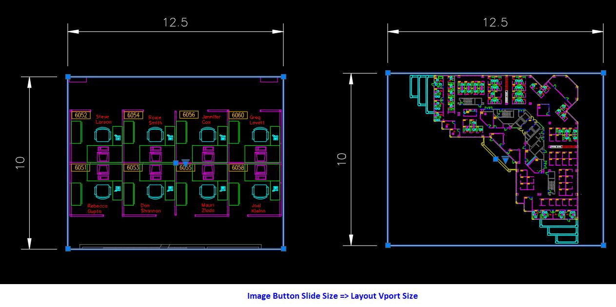
Use the SaveAs command to save this drawing into folder Documents\Dialog Fun Facts Buttons and call it MyDclImage.dwg. To create a slide matching the proportions of the Image button I typically create a Viewport using the Mview command in the Layout tab. Since the dcl for the Slide defines the height as 10 with an aspect ratio of 1.25 (see Figure 16), taking 1.25 divided by 10 would derive the width equal to 12.5 The Viewport is then drawn using 12.5 as the width and 10 as the height. Then click inside Viewport or enter the Mspace command. Next, use the Zoom command to window in to look at just a portion of the floor plan or the entire floor plan sample drawing (see Figure 19).
Finally, enter command Mslide saving the slide under folder Documents\Dialog Fun Facts Buttons with file name MyDclImage.sld
Figure 18
Figure 17
As for the Slidelib option, you do not have to create a slide library file for this to work because the code calls for a slide library file named acad (with extension slb) which comes installed in each version of AutoCAD. The slide name (enclosed in parenthesis) within the slide library is called out as ansi31 which represents one of AutoCAD’s standard hatch patterns. Back in the day when AutoCAD implemented icon menus, slides were used as graphic representations displayed in a dialog box for user selection. So, hatch patterns like ansi31 were saved inside acad.slb and used to display in an icon menu for user selection. Though the Hatch command now automatically generates these hatch pattern images on the ribbon or in a dialog box at time of execution and icon menus are no longer used to display them, the acad.slb file is still included with each AutoCAD installation for backwards compatibility. To see where the acad.slb file is currently stored in your AutoCAD installation at the command prompt type this followed by an Enter ←:
(findfile “acad.slb”)
AutoCAD will then return the location of the acad. slb file.
Finally, the third major difference with the Image button code is the added My_action_callback
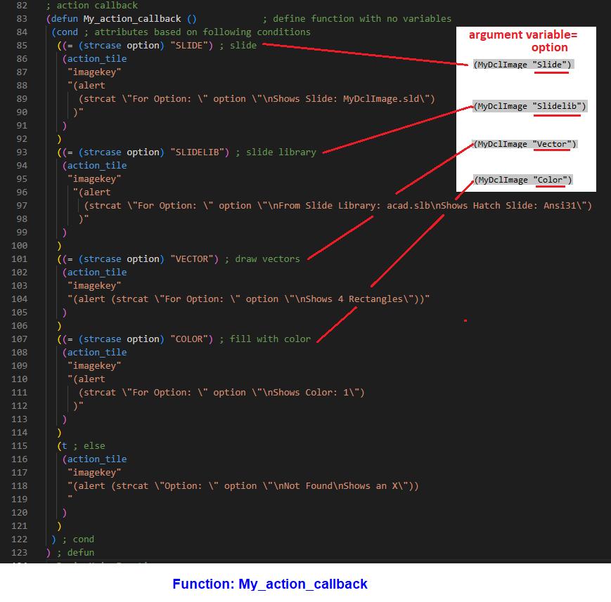
function (line 135, see Figure 14). This custom function determines what action to take when the Image button is selected (lines 83 to 123, see Figure 20).
Just like My_write_dcl and my_setup_image custom functions previously discussed, the My_action_ callback function basically is a giant cond function statement. Depending on which of the following option variable Slide, Slidelib, Vector and Color is implemented and selected then a different alert message is displayed.
Note: There’s an additional function (vl-file-delete) included in MyDclImage.lsp (line 138, see Figure 14). This function deletes the dcl file generated after the dialog box has been dismissed and unloaded.
If you would like to avoid the possibility of typos attempting to enter this huge code manually, you’re welcome to contact me and I’ll gladly email you a digital copy of MyDclImage.lsp.
Finally, to load this lisp file, type this at the command prompt followed by an Enter ←: (load “MyDclImage”)
Then to see the corresponding Image button option displayed type these at the command prompt followed by an Enter ←:
Figure 19
(MyDclImage “Slide”)
(MyDclImage “Slidelib”)
(MyDclImage “Vector”)
(MyDclImage “Color”)
A FINAL BRIEF BUTTON BREAK
For those of you who are interested in viewing slides in, extracting slides from and adding slides to a slide library like acad.slb, download the supported installation file to set up AutoCAD Slide Library Manager (SLM):
1. msi for Windows 64-bit OS
2. exe for Windows 32-bit OS
SLM is an application developed a while ago by Cyrille Fauvel that provides a graphic user interface to manage slide library files. Unfortunately, the setup and installation of this app do not offer the following options:
1. Creating a program group in the Start menu
2. Creating a shortcut to the program on the Desktop
Figure 20
This means you’ll have to figure out where the SLM files are installed.
For Windows 64-bit OS I found them in this location:
C:\Program Files (x86)\Autodesk\Slm
For Windows 32-bit OS I found them in this location:
C:\Program Files\Slide Library Manager
In both cases the app’s execution file is named SLM. exe. To run the app open Windows Explorer to the installed folder location and then double click on SLM.exe.
To create a shortcut of SLM.exe on the Desktop again open Windows Explorer to the installed folder location, select SLM.exe, right mouse clicks and select from the cursor menu: Send to>Desktop (create shortcut)
First, I’ll describe the 64-bit OS version of the app. After launching this version of SLM, the first thing
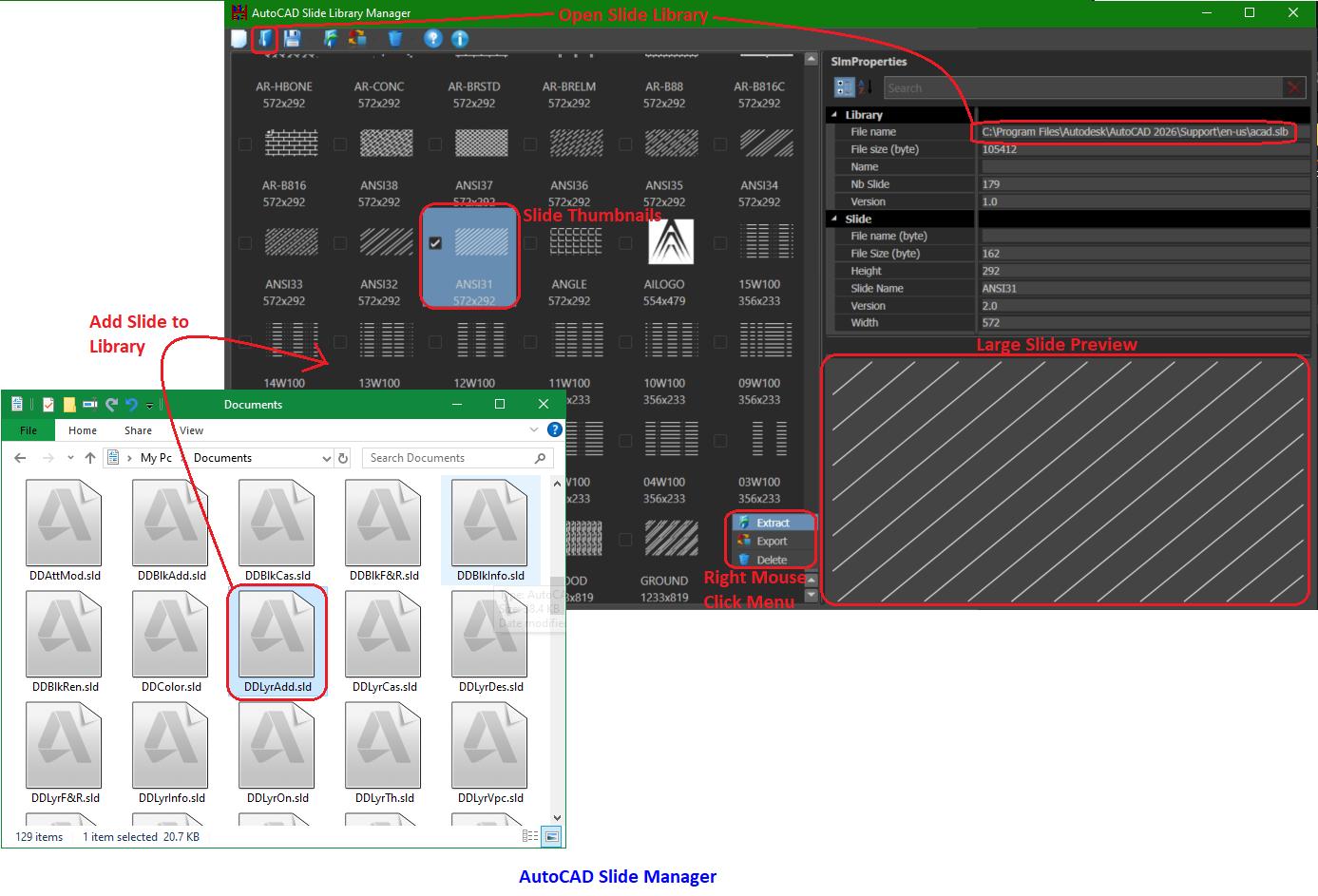
I noticed is that the entire window can be resized to a very small window or expanded to full screen. From the top menu selecting the 2nd icon (blue folder) from the left opens another window to select an existing slide library file such as acad. slb to open. If the loading of this slide library is successful, the large window on the left will display all the slides within this slide library as thumbnails with the name of each slide below. Using the scroll bar on the right side of the large window you can then scroll up and down the thumbnail list. Unfortunately, the thumbnails are only sorted in descending order and there’s no option to choose otherwise. To add slides to the library you can drag and drop existing slides from Windows Explorer onto the large left window. Selecting a slide like ANSI31, an enlarged graphic image of the slide is displayed in a window on the lower right. With a right mouse click you’re offered the option to Extract (as sld), Export (as png) or Delete this slide from the slide library (see Figure 21).
Figure 21
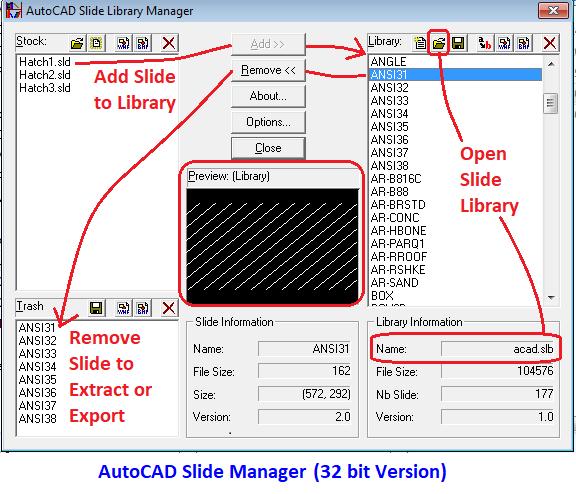
On the other hand, the 32-bit OS version of the SLM app looks very different than the 64-bit OS version. After launching this version of SLM, I noticed that the app window is not stretchable but is fixed in size. There are two list boxes positioned near the top of the dialog box with four Push buttons and a slide Preview window in between. Since this version of the app does not support the feature of dragging and dropping slide files, the top list on the left is designed to open existing slides. Though conversion of slide files to png format is not supported, you can convert selected slides and save them as both bmp and wmf formats. The advantage with a wmf file is that you can use AutoCAD’s built-in WmfIn command to import this file type into any drawing and you’ll be able to work on it as a vector file. You can also add the selected slides from the top list on the left to the top list on the right by clicking on the Add>> button. The list on the right shows slides inside the slide library file which you open by selecting from the top menu the 2nd icon (yellow folder) from the left. After opening the slide library such as acad.slb instead of thumbnail views, only slide names are listed on the top right list box sorted in ascending order with no option to change otherwise. You have the option to select multiple slides from this list and then click on the Remove<< button to place them in the lower left list box where you can select to save them out as sld files or convert and save them out as bmp or wmf files. Selecting a slide from anyone of the three list boxes will show a graphic image of the slide in the Preview window (see Figure 22).
THE BUTTON CONTINUES
Now it’s time to finally button up this article. Just like on physical devices, the button continues to be widely implemented in the digital world’s graphic user interface. AutoCAD dialog boxes are sprinkled with the four button types of the Push button, the Toggle button, the Radio button and the Image button making the selection process not only graphically intuitive but also fun. Hopefully this article has opened many possibilities for you to explore the dialog fun facts encountered when setting up your own buttons in AutoCAD.

Mr. Paul Li graduated in 1988 from the University of Southern California with a Bachelor of Architecture degree. He worked in the Architectural field for small to midsize global firms for over 33 years. Throughout his tenure in Architecture, he has mastered the use and customization of AutoCAD. Using AutoLISP/ Visual Lisp combined with Dialog Control Language (DCL) programming he has developed several Apps that enhance the effectiveness of AutoCAD in his profession. All the Apps actually came out of meeting challenging needs that occurred while he worked in the various offices. He has made all the Apps available for free and can be downloaded from the Autodesk App Store. Though he recently retired from the Architectural profession, Paul continues to write articles depicting his past work experience. Some of these articles can be found in AUGIWorld Magazine where he shares his knowledge learned. Paul can be reached for comments or questions at PaulLi_apa@hotmail.com
BricsCAD® - Building CAD Fluency Through Structured SelfPaced Training
If you are just getting started with BricsCAD® or want to sharpen your CAD skills, Bricsys Learning makes it easy. It’s a self-paced training portal that walks you through the essentials and beyond—no pressure, no fluff. You’ll pick up practical workflows, get comfortable with the tools, and build confidence as you go. Whether you are brand new to CAD, migrating from AutoCAD®, or an existing BricsCAD user who is looking to be more efficient, it’s an excellent way to level up without getting overwhelmed.
While we can’t possibly cover every course (I do recommend taking a look at the other courses available), let’s explore the key sections of the Bricsys Learning site, content structure, step-bystep logic, and how it supports both new users to CAD, BricsCAD users, as well as those users migrating from other CAD software.

WHAT IS BRICSYS LEARNING?
Bricsys Learning is the official online learning center for BricsCAD, offering modular training tracks and self-paced courses designed to teach fundamentals, advanced workflows, and migration methods.
What used to be known as “Bricsys Lessons” is now “Bricsys Learning”, and it is the current destination for fresh BricsCAD and Bricsys® 24/7 training content. The portal is organized into themed learning tracks or videos, and new courses are constantly being added based on demand.
Bricsys’ core mission is straightforward: provide structured, accessible training so that users can adopt BricsCAD confidently, whether they are new to CAD or migrating from AutoCAD®. Let’s see how
these break down within the main functional areas and what each offers.
KEY LEARNING TRACKS AND FOCUS AREAS
1. AutoCAD® to BricsCAD®
This is designed for users already familiar with AutoCAD® who are moving to BricsCAD. Rather than re-teaching CAD basics, it focuses on mapping equivalences, divergences, and mental models. You’ll find videos comparing the user interface (panels, docking, ribbon), (See Fig. 2) navigation and view paradigms (model space, paper space), dialog boxes (print, publish), and how familiar constructs like blocks, styles, and layers carry forward. The different videos explore BricsCAD’s navigation tools (LookFrom), settings and customization dialogs, profile management, and equivalent express tool functions. This section helps reduce friction in the “first days” of using BricsCAD for AutoCAD users.
2. The BricsCAD® Advantage & BricsCAD® Essentials
A hybrid of introductory to intermediate content, split into two sub-streams:
• The BricsCAD® Advantage / Unique Features: It presents the unique toolsets that set BricsCAD apart, such as dynamic 2D UCS, native 3D constraints, adaptive grid snapping, the contextual “Quad” interface, and advanced tools like Blockify, MoveGuided, or CopyGuided. It also delves into systemlevel capabilities like Drawing Explorer and performance settings, helping users see not just how to do things, but why BricsCAD offers a different (and often more fluid) model.

• BricsCAD® Essentials / Core Workflow: Think “Getting Started”. It offers a walkthrough of the interface, settings customization, use of the Quad, how to manage user profiles, how to open and manipulate DWG files, entity snaps/tracking, block insertion and manipulation, core 2D drafting tools, selection modes, and foundational 3D navigation and modeling workflows.
3. Customizing BricsCAD’s User Interface
To maximize efficiency, this section tackles how to tailor BricsCAD’s interface to your personal workflow. Lessons cover customizing workspaces, managing partial CUI files, applying rollover tips, and configuring the Quad for context-aware behavior. (See Fig. 3) Rather than basic UI settings, explore how to sculpt the environment—toolbars, keyboard aliases, menu structure—so that day-to-day productivity rises.
4. Migrating to BricsCAD
This is aimed at users or firms moving legacy AutoCAD® workflows into BricsCAD. Its focus is on the elements that often cause friction during migration: partial customization files (menus, toolbars, aliases), linetypes, hatch patterns, templates and DWT files, plot configurations, tool palettes, custom alias files, shape files, and popular LISP routines or scripts. (See Fig. 4) It helps guide users through a methodical “lift and shift” of CAD standards and automation into the new environment. Download the BricsCAD Migration Guide Here.
5. BricsCAD’s Vertical Essentials
Beyond the focus areas, Bricsys Learning offers modules for specialized workflows:
• BricsCAD Mechanical for 2D Design & Drafting: This is where the platform’s mechanical focus comes alive. Lessons teach how to start from existing design data, add details, and generate complete production documentation. Learners
explore drawing templates, power dimensions, mechanical symbols, and how to output from 3D models with exploded views, parts lists, and bills of materials.
• BricsCAD Mechanical Essentials: A deeper dive into mechanical workflows, covering assembly design, sheet metal modeling, parametric design tools, and production drafting. This module is essential for anyone considering BricsCAD Mechanical as a daily design platform.
• BricsCAD BIM Essentials: is tailored for CAD users ready to transition from traditional 2D drafting to intelligent 3D modeling. Whether you’re an architect, engineer, or CAD technician, the course equips you with the tools to build, enrich, and document BIM models efficiently.
These videos typically show how the core BricsCAD foundations expand into disciplinespecific routines: creating building elements, applying constraints, integrating documentation workflows, and combining modeling and drafting in one DWG environment.
LEARNING EXPERIENCE & MINDFUL DESIGN
Bricsys Lessons are grouped into meaningful videos so learners can see a logical progression without being overwhelmed by a massive catalog. This modular breakdown enables users to pick specific tracks (e.g., “Customizing UI” or “Migrating workflows”) without having to sift through unrelated content.
Self-Paced & Accessible 24/7
Bricsys Learning is entirely self-paced. Users can move at their own speed, revisit videos, and skip ahead if they are already comfortable with parts of the content. The portal encourages exploration without rigid prerequisites.
Fig. 2
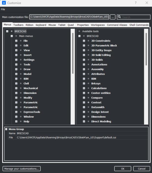
Hands-On Focus, But Not Overwhelming
Rather than presenting only lectures, many videos incorporate demonstrations, walk-throughs, and guided workflows, as well as providing exercise files.
Bridging Theory and Practice
The content is designed to be practically oriented. In the Migration to BricsCAD, you’ll see real-world techniques, moving styles, and aliases. In the BricsCAD Advantage, you’ll see demonstrations of tools like Adaptive Snaps or Blockify solving drafting problems. The approach is not purely textbook but grounded in showing how features apply to real drafting and modeling challenges.
SAMPLE FLOW: A LEARNER’S PATH
Stephanie is a CAD user who is migrating to BricsCAD and wants to maintain productivity while
doing so. She logs into Bricsys Learning and chooses the AutoCAD® to BricsCAD®. She begins by watching side-byside comparisons of the user interface, dialog boxes, and workspace paradigms. She immediately gets a sense of where things are familiar—and where they differ.
From there, she switches to BricsCAD Essentials to build confidence in basic workflows: navigating, drafting, snapping, and using the Quad. Once she’s comfortable, she visits the BricsCAD Advantage to explore the tools that will make her more efficient, discovering tools like the Manipulator and Drawing Health. Finally, she dives into Migrating to BricsCAD, transferring her old drawing templates, custom linetypes, tool palettes, and LISP routines into the new environment. That said, Stephanie may choose to set up her environment first, which is also completely up to her.
Optional vertical videos, for BIM or mechanical workflows, are available once those foundations are built.
At any point, Stephanie can pause, go back, or skip videos—learning at her own pace. If she already knows how to customize user profiles, she can bypass those lessons and move to more advanced customization or migration topics.
Fig. 3
Fig. 4

CERTIFICATE OF COMPLETION
BricsCAD users can now get a Certificate of Completion to show they completed their training and learned something along the way. It’s a simple way to highlight your progress, especially when managers want more than a verbal “I took the course.” This gives them real proof that you’ve put in the time, picked up the skills, and are ready to apply them. Also, what a great way to motivate your colleagues by displaying it or sharing it on social media.
CONCLUSION
The Bricsys Learning portal represents a thoughtful, scalable approach to CAD education, especially for users navigating the transition to BricsCAD. Its modular design helps learners navigate the content without feeling lost, and supports learners at multiple levels: novice, transitioning, and advanced. And let’s not forget the hands-on tutorials in “Get to know BricsCAD” where you can work with sample files and get step-by-step guidance right in the BricsCAD workspace! Users can access these lessons directly in BricsCAD from the Learn panel on the Start Page. (See Fig. 5)
Bricsys is investing not just in delivering a CAD product, but in ensuring its adoption and effective use. Effective utilization of your CAD software is key, and training platforms like Bricsys Learning can make all the difference between software purchase and software mastery.
MORE ABOUT BRICSCAD®
Bricsys® BricsCAD® is the true CAD alternativeoffering a familiar, high-performance 2D and 3D platform that delivers the fastest path from initial design to complete and accurate production deliverables. Built on industry standards with native
.dwg support, BricsCAD ensures full compatibility with existing files and workflows, making switching smooth while reducing costs from day one. With flexible licensing options, powerful automation tools, and significantly lower total cost of ownership, BricsCAD delivers everything you expect from a professional CAD platform.
Download the free, 30-day trial of BricsCAD at Bricsys.com. Would you like free lessons? We have that available with Bricsys Learning Ready to migrate to BricsCAD? Download the Migration Guide. The latest version of BricsCAD improves the tools and features users love, as well as new functionality and UI that supercharge productivity. Around the world, professionals are joining a growing BricsCAD community - backed by a platform that evolves, and a company that puts its users first. Follow us today on LinkedIn and YouTube.

Mr. Craig Swearingen is a Global Implementation Specialist and Consultant at Bricsys. Currently, Craig provides migration and implementation guidance, management strategies, and technical assistance to companies that need a true CAD alternative. Craig spent 19 years in the civil engineering world as a technician, Civil 3D & CAD power user, becoming a support-intensive CAD/IT manager in high-volume production environments. Craig is a longtime AUGI member (2009), a Certified Autodesk® AutoCAD® Professional, and he enjoys networking with other CAD users on social media.
Fig. 5
Bright Ideas for a Bright Future

AUGIWORLD brings you the latest tips & tricks, tutorials, and other technical information to keep you on the leading edge of a bright future.
