ARKORA
Reimagining life along river Brahmaputra
Devashish Mohokar (M. Sc) Rasika Savalekar (M. Sc) Baskar Bharathwaj Subramanian (M. Arch) Nikhil Narendiran (M. Arch)
01 01
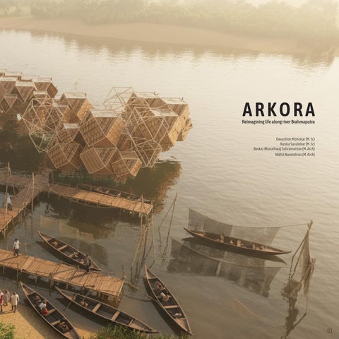
ARKORA
Reimagining life along river Brahmaputra
Devashish Mohokar (M. Sc) Rasika Savalekar (M. Sc) Baskar Bharathwaj Subramanian (M. Arch) Nikhil Narendiran (M. Arch)
01 01