Study a bachelor's degree in architecture at NUS's College of Design and Engineering. GPA:4.1
HIGH SCH / ISA WENHUA IB Program
Guangzhou Foreign Language School
SEPTEMBER 2020 – JULY 2023
IB education has equipped me with interdisciplinary literacy, fostering critical thinking and collaborative skills through indepth research. Won scholarship for three consecutive years.
YEAR 3 SEM 1
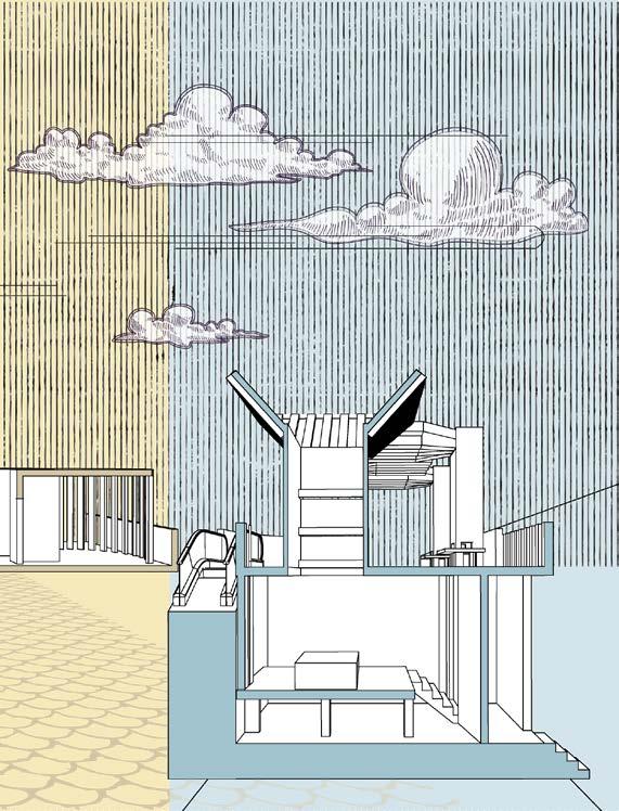
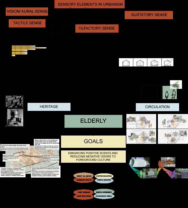
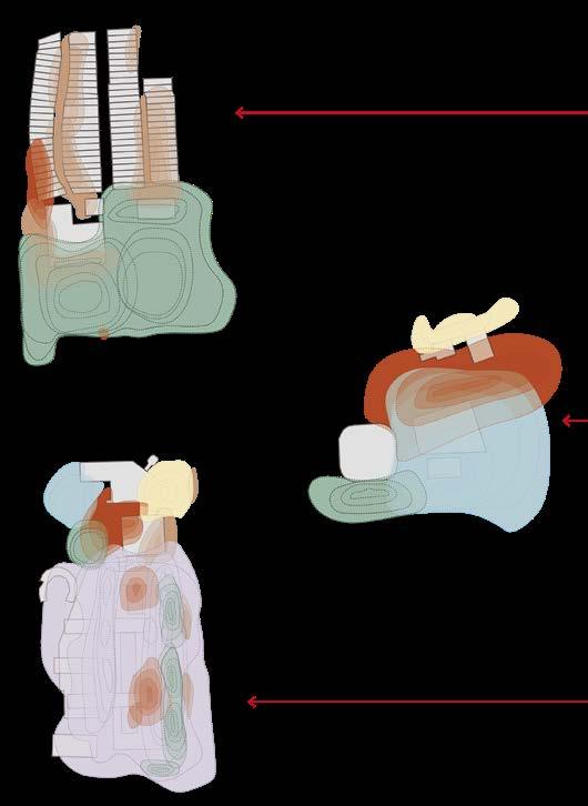
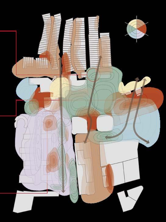
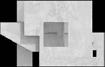
AR3101 OLFACTORY MEMORIES: LINKING HERITAGE AND COMMERCE THROUGH SCENT
YEAR 2 SEM 2
AR2102 HYPENFILANIENT
AR2328 STRUCTURE EXERCISE
YEAR 1 SEM 2
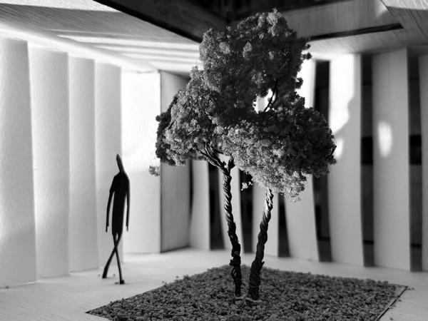
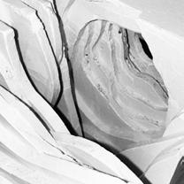
AR1102 SENSORY JOURNEY IN SHODAN HOUSE
AR3101
OLFACTORY MEMORIES: LINKING HERITAGE AND COMMERCE THROUGH SCENT
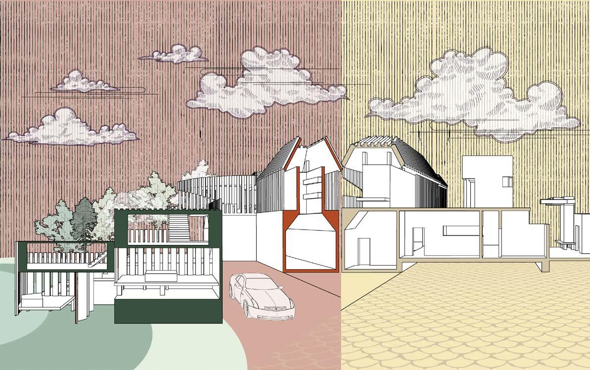
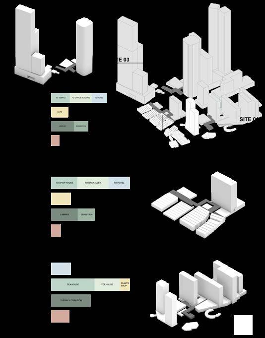
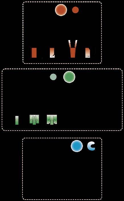
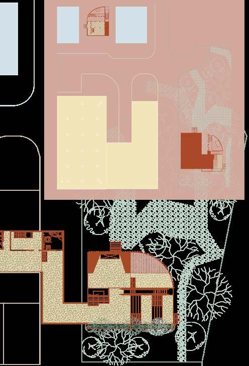
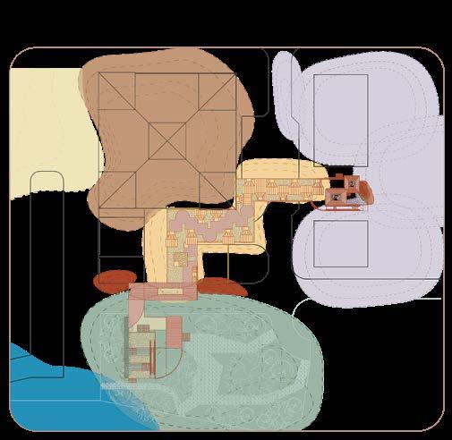
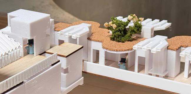
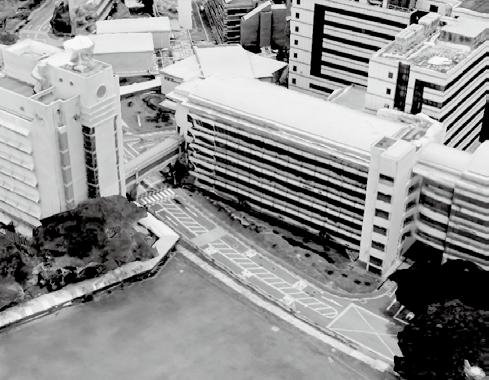
This project investigates the smellscape of Tanjong Pagar and how everyday scents shape memory and spatial experience. It identifies two contrasting groups: unpleasant odors such as smoke and damp air, and positive aromas including coffee, tea, herbs, and greenery. These scents carry collective memories embedded in temples, herbal halls, tea houses, and shophouse kitchens.
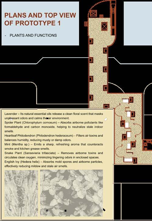
Focusing on elderly residents as living carriers of heritage, the project sees scent as a bridge between past and present. Through small architectural interventions in back alleys, aromatic plants and traditional practices help purify the air while amplifying heritage-related scents, preserving both spatial form and invisible cultural memory.
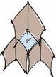
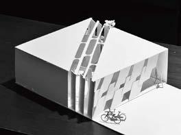
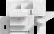
HYPENFILANIENT YEAR2 SEM 2
SCALE/PRECEDENT/CONTEXT
"HYPENFILANIENT" IS A COMBINATION OF "HYPERBOLA", "ENFILADE", AND "DISORIENTATE"
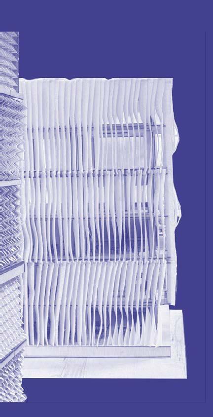
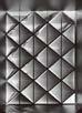
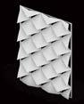
FACADE EXPLORATION
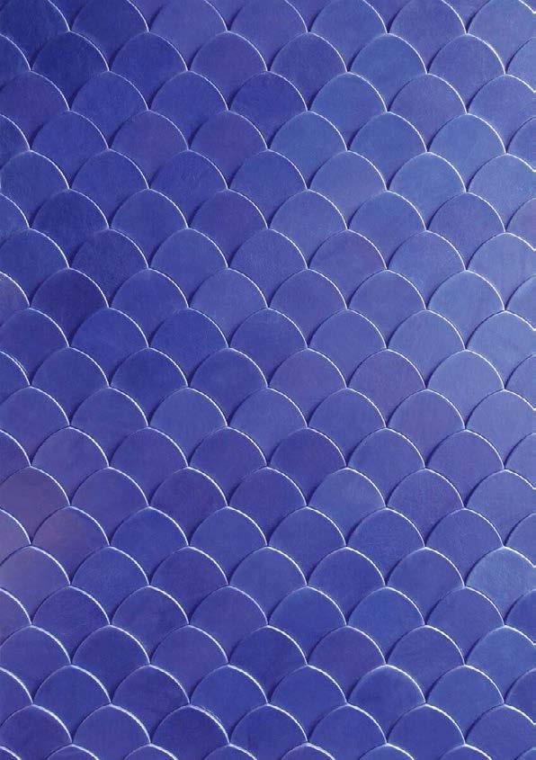
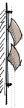
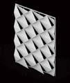
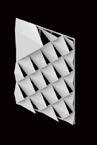
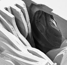
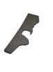
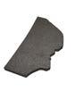
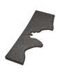
CONCEPT FISH SCALE
DESIGN INTENTION
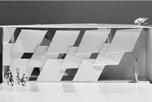
A FISH SCALE-INSPIRED FACADE ENHANCES
CLIMATE ADAPTABILITY BY REGULATING SUNLIGHT, VENTILATION, AND HEAT TRANSFER. ITS LAYERED STRUCTURE ADJUSTS SOLAR EXPOSURE, REDUCES HEAT GAIN IN HOT CLIMATES, AND MINIMIZES HEAT LOSS IN COLD ONES. IT ALSO IMPROVES RAINWATER DRAINAGE AND WIND RESISTANCE, COMBINING BIOMIMETIC AESTHETICS WITH ENERGY EFFICIENCY.
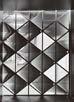
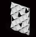
THE MATERIAL AND SPECIAL ARRANGEMENT OF FISH SCALES CAN EFFECTIVELY PROTECT AND ISOLATE THEM FROM RAIN AND SUNLIGHT.
THROUGH THE REFRACTION OF FISH SCALES, STRONG DIRECT LIGHT CAN BE AVOIDED AND SOFT REFRACTED LIGHT CAN BE PRODUCED.RAINWATER CAN BE DRAINED ALONG THE CURVATURE OF THE FISH SCALES.
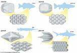
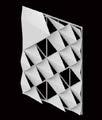
DOUBLE FACADE FISH SCALE
7
CURVED
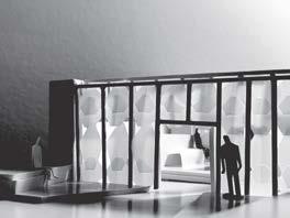
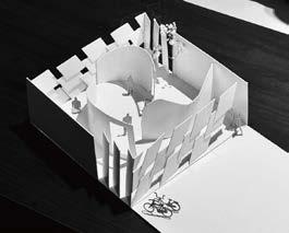
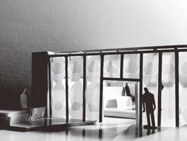
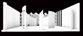
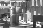
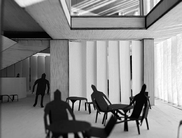
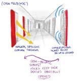
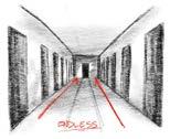
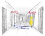
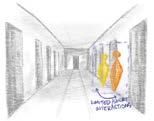
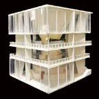
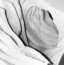
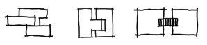
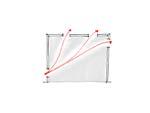
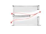
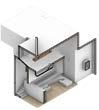
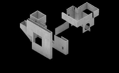
THE LEFT SPACE EMPHASIZES “EXPERIENCE AND DYNAMICS” AND MAY BE AN EXHIBITION SPACE, EXPERIMENTAL SPACE OR A SHARED PLACE FOR THE PUBLIC. THROUGH TRANSLUCENT COMPONENTS AND FLEXIBLE LAYOUT, IT GUIDES USERS TO ACTIVELY EXPLORE THE SPACE AND FOCUSES ON THE INTERACTION BETWEEN PEOPLE AND SPACE.
THE RIGHT SPACE TENDS TO BE “FUNCTIONAL AND DAILY”, SUITABLE FOR ACTIVITIES SUCH AS OFFICE AND LIVING THAT REQUIRE PRIVACY AND STABILITY. THE SPACE ORGANIZATION IS CLEAR, THE USER BEHAVIOR PATH IS CLEAR, AND THE EFFICIENCY AND COMFORT OF SPACE USE ARE EMPHASIZED.
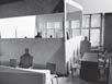
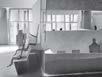
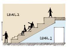
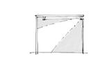
THE LECTURE ROOM IS A DOUBLE-VOLUME SPACE. THE LOWER PART OF THE LECTURE HALL IS A CORRIDOR OF THE FIRST LEVEL, WHICH PROVIDE AN ALTERNATIVE PATH FOR STUDENT TO REACH THE FREE SPACE.
SITE - SPATIAL RATIO (INTERIOR SPACES)
SITE - SPATIAL RATIO (INTERIOR SPACES)
BASIC ROOM UNITS
CLASSROOM
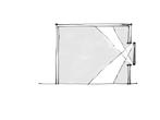
CONSIDERING THE FACADE OUTSIDE THE SPACE IS THE CURVED PART IN THE EXTERIOR FACADE, INTERIOR PARTITION FOLLOW THE SAME LANGUAGE OF EXTERIOR FACADE.
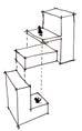
BOX-IN-BOX SPACE
BASED ON CASE A AND THE INVESTIGATION OF THE CORRIDOR IN ROOM THAT CAN ACCOMMODATE 4 PEOPLE.
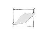
FREE SPACE BY CONTAINING THE DESIGN LANGUAGE FOR FISH CURVE, WE MAKE THE FREE SPACE TWO CURVED PARTITION WHICH CAN LARGELY BOOST THE CIRCULATION.
LECTURE HALL
DOUBLE VOLUME OF THE LECTURE HALL ALLOWS ENOUGH SUNLIGHT TO PROVIDE EFFICIENT LIGHT RESOURCE.
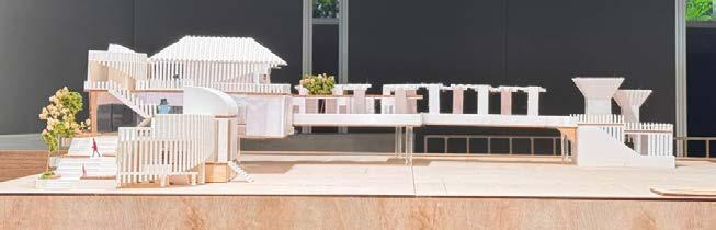
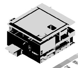
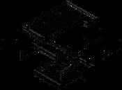
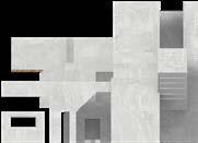
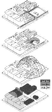
EXPLODED VIEW WITH 3 FACADE
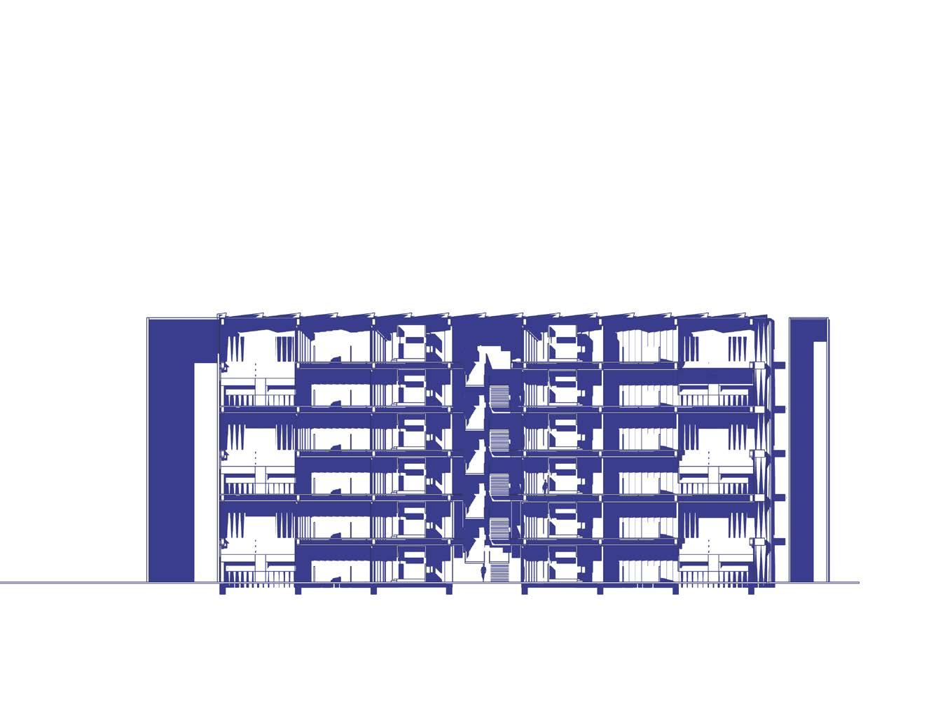
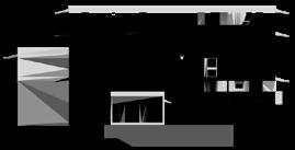
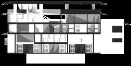
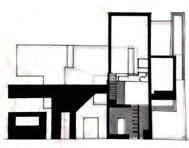
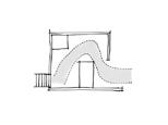
ELEVATIONS
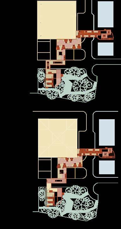
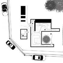
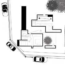
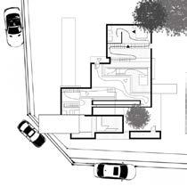
PLAN LEVEL 02 & 03 FUNCTIONS
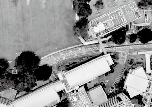
LOWER KENT RIDGE RD PLAN LEVEL 01
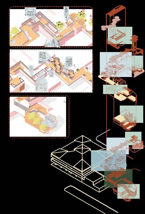
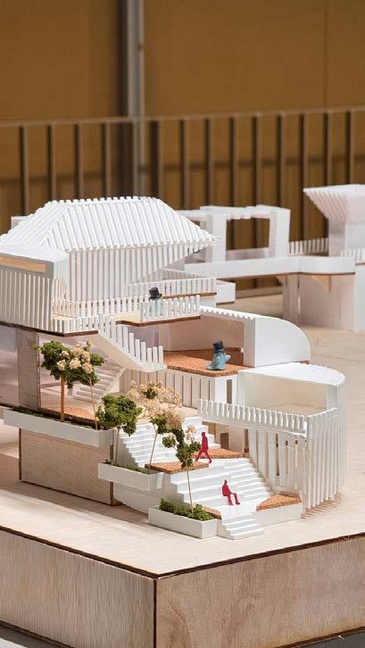
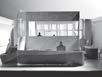
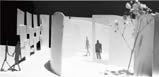
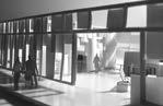
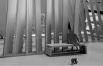
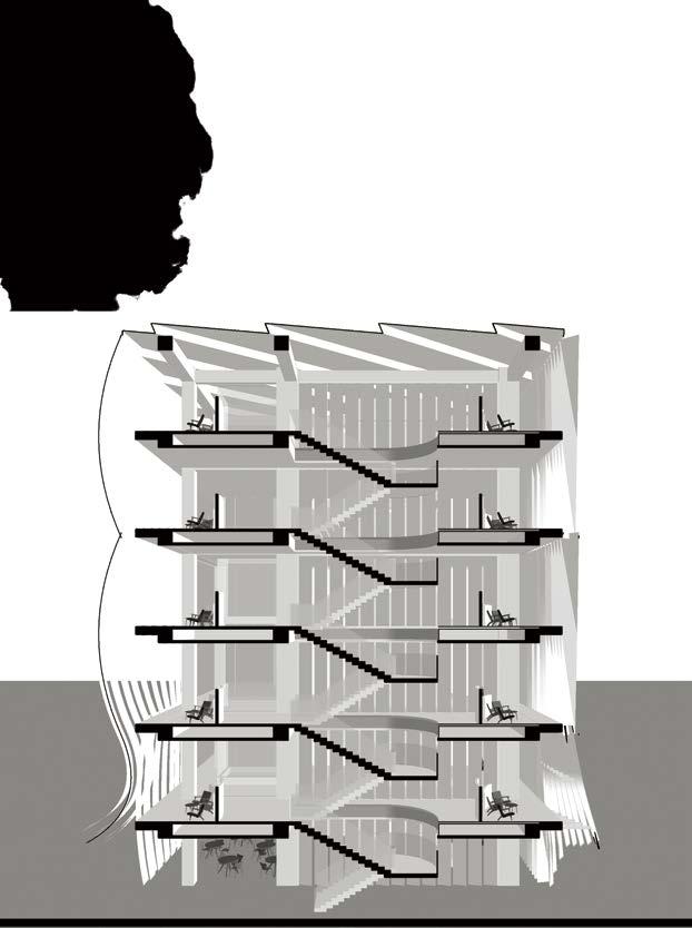
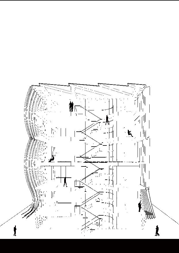
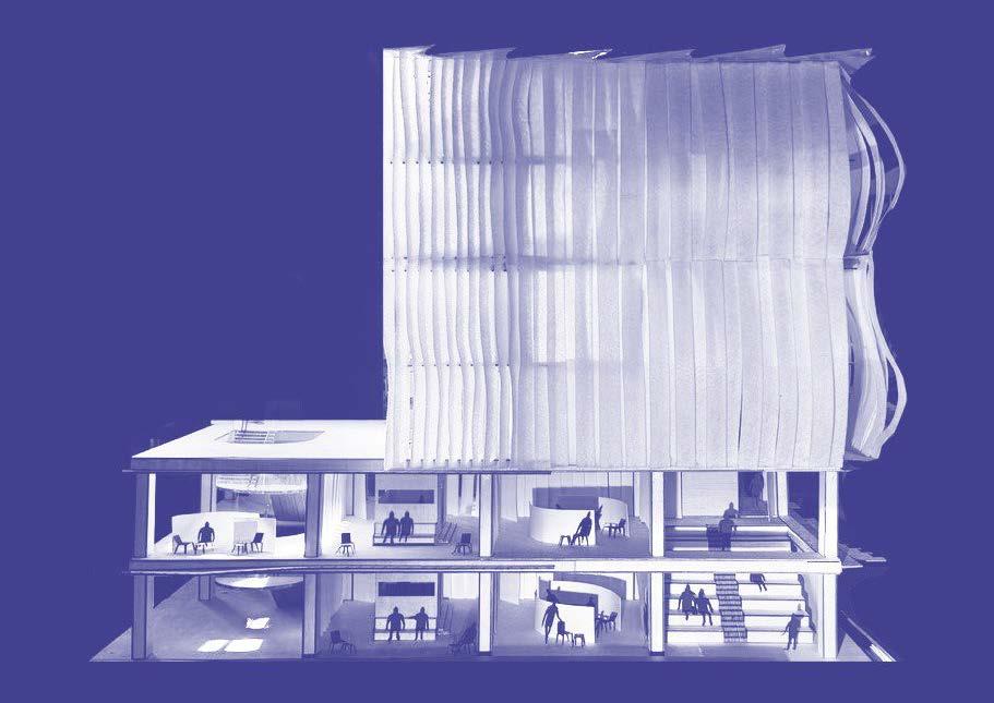
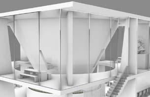
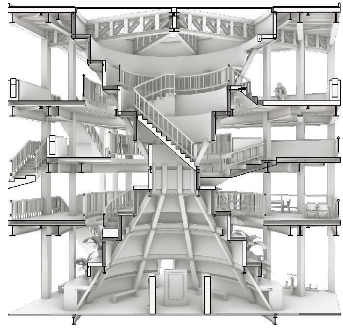
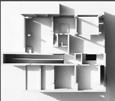
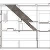
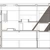
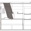
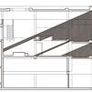
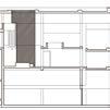
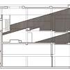
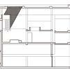
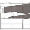
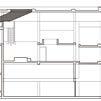
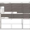
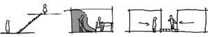
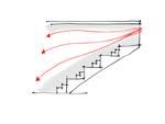
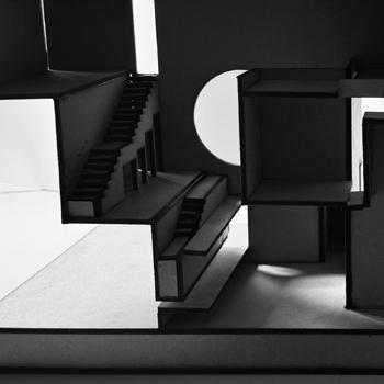
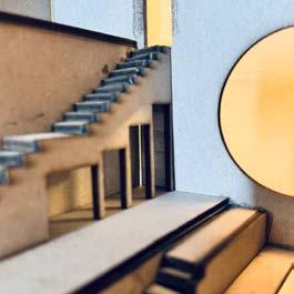
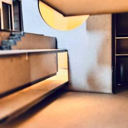
SECTIONAL PERSPECTIVE VIEW
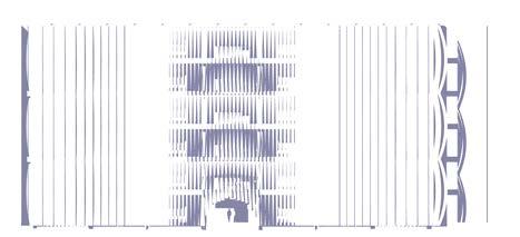
THIS PERSPECTIVE WAS CAPTURED AT THE MAIN STAIRCASE, SHOWING THE THREE FACADES IN THE INTERIOR. IT ALSO REFLECTS THE USER'S MOVEMENT AND SPATIAL FUNCTION.
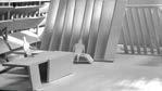
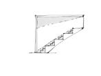
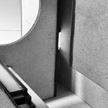
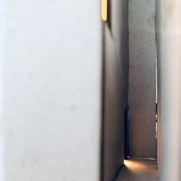
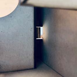
DETAILS IN STRUCTURE
SHOWING THE DETAILS IN THE STRUCTURE OF THE FACADE
PROPOSED A PRACTICAL VIEW FOR FACADE IN REAL LIFE.
EXERCISE YEAR2 SEM 1
STRUCTURAL STUDY
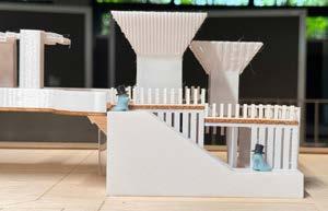
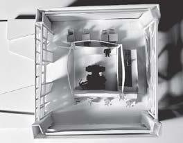
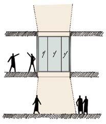
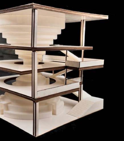
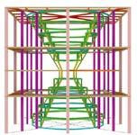
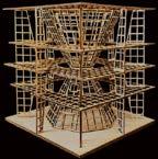
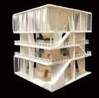
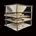
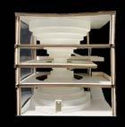
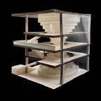
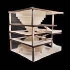
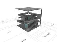
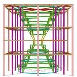
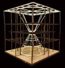
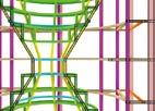
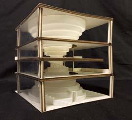
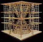
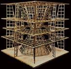
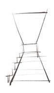
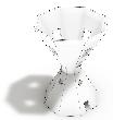
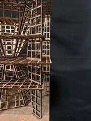
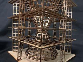
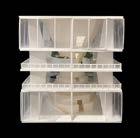
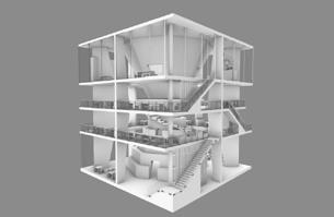
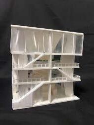
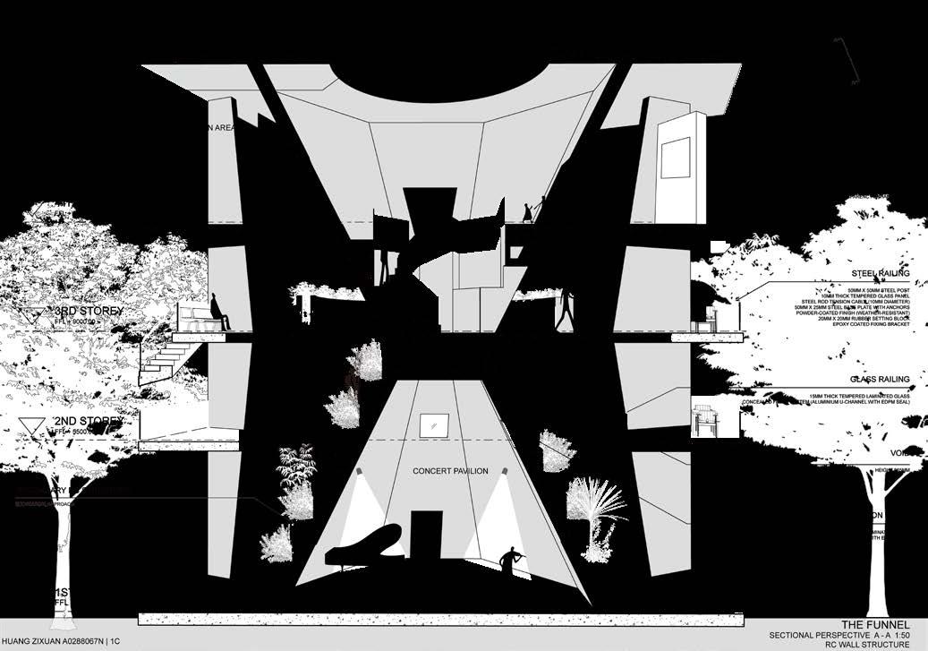
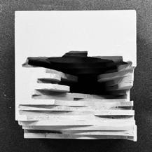
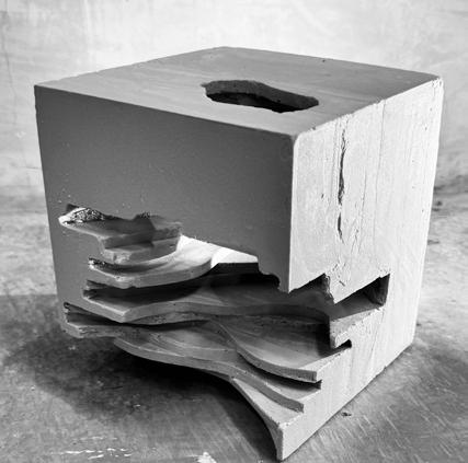
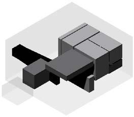
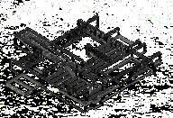
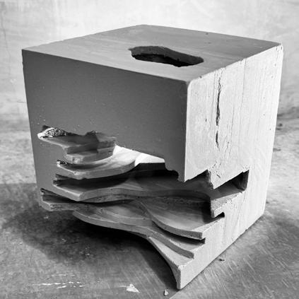
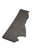
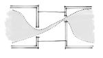
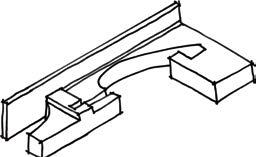
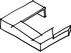
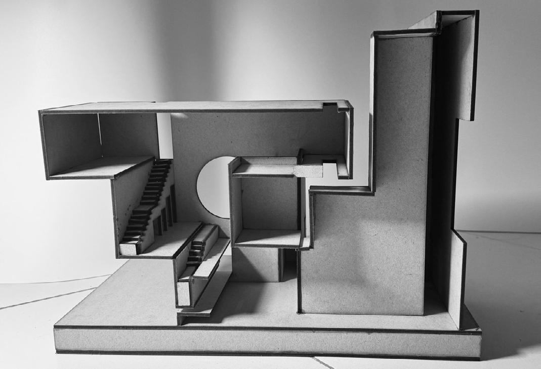
The Funnel was designed with the intention to create a seamless contrast between the funnel and the regular square slabs to emphasis the funnel structure. This serves as the division of space within the structure. Vertical circulation around the funnel serves as a radial view exploitation of the design and a sense of journey while exploring the galleries.
THE FUNNEL
The Funnel was designed with the intention to create a seamless contrast between the funnel and the regular sqaure slabs to emphasis the funnel structure. This serves as the division of space within the structure. Vertical circulation around the funnel serves as a radial view exploitation of the design and a sense of journey while exploring the galleries.
RC WALL STRUCTURE FRAME
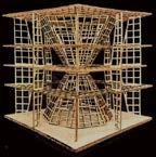
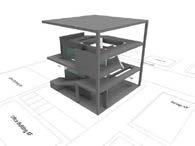
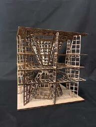
RC Wall structure concept was similarly seperated into two different independent structural system which are the funnel and the outer slabs. Both structure are grounded whith the slab structural system following a radial arrangement. The RC Wall are extruded towards the funnel at the 2nd and 3rd Storey to adjust for the cantilever span due to the shrinking atrium surronding the funnel. The structural arrangement is optimised to allow more porosity towards the funnel from the outside so as to emphasis the core element in the design which is the funnel.
DIMENSIONS OF STRUCTURAL COMPONENTS (PRIMARY)
COMPONENTS (SECONDARY)
Kieron Le Ka Tay Wudi
Huang Zixuan
Yuhui Yu
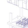
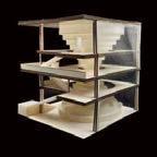
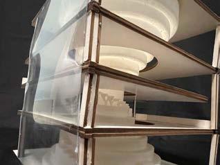
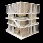
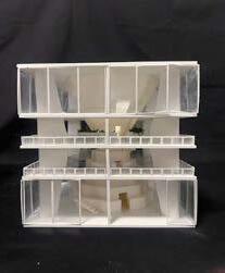
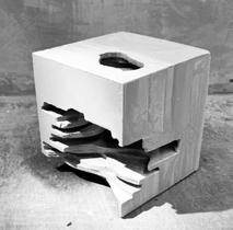
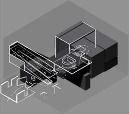
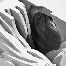
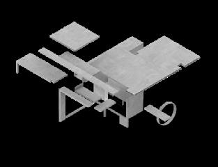
The main concept of this design is the funnel shaped atrium, which is used to seperate the middle private areas and the top and ground more public areas. The funnel serves as a secondary vertical circulation to connect the gallery floors. The cireular funnel would act as a constrast to the square framed structure which highlights the different form and spatial experiences between both. The funnel can be seen as a structural enginner marvel which the entire emphasis of this design proposal would solely focus on the funnel. A skylight connects at the top of the funnel for lighting within the funnel atrium. Our intended proposal follows a design philosophy in which the structure leads to the architectural form. The idea of the middle atrium was formalized and made tangible through the funnel structure in the middle, which serves as the hierarchy in this initial space model. The glass and open facades are used to show clarity of the funnel from the outside and context buildings. THE FUNNEL
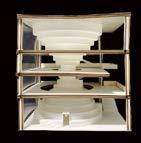
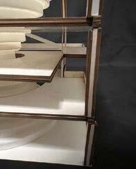
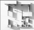
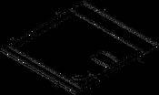
INITIAL SPACE MODEL FLOOR SLAB OUT
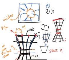
PROCESS SKETCHES INITIAL LAYOUT
GROUP 1C MEMBERS
A0271618B
A0282761Y
Huang Zixuan
Yuhu Yu
A0288067N
A0222942J
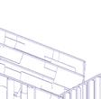
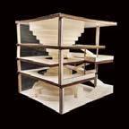
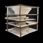
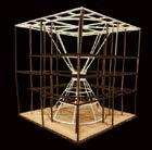
FIRST SPACE MODEL
CONDITIONS AND CRITERIA
1. Site Boundary : 18m x 18m x 18m
2. Atrium connecting all floors
3. 2 Circulations
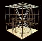
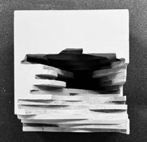
SECOND SPACE MODEL - HYPERBOLA SHAPED ATRIUM
SQUARE VERSION
Kieron Le Kai Tay
Wudi
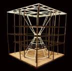
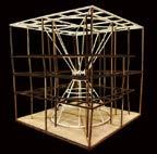
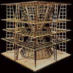
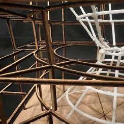
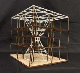
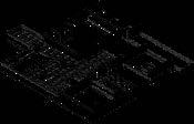
STEEL RIGID FRAME STRUCTURE
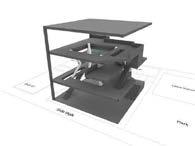
The structural concept initially for our space model proposal was to have one whole structural entity with the funnel structure connected to the roof and transfer the load downwards through outside columns. Our initial space model had our funnel off center, which made it difficult for the funnel structure to be in equilibrium. We decided that centralising the funnel made it more structurally stable as all lateral forces are equal. Circulation within the funnel would now cut through the gaps between the funnel columns. The structure of the funnel and the floor plates of the rest of the building are independent of each other with the inner columns of the floor plates surronding the funnel with the same orientation, indicating the funnel serving as an atrium as well. Another reason for the independent structures is due to having gaps between the floor plates and the funnel so as to provide unobstructed views between floors. Exposed beams connecting the floor plates and the funnel structure would obstruct these views and hinder circulation around the funnel as well. The steel rigid structure proposal takes into account primary steel structure and secondary steel structure as well.
DIMENSIONS OF STRUCTURAL COMPONENTS (PRIMARY)
SLAB STRUCTURE
Girder 1 - 600mm x 300mm x16mm
Beam 1 - 160mm x 80mm x 16mm
Column 1 - 450mm x 450mm
Column 2 - 340mm x 340mm
FUNNEL SECTION
FUNNEL STRUCTURE
Girder 2 - 400mm x 200mm x 16mm
Column 3 - 280mm x 280mm
Truss - Height:900mm
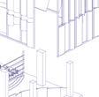
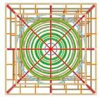
FLOOR PLAN (SLABS)
STRUCTURE FLOOR PLAN
PROCESS SKETCHES
GROUP 1C MEMBERS
Kieron Le Ka Tay
Wudi
Huang Zixuan
Yuhui Yu A0271618B
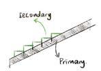
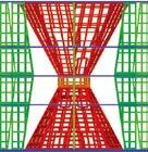
STRUCTURAL HIERARCHY
Our structure has clear definition of primary structure and secondary structure. Particularly in our funnel structure the Beam 2 is the secondary structure which rests on top of the primary structure Girder 2 and Column 3.
CONCEPT
SECONDARY STRUCTURE(PROPOSED)
Beam - 100mm x 50mm x 6mm
Column - 150mm x 150mm x 6mm
STRUCTURAL CALCULATION
Girder 1 - 9000mm/15 = 600mm (Longest standard span) 600m x 300mm (Proposed)
Girder 2 - (13800mm x 3.14)/8 = 5500mm 5500mm/15= 366.67mm (Longest standard span) 400mm x 200mm (Proposed)
Beam 1 - 2300mm/15 = 153.33mm (Shortest standard span) 160mm x 80mm (Proposed)
Column 1 9000mm/20 = 450mm 450mm x 450mm Proposed)
Column 2 6800mm/20 = 340mm 340mm x 340mm Proposed)
Column 3 5500mm/20 = 275mm 280mm x 280mm Proposed)
The Funnel was designed with the intention to create a seamless contrast between the funnel and the regular sqaure slabs to emphasis the funnel structure. This serves as the division of space within the structure. Vertical circulation around the funnel serves as a radial view exploitation of the design and a sense of journey while exploring the galleries.
STEEL RIGID FRAME STRUCTURE
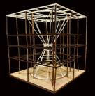
Steel Rigid structure concept was seperated into two independent structural system which are the funnel and outer slabs. The overall arrangement of the columns and beams are radial to the center of the funnel. The funnel has a primary structure and a secondary structure system with the primary steel structure forming the overall shape of the funnel while the secondary steel structure forms the step terraces that envelops the funnel. Both structural system are joint at the roof trusses and girders which are grounded from the outer main columns.
The first space model has hanging spaces that could be used as terraces in the design. This is to create a sort of irregularity with the outer floor slabs.
INTERRELATION
DIMENSIONS OF STRUCTURAL COMPONENTS (PRIMARY)
SLAB STRUCTURE
Girder 1 - 600mm x 300mm x16mm
Beam 1 - 160mm x 80mm x 16mm
Column 1 - 450mm x 450mm
Column 2 - 340mm x 340mm
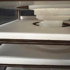
The first space model had cantilevers and a circular atrium which surronds the funnel structure. This is used to connect the the circulation between the funnel as well as the outer floor plates.
GROUP 1C MEMBERS
Kieron Le Ka Tay
Wudi
Huang Zixuan
Yuhui Yu
A0271618B
A0282761Y
A0288067N
A0222942J
The initial hanging floor slab is supported now with a column and supported with a cantilever beam which allows a 3m extension of the floor slab from the inner column. The new space is now indicated with a column due to structural reasons.
The main girders are circular which creates the radial structural system with beams and girders connecting outer ring girders with the inner ring girders to allow a 3m cantilever span, which made the final atrium hole bigger than the first space model.
FUNNEL STRUCTURE
Girder 2 - 400mm x 200mm x 16mm
Column 3 - 280mm x 280mm
Truss - Height:900mm
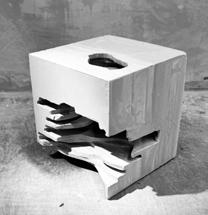
From the first space model, our obvious intention was to create a physical funnel atrium. Our funnel in the first space proposal is circular in shape as a contrast to the regular floor plates.
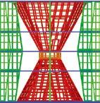
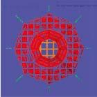
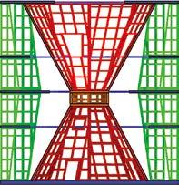
The difference in colour of the structure shows the different independent structural system which are the funnel and the outer plates. The funnel was centralised so as to allow a more structural rigid steel structure as the off-center funnel created an irregular grid which would not structurally work. The funnel structure is grounded through the outer main columns which connects the floor slabs as well.
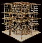
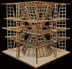
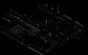
RC WALL STRUCTURE FRAME
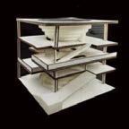
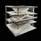
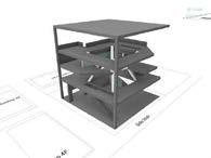
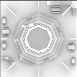
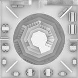
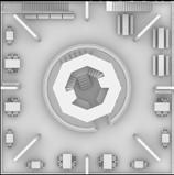
The RC Wall structural concept for our space model is similar to the process for our steel rigid frame structure which there are 2 independent structure system (Funnel and Slab). We proceed with the RC Wall structure rather than the RC rigid strcuture as it would have been similar to our steel proposal. With RC Wall structure, we approached the funnel geometry with a regular octagonal shape for an ideal well balanced arrangement. The angle of tilt of the funnel RC Wall is identified to be ideally above 60 degrees from the ground for the lower half and likewise for the upper half angle from the roof. The arrangement of the RC wall for the slab structure follows a radial arrangement as it provided with the most space on each floor slab to leverage on while providing the neccessary structure. The arrangement spatially provides the least amount of solidity to the overall form of the structure as compared to our previous iterations, allowing for more flexibility n our design. Opening of the roof is a skylight with a 3m cantilever of the roof slab from the walls of the funnel.
PLAN (SLABS)
STRUCTURE
SLAB WALLS (DIMENSIONS)
STRUCTURAL CONSIDERATIONS
1C
DIMENSIONS OF STRUCTURAL COMPONENTS (PRIMARY)
STRUCTURAL CONSIDERATIONS (SECONDARY STRUCTURE)
It was after calculation that the structural joint should be 4m long in a regular octagon shape.
If <4m, space in the base of the upper funnel will be constrained to perform any circulation activities.
Likewise the angle of tilt will be below 60 degrees which was deemed not structurally sound.
If >4m, the width of the step terraces is too small to support any objects.
STRUCTURAL CONSIDERATIONS (OPENINGS)
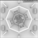
The openings in the wall are porportionally small to it’s overall wall to maintain the rigidity of the wall. The openings occur every other side for a well balanced arrangement while maintaining the solidity of the wall. Openings at the top of each halves is to also lower the center of gravity of each wall to make the overall structural configuration more stable.
STRUCTURAL CALCULATION
Thick
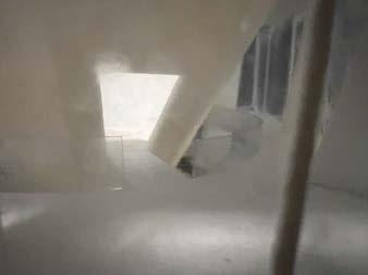
Skylight
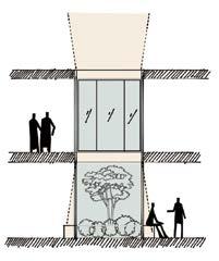
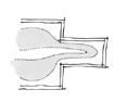
THE FUNNEL
The Funnel was designed with the intention to create a seamless contrast between the funnel and the regular sqaure slabs to emphasis the funnel structure. This serves as the division of space within the structure. Vertical circulation around the funnel serves as a radial view exploitation of the design and a sense of journey while exploring the galleries.
RC WALL STRUCTURE FRAME
RC Wall structure concept was similarly seperated into two different independent structural system which are the funnel and the outer slabs. Both structure are grounded whith the slab structural system following a radial arrangement. The RC Wall are extruded towards the funnel at the 2nd and 3rd Storey to adjust for the cantilever span due to the shrinking atrium surronding the funnel. The structural arrangement is optimised to allow more porosity towards the funnel from the outside so as to emphasis the core element in the design which is the funnel.
Exploiting the boundaries offset gaps of the floor slabs from the structural components to provide the sufficient space for the secondary circulation in the proposal.
INTERRELATION
However, the RC Wall span takes up a larger space than the initial offset from the first space model so the width of the stairs is narrowed down to 1000mm from the initial 1500mm
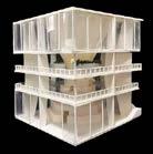
From the first space model, the proposal was being held by thse 4 columns at the corners of the slabs, proposing a very long span column. This was to allow a more porous facade for the proposal as to emphasize the funnel structure. The facade was initially planned to be a glass wall system.
From the structural study of the requirements of the RC Wall structure frame, we decided to leverage on a well-balanced arrangement of the wall to frame our funnel structure. This can be seen as the outer structural system as a secondary structure system to the main funnel structure which emphasizes the structural hierarchy in the design proposal.
DIMENSIONS OF STRUCTURAL COMPONENTS (PRIMARY) COMPONENTS (SECONDARY)
SLAB STRUCTURE FUNNEL STRUCTURE
RC Floor Slab -300mm
RC Terrace Slab -150mm RC Wall -300mm
GROUP 1C MEMBERS
Wall - 475mm
Floor Slab - 1500mm (Solid)
From the first space model, our obvious intention was to create a physical funnel atrium. Our funnel in the first space proposal is circular in shape as a contrast to the regular floor plates.
We decided to go forward with an octagonal shape funnel which stills follows the well-balanced arrangement.The top half of the funnel is connected to the bottom half which is grounded via a thick RC slab at the center as a structural support. The tilt angle is kept at a safe angle of 62 degrees from the ground as to have a wide enough terrace and structural stability. The funnel was made centralised to prevent a complex structural system.
THE FUNNEL
The Funnel was designed with the intention to create a seamless contrast between the funnel and the regular sqaure slabs to emphasis the funnel structure. This serves as the division of space within the structure. Vertical circulation around the funnel serves as a radial view exploitation of the design and a sense of journey while exploring the galleries.
RC WALL STRUCTURE FRAME
RC Wall structure concept was similarly seperated into two different independent structural system which are the funnel and the outer slabs. Both structure are grounded whith the slab structural system following a radial arrangement. The RC Wall are extruded towards the funnel at the 2nd and 3rd Storey to adjust for the cantilever span due to the shrinking atrium surronding the funnel. The structural arrangement is optimised to allow more porosity towards the funnel from the outside so as to emphasis the core element in the design which is the funnel.
RC Funnel Wall - 200/4500 x 8500(Highest Ceiling Span) x 1.2 (angle threshold) = 453mm ~ 475mm (Proposed)
RC Core Floor Slab - 1500mm (Solid)
Thick Slab to serve as a structural joint for both halves of the funnel to balance out the lateral forces and moments hence needing a thick structural component to support both halves of the funnel
SECONDARY STRUCTURE
RC Terrace Floor Slab = 150mm
eron K Le Kai Tay
Wudi
Huang Zixuan
Yuhui Yu
A0271618B
A0282761Y
A0288067N
A0222942J
DIMENSIONS OF STRUCTURAL COMPONENTS (PRIMARY)
COMPONENTS (SECONDARY)
THE FUNNEL
The Funnel was designed with the intention to create a seamless contrast between the funnel and the regular sqaure slabs to emphasis the funnel structure. This serves as the division of space within the structure. Vertical circulation around the funnel serves as a radial view exploitation of the design and a sense of journey while exploring the galleries.
RC WALL STRUCTURE FRAME
RC Wall structure concept was similarly seperated into two different independent structural system which are the funnel and the outer slabs. Both structure are grounded whith the slab structural system following a radial arrangement. The RC Wall are extruded towards the funnel at the 2nd and 3rd Storey to adjust for the cantilever span due to the shrinking atrium surronding the funnel. The structural arrangement is optimised to allow more porosity towards the funnel from the outside so as to emphasis the core element in the design which is the funnel.
INTERRELATION
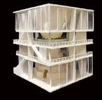
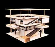
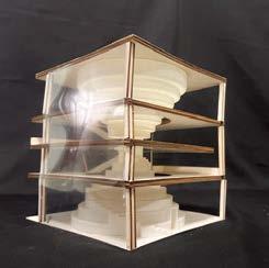
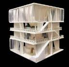
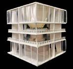
Following the design philosophy of have an extremely porous facade, glass walls were implemented at the more public top and bottom areas to allow vision to the funnel from the outside. Vertical louvres were used at the secondary external circulation to also emphasize a sort of verticality paired with the stairs in the overall design.
GROUP 1C MEMBERS
DIMENSIONS OF STRUCTURAL COMPONENTS (PRIMARY)
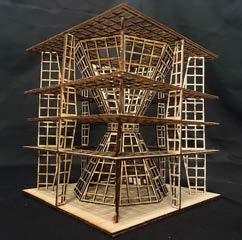
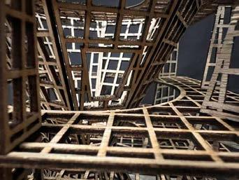
The funnel RC Walls have big enough holes serving as circulation pathways as well as apertures and openings for natural sunlight. The structural reasoning for this is also to achieve a lower center of gravity by having more mass on the lower portion of the RC wall, achieving greater structural stability. The openings occur at every other wall to achieve a well-balanced arrangement. The openings are made sure of to not to be too large as it could be interpreted as a RC Rigid Frame structure which would then be a flaw in our RC Wall strucutral frame system. These openings then serve to circulate to the other floors from and to the funnel.
(SECONDARY)
Lastly, we chose the RC Wall Frame structure for our final model proposal as the structure system allows for a more design-intuitive final space model than the steel structure model. Though admittedly that could be a feature in itself. However, the RC Wall structural system has a more porous and directed view towards the funnel which is more emphasized as a functional folly.
SCALE/PRECEDENT/CONTEXT
Driver - Vehicle - Destination
Ideas in the architecture to be investigated
Uses selected 'language' to analyze the idea EXERCISE 01 YEAR1 SEM 2
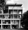
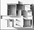
ARCHITECTURE: SHODAN HOUSE
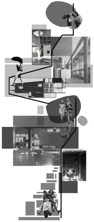
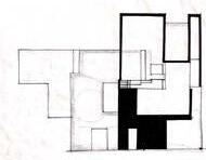
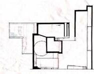
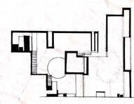
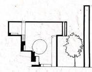
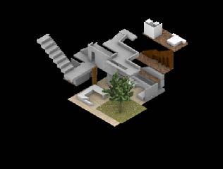
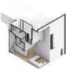
A Sensory Journey in Shodan House
Exploring Light and Wind, A Visual and Sensory Expedition Through Shodan House
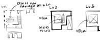
Stairs/Slopes Arrangement in Shodan House
Route for Inhabitants
Stairs/Slopes Arrangement in Shodan House
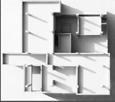
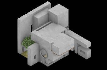
Isometric view of Shodan House
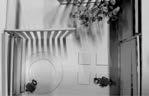
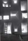
Spatial Classification Sunlight in each Level Sunlight in each Elevation
Light exploration in Spaces
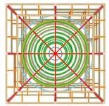
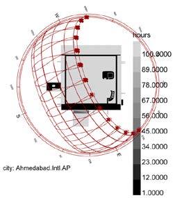
Direct Sunlight Hour in May in Shodan House
Accumulation of Direct Sunlight
Front View
Right View Left View
Back View
Isometric Section view
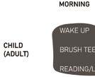
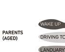
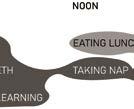
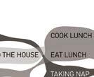
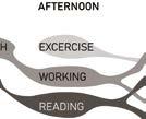
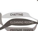
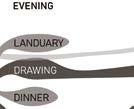
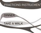
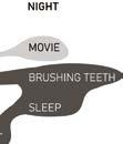
Activities throughout the Day
Area lighted up throughout the day
Sections of Light in different times
Different Arrangement of Walls
Design of the Wall based on the fluid Shadow
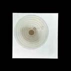
Reference of visualizing Wind
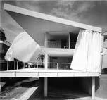
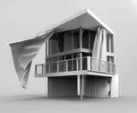
Curtain Wall House - Shigeru Ban
Location: Itabashi City, Tokyo 1730015, Japan
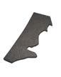
Shadow of fluid Material
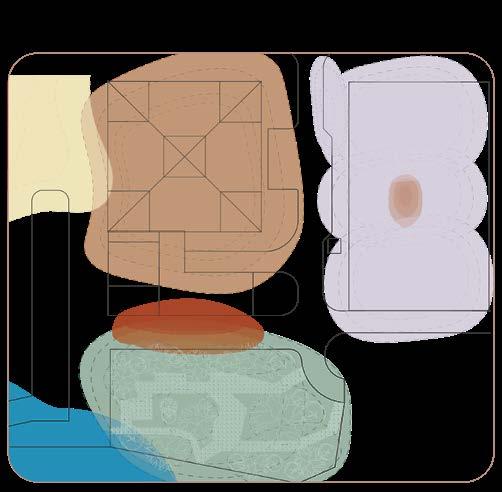
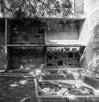
Found Archaeology on the Site
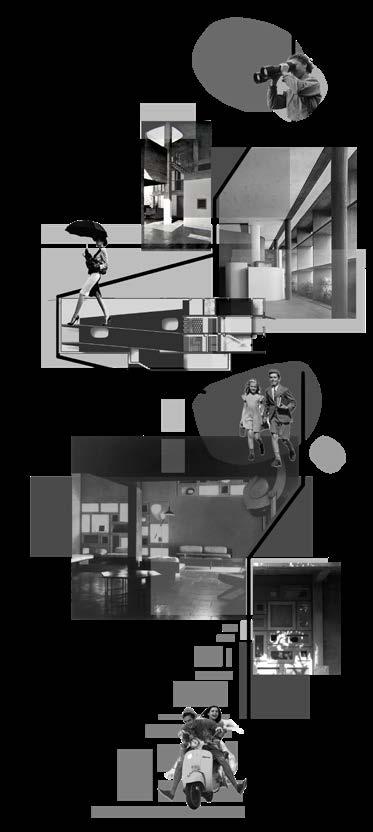
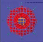
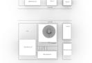
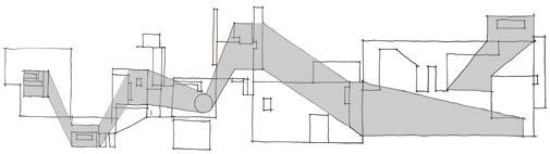
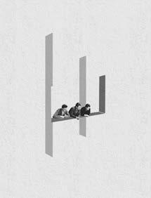
By analyzing the architectural elements in different perspectives, the collage is formed. All of the elements is connected by the shaded areas to show its positions.
Observing Element Being part of Element Interacting with Element
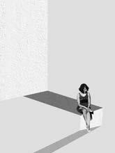
Body and Perception
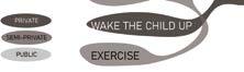
Private Chambers
Mapping the Interior
Color and Surfaces
Furniture and Objects
Clothing and Identity
Public Performance
Bridging the Interior and Exterior
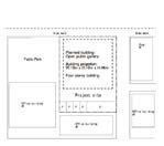
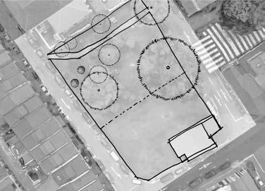
Site
- Ground level access
- Open green field - 2 car lot allowed to be removed
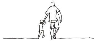
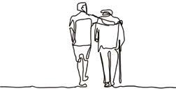
Evolving Relationship
Characteristics of Relationship Shift: - Dependency
- Conversion of Space used - Careness for Each Other
Spatial Relationship
Connection between Archeology and Occupants Iteration Models with Growing Age