WWW.DESIGNWORLDONLINE.COM
No GPS?
APRIL 2026
A E R O S PA C E & D E F E N S E T I P S :
No Problem
ALSO INSIDE
MCLAREN F1 TEAM TAPS GREENE TWEED FOR SEAL APPLICATION PAGE 16
ELECTRIC ACTUATION IN MACHINE TOOLS AND BEYOND: PRESSES PAGE 28
PAGE 53
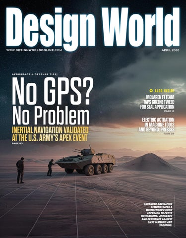
ADVANCED NAVIGATION DEMONSTRATED A MULTISENSOR FUSION APPROACH TO PROVE NAVIGATIONAL ACCURACY AND RESILIENCE AGAINST GNSS JAMMING AND SPOOFING.
Final Cover DW 04-26.indd 1
4/1/26 3:30 PM